| (7 intermediate revisions by 2 users not shown) | |||
| Line 1: | Line 1: | ||
| − | |||
| − | |||
| − | |||
| − | |||
| − | |||
| − | |||
| − | |||
| − | |||
| − | |||
| − | |||
| − | |||
| − | |||
| − | |||
| − | |||
| − | |||
| − | |||
| − | |||
| − | |||
| − | |||
| − | |||
| − | |||
| − | |||
| − | |||
| − | |||
| − | |||
| − | |||
| − | |||
| − | |||
| − | |||
| − | |||
| − | |||
| − | |||
| − | |||
| − | |||
'''Abstract.''' In this work, ductility limits of metallic materials, associated with the occurrence of strain localization, are predicted using the GTN damage model coupled with bifurcation theory. The resulting approach is implemented into the finite element code ABAQUS within the framework of large plastic strains and a fully three-dimensional formulation. A parametric study with respect to damage and hardening parameters is conducted in order to identify the most influential material parameters on strain localization. The analysis shows that the damage parameters have a significant impact on the predicted ductility limits, while the effect of hardening parameters on strain localization depends on the choice of void nucleation mechanism. | '''Abstract.''' In this work, ductility limits of metallic materials, associated with the occurrence of strain localization, are predicted using the GTN damage model coupled with bifurcation theory. The resulting approach is implemented into the finite element code ABAQUS within the framework of large plastic strains and a fully three-dimensional formulation. A parametric study with respect to damage and hardening parameters is conducted in order to identify the most influential material parameters on strain localization. The analysis shows that the damage parameters have a significant impact on the predicted ductility limits, while the effect of hardening parameters on strain localization depends on the choice of void nucleation mechanism. | ||
| Line 382: | Line 348: | ||
| [[Image:draft_ABED-MERAIM_291594830-image81-c.png|center|240px]] | | [[Image:draft_ABED-MERAIM_291594830-image81-c.png|center|240px]] | ||
| [[Image:draft_ABED-MERAIM_291594830-image82-c.png|center|240px]] | | [[Image:draft_ABED-MERAIM_291594830-image82-c.png|center|240px]] | ||
| + | |- | ||
| + | | <span style="text-align: center; font-size: 75%;">(a) </span> | ||
| + | | <span style="text-align: center; font-size: 75%;">(b)</span> | ||
|} | |} | ||
'''</div> | '''</div> | ||
| − | + | ||
<div class="center" style="width: auto; margin-left: auto; margin-right: auto;"> | <div class="center" style="width: auto; margin-left: auto; margin-right: auto;"> | ||
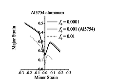
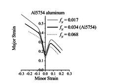
| − | <span style="text-align: center; font-size: 75%;">'''Figure 1''': Effect of the initial void volume fraction | + | <span style="text-align: center; font-size: 75%;">'''Figure 1''': Effect of the initial void volume fraction <math display="inline">f_0</math> (a), and the nucleation parameter <math display="inline">f_N</math> (b) on the ductility limit predictions for Al5754 aluminum</span></div> |
| − | <math display="inline">f_0</math> | + | |
| − | (a), and the nucleation parameter | + | |
| − | <math display="inline">f_N</math> | + | |
| − | (b) on the ductility limit predictions for Al5754 aluminum</span></div> | + | |
| − | Figure 1 shows the impact of varying one damage parameter at a time on the prediction of the ductility limits for Al5754 aluminum. Concerning the effect of the initial void volume fraction | + | Figure 1 shows the impact of varying one damage parameter at a time on the prediction of the ductility limits for Al5754 aluminum. Concerning the effect of the initial void volume fraction <math display="inline">f_0</math> (Figure 1(a)), large values for this parameter (e.g., <math display="inline">f_0=0.01</math>) imply that the material has already entered the coalescence stage, which dramatically lowers the predicted ductility limits. However, for very small values for parameter <math display="inline">f_0</math>, the ductility limit predictions are only slightly affected, which suggests that at such low void volume fraction levels, void growth is not the predominant mechanism for damage evolution. For the nucleation parameter <math display="inline">f_N</math>, the predicted ductility limits are lowered as this parameter increases. This trend is consistent with the physical meaning of this parameter (volume fraction of void-nucleating particles), as larger values for the latter tend to precipitate damage, thus promoting early plastic flow localization (see Eq. (6)). |
| − | <math display="inline">f_0</math> | + | |
| − | (Figure 1(a)), large values for this parameter (e.g., | + | |
| − | <math display="inline">f_0=0.01</math> | + | |
| − | ) imply that the material has already entered the coalescence stage, which dramatically lowers the predicted ductility limits. However, for very small values for parameter | + | |
| − | <math display="inline">f_0</math> | + | |
| − | , the ductility limit predictions are only slightly affected, which suggests that at such low void volume fraction levels, void growth is not the predominant mechanism for damage evolution. For the nucleation parameter | + | |
| − | <math display="inline">f_N</math> | + | |
| − | , the predicted ductility limits are lowered as this parameter increases. This trend is consistent with the physical meaning of this parameter (volume fraction of void-nucleating particles), as larger values for the latter tend to precipitate damage, thus promoting early plastic flow localization (see Eq. (6)). | + | |
==4.1.2 Effect of the hardening exponent <math display="inline">n</math>== | ==4.1.2 Effect of the hardening exponent <math display="inline">n</math>== | ||
| Line 424: | Line 381: | ||
<div class="center" style="width: auto; margin-left: auto; margin-right: auto;"> | <div class="center" style="width: auto; margin-left: auto; margin-right: auto;"> | ||
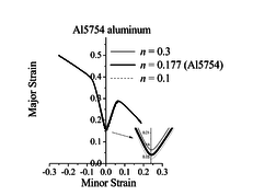
| − | <span style="text-align: center; font-size: 75%;">'''Figure 2''': Effect of the hardening exponent | + | <span style="text-align: center; font-size: 75%;">'''Figure 2''': Effect of the hardening exponent <math display="inline">n</math>, associated with the Swift law, on the ductility limit predictions for Al5754 aluminum with strain-controlled nucleation</span></div> |
| − | <math display="inline">n</math> | + | |
| − | , associated with the Swift law, on the ductility limit predictions for Al5754 aluminum with strain-controlled nucleation</span></div> | + | |
Similar trends have been observed in [9], where the GTN model was used with strain-controlled nucleation and coupled with the bifurcation theory. Indeed, in such a modeling approach, strain localization is mainly controlled by damage-induced softening, as shown in Figure 3(a) for the uniaxial tensile (UT) strain path, where it can be seen that flow localization occurs at strongly negative hardening moduli. Moreover, the evolution of void volume fraction based on strain-controlled nucleation for this particular loading path (UT) is shown to be insensitive to the strain hardening of the dense matrix material (see Figure 3(b)). | Similar trends have been observed in [9], where the GTN model was used with strain-controlled nucleation and coupled with the bifurcation theory. Indeed, in such a modeling approach, strain localization is mainly controlled by damage-induced softening, as shown in Figure 3(a) for the uniaxial tensile (UT) strain path, where it can be seen that flow localization occurs at strongly negative hardening moduli. Moreover, the evolution of void volume fraction based on strain-controlled nucleation for this particular loading path (UT) is shown to be insensitive to the strain hardening of the dense matrix material (see Figure 3(b)). | ||
| Line 436: | Line 391: | ||
| [[Image:draft_ABED-MERAIM_291594830-image91-c.png|center|234px]] | | [[Image:draft_ABED-MERAIM_291594830-image91-c.png|center|234px]] | ||
| [[Image:draft_ABED-MERAIM_291594830-image92-c.png|center|264px]] | | [[Image:draft_ABED-MERAIM_291594830-image92-c.png|center|264px]] | ||
| + | |- | ||
| + | | <span style="text-align: center; font-size: 75%;">(a)</span> | ||
| + | | <span style="text-align: center; font-size: 75%;">(b)</span> | ||
|} | |} | ||
</div> | </div> | ||
| − | + | ||
<div class="center" style="width: auto; margin-left: auto; margin-right: auto;"> | <div class="center" style="width: auto; margin-left: auto; margin-right: auto;"> | ||
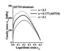
| − | <span style="text-align: center; font-size: 75%;">'''Figure 3''': Effect of the hardening exponent | + | <span style="text-align: center; font-size: 75%;">'''Figure 3''': Effect of the hardening exponent <math display="inline">n</math> on: (a) the Cauchy stressstrain curve, and (b) void volume fraction, until localization along the uniaxial tensile strain path</span></div> |
| − | <math display="inline">n</math> | + | |
| − | on: (a) the Cauchy stressstrain curve, and (b) void volume fraction, until localization along the uniaxial tensile strain path</span></div> | + | |
==4.2 Calibration of the GTN <math display="inline">q</math>-parameters== | ==4.2 Calibration of the GTN <math display="inline">q</math>-parameters== | ||
| Line 457: | Line 413: | ||
<div class="center" style="width: auto; margin-left: auto; margin-right: auto;"> | <div class="center" style="width: auto; margin-left: auto; margin-right: auto;"> | ||
| − | <span style="text-align: center; font-size: 75%;">'''Table 2''': Calibrated | + | <span style="text-align: center; font-size: 75%;">'''Table 2''': Calibrated <math display="inline">q</math>-parameters</span></div> |
| − | <math display="inline">q</math> | + | |
| − | -parameters</span></div> | + | |
{| style="margin: 1em auto 0.1em auto;border-collapse: collapse;" | {| style="margin: 1em auto 0.1em auto;border-collapse: collapse;" | ||
|- | |- | ||
| − | | style="border-top: 1pt solid black;border-left: 1pt solid black;border-bottom: 1pt solid black;text-align: center;"| | + | | style="border-top: 1pt solid black;border-left: 1pt solid black;border-bottom: 1pt solid black;text-align: center; width: 150px;"|<math display="inline">q</math>-parameter |
| − | <math display="inline">q</math> | + | | style="border-top: 1pt solid black;border-bottom: 1pt solid black;text-align: center; width: 150px;"|<math display="inline">n=0.025</math> |
| − | -parameter | + | |
| − | | style="border-top: 1pt solid black;border-bottom: 1pt solid black;text-align: center;"| | + | |
| − | <math display="inline">n=0.025</math> | + | |
| − | | style="border-top: 1pt solid black;border-bottom: 1pt solid black;text-align: center;"| | + | | style="border-top: 1pt solid black;border-bottom: 1pt solid black;text-align: center; width: 150px;"|<math display="inline">n=0.05</math> |
| − | <math display="inline">n=0.05</math> | + | |
| − | | style="border-top: 1pt solid black;border-bottom: 1pt solid black;border-right: 1pt solid black;text-align: center;"| | + | | style="border-top: 1pt solid black;border-bottom: 1pt solid black;border-right: 1pt solid black;text-align: center; width: 150px;"|<math display="inline">n=0.10</math> |
| − | <math display="inline">n=0.10</math> | + | |
|- | |- | ||
| − | | style="border-top: 1pt solid black;border-left: 1pt solid black;text-align: center;"| | + | | style="border-top: 1pt solid black;border-left: 1pt solid black;text-align: center; width: 150px;"|<math display="inline">q_1</math> |
| − | <math display="inline">q_1</math> | + | |
| − | | style="border-top: 1pt solid black;text-align: center;"|1.74 | + | | style="border-top: 1pt solid black;text-align: center; width: 150px;"|1.74 |
| − | | style="border-top: 1pt solid black;text-align: center;"|1.48 | + | | style="border-top: 1pt solid black;text-align: center; width: 150px;"|1.48 |
| − | | style="border-top: 1pt solid black;border-right: 1pt solid black;text-align: center;"|1.29 | + | | style="border-top: 1pt solid black;border-right: 1pt solid black;text-align: center; width: 150px;"|1.29 |
|- | |- | ||
| − | | style="border-left: 1pt solid black;border-bottom: 1pt solid black;text-align: center;"| | + | | style="border-left: 1pt solid black;border-bottom: 1pt solid black;text-align: center; width: 150px;"|<math display="inline">q_2</math> |
| − | <math display="inline">q_2</math> | + | |
| − | | style="border-bottom: 1pt solid black;text-align: center;"|1.013 | + | | style="border-bottom: 1pt solid black;text-align: center; width: 150px;"|1.013 |
| − | | style="border-bottom: 1pt solid black;text-align: center;"|1.013 | + | | style="border-bottom: 1pt solid black;text-align: center; width: 150px;"|1.013 |
| − | | style="border-bottom: 1pt solid black;border-right: 1pt solid black;text-align: center;"|0.982 | + | | style="border-bottom: 1pt solid black;border-right: 1pt solid black;text-align: center; width: 150px;"|0.982 |
|} | |} | ||
| Line 496: | Line 443: | ||
{| style="margin: 1em auto 0.1em auto;border-collapse: collapse;" | {| style="margin: 1em auto 0.1em auto;border-collapse: collapse;" | ||
|- | |- | ||
| − | | style="border-top: 1pt solid black;border-bottom: 1pt solid black;text-align: center;"|Material | + | | style="border-top: 1pt solid black;border-bottom: 1pt solid black;text-align: center; width: 150px;"|Material |
| − | | style="border-top: 1pt solid black;border-bottom: 1pt solid black;text-align: center;"| | + | | style="border-top: 1pt solid black;border-bottom: 1pt solid black;text-align: center; width: 150px;"|<math display="inline">f_0</math> |
| − | <math display="inline">f_0</math> | + | |
| − | | style="border-top: 1pt solid black;border-bottom: 1pt solid black;text-align: center;"| | + | | style="border-top: 1pt solid black;border-bottom: 1pt solid black;text-align: center; width: 150px;"|<math display="inline">s_N</math> |
| − | <math display="inline">s_N</math> | + | |
| − | | style="border-top: 1pt solid black;border-bottom: 1pt solid black;text-align: center;"| | + | | style="border-top: 1pt solid black;border-bottom: 1pt solid black;text-align: center; width: 150px;"|<math display="inline">{\epsilon }_N</math> |
| − | <math display="inline">{\epsilon }_N</math> | + | |
| − | | style="border-top: 1pt solid black;border-bottom: 1pt solid black;text-align: center;"| | + | | style="border-top: 1pt solid black;border-bottom: 1pt solid black;text-align: center; width: 150px;"|<math display="inline">f_N</math> |
| − | <math display="inline">f_N</math> | + | |
| − | | style="border-top: 1pt solid black;border-bottom: 1pt solid black;text-align: center;"| | + | | style="border-top: 1pt solid black;border-bottom: 1pt solid black;text-align: center; width: 150px;"|<math display="inline">f_{cr}</math> |
| − | <math display="inline">f_{cr}</math> | + | |
| − | | style="border-top: 1pt solid black;border-bottom: 1pt solid black;text-align: center;"| | + | | style="border-top: 1pt solid black;border-bottom: 1pt solid black;text-align: center; width: 150px;"|<math display="inline">{\delta }_{GTN}</math> |
| − | <math display="inline">{\delta }_{GTN}</math> | + | |
|- | |- | ||
| − | | style="border-top: 1pt solid black;border-bottom: 1pt solid black;text-align: center;"|Steel | + | | style="border-top: 1pt solid black;border-bottom: 1pt solid black;text-align: center; width: 150px;"|Steel |
| − | | style="border-top: 1pt solid black;border-bottom: 1pt solid black;text-align: center;"|0.001 | + | | style="border-top: 1pt solid black;border-bottom: 1pt solid black;text-align: center; width: 150px;"|0.001 |
| − | | style="border-top: 1pt solid black;border-bottom: 1pt solid black;text-align: center;"|0.1 | + | | style="border-top: 1pt solid black;border-bottom: 1pt solid black;text-align: center; width: 150px;"|0.1 |
| − | | style="border-top: 1pt solid black;border-bottom: 1pt solid black;text-align: center;"|0.3 | + | | style="border-top: 1pt solid black;border-bottom: 1pt solid black;text-align: center; width: 150px;"|0.3 |
| − | | style="border-top: 1pt solid black;border-bottom: 1pt solid black;text-align: center;"|0.05 | + | | style="border-top: 1pt solid black;border-bottom: 1pt solid black;text-align: center; width: 150px;"|0.05 |
| − | | style="border-top: 1pt solid black;border-bottom: 1pt solid black;text-align: center;"|0.04 | + | | style="border-top: 1pt solid black;border-bottom: 1pt solid black;text-align: center; width: 150px;"|0.04 |
| − | | style="border-top: 1pt solid black;border-bottom: 1pt solid black;text-align: center;"|5 | + | | style="border-top: 1pt solid black;border-bottom: 1pt solid black;text-align: center; width: 150px;"|5 |
|} | |} | ||
| Line 531: | Line 472: | ||
<div class="center" style="width: auto; margin-left: auto; margin-right: auto;"> | <div class="center" style="width: auto; margin-left: auto; margin-right: auto;"> | ||
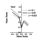
| − | <span style="text-align: center; font-size: 75%;">'''Figure 4''': Effect of the hardening exponent | + | <span style="text-align: center; font-size: 75%;">'''Figure 4''': Effect of the hardening exponent <math display="inline">n</math> on the prediction of ductility limits using the calibrated <math display="inline">q</math>-parameters</span></div> |
| − | <math display="inline">n</math> | + | |
| − | on the prediction of ductility limits using the calibrated | + | |
| − | <math display="inline">q</math> | + | |
| − | -parameters</span></div> | + | |
| − | <span id='_GoBack'></span>Figure 4 shows the effect of the hardening exponent | + | <span id='_GoBack'></span>Figure 4 shows the effect of the hardening exponent <math display="inline">n</math> of the power law on the prediction of ductility limits for the studied steel material based on the calibration of the <math display="inline">q</math>-parameters and strain-controlled nucleation model. The predicted ductility limits clearly show sensitivity to strain hardening for all strain paths, thanks to the use of micromechanics-based calibrated <math display="inline">q</math>-parameters. |
| − | <math display="inline">n</math> | + | |
| − | of the power law on the prediction of ductility limits for the studied steel material based on the calibration of the | + | |
| − | <math display="inline">q</math> | + | |
| − | -parameters and strain-controlled nucleation model. The predicted ductility limits clearly show sensitivity to strain hardening for all strain paths, thanks to the use of micromechanics-based calibrated | + | |
| − | <math display="inline">q</math> | + | |
| − | -parameters. | + | |
==4.3 Stress-controlled nucleation model== | ==4.3 Stress-controlled nucleation model== | ||
| Line 622: | Line 553: | ||
|} | |} | ||
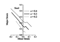
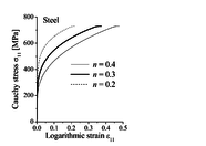
| − | Figure 5 illustrates the effect of the hardening exponent | + | Figure 5 illustrates the effect of the hardening exponent <math display="inline">n</math> on the prediction of limit strains for the studied steel material. It is clearly shown that the consideration of non-normality in the GTN model, due to stress-controlled nucleation, allows for a significant effect of strain hardening on the limit strains. Indeed, the predicted limit strains increase as the hardening exponent <math display="inline">n</math> increases, which is consistent with the literature findings (see, e.g., [11]). The effect of the hardening exponent <math display="inline">n</math> on the evolution of the Cauchy stress and the void volume fraction until localization for the UT strain path is shown in Figure 6. It can be seen that, in contrast to the case of strain-controlled nucleation (see Figure 3(b)), the evolution of void volume fraction is significantly affected by the hardening exponent <math display="inline">n</math>, which allows accounting for strain hardening effects on strain localization. Moreover, the Cauchy stress evolution reveals that the hardening modulus at localization is not strongly negative, as compared to that obtained in the case of strain-controlled nucleation. This is caused by the non-normality of the plastic flow, which plays a destabilizing role in the localization bifurcation analysis. |
| − | <math display="inline">n</math> | + | |
| − | on the prediction of limit strains for the studied steel material. It is clearly shown that the consideration of non-normality in the GTN model, due to stress-controlled nucleation, allows for a significant effect of strain hardening on the limit strains. Indeed, the predicted limit strains increase as the hardening exponent | + | |
| − | <math display="inline">n</math> | + | |
| − | increases, which is consistent with the literature findings (see, e.g., [11]). The effect of the hardening exponent | + | |
| − | <math display="inline">n</math> | + | |
| − | on the evolution of the Cauchy stress and the void volume fraction until localization for the UT strain path is shown in Figure 6. It can be seen that, in contrast to the case of strain-controlled nucleation (see Figure 3(b)), the evolution of void volume fraction is significantly affected by the hardening exponent | + | |
| − | <math display="inline">n</math> | + | |
| − | , which allows accounting for strain hardening effects on strain localization. Moreover, the Cauchy stress evolution reveals that the hardening modulus at localization is not strongly negative, as compared to that obtained in the case of strain-controlled nucleation. This is caused by the non-normality of the plastic flow, which plays a destabilizing role in the localization bifurcation analysis. | + | |
<div class="center" style="width: auto; margin-left: auto; margin-right: auto;"> | <div class="center" style="width: auto; margin-left: auto; margin-right: auto;"> | ||
| Line 638: | Line 561: | ||
<div class="center" style="width: auto; margin-left: auto; margin-right: auto;"> | <div class="center" style="width: auto; margin-left: auto; margin-right: auto;"> | ||
| − | <span style="text-align: center; font-size: 75%;">'''Figure 5''': Effect of the hardening exponent | + | <span style="text-align: center; font-size: 75%;">'''Figure 5''': Effect of the hardening exponent <math display="inline">n</math> on the prediction of ductility limits for the studied steel material with stress-controlled nucleation</span></div> |
| − | <math display="inline">n</math> | + | |
| − | on the prediction of ductility limits for the studied steel material with stress-controlled nucleation</span></div> | + | |
<div class="center" style="width: auto; margin-left: auto; margin-right: auto;"> | <div class="center" style="width: auto; margin-left: auto; margin-right: auto;"> | ||
| Line 648: | Line 569: | ||
| [[Image:draft_ABED-MERAIM_291594830-image110-c.png|center|186px]] | | [[Image:draft_ABED-MERAIM_291594830-image110-c.png|center|186px]] | ||
| [[Image:draft_ABED-MERAIM_291594830-image111-c.png|center|198px]] | | [[Image:draft_ABED-MERAIM_291594830-image111-c.png|center|198px]] | ||
| + | |- | ||
| + | | <span style="text-align: center; font-size: 75%;">(a)</span> | ||
| + | | <span style="text-align: center; font-size: 75%;">(b)</span> | ||
|} | |} | ||
'''</div> | '''</div> | ||
| − | + | ||
<div class="center" style="width: auto; margin-left: auto; margin-right: auto;"> | <div class="center" style="width: auto; margin-left: auto; margin-right: auto;"> | ||
| − | <span style="text-align: center; font-size: 75%;">'''Figure 6''': Effect of the hardening exponent | + | <span style="text-align: center; font-size: 75%;">'''Figure 6''': Effect of the hardening exponent <math display="inline">n</math> on: (a) the Cauchy stressstrain curve, and (b) void volume fraction, until localization along the UT strain path, in the case of stress-controlled nucleation</span></div> |
| − | <math display="inline">n</math> | + | |
| − | on: (a) the Cauchy stressstrain curve, and (b) void volume fraction, until localization along the UT strain path, in the case of stress-controlled nucleation</span></div> | + | |
| − | == | + | ==5 CONCLUSIONS== |
| − | In this work, The GTN ductile damage model has been coupled with bifurcation theory to predict the occurrence of strain localization for metallic materials. The resulting approach has been implemented into the finite element software ABAQUS/standard in the framework of large plastic strains and a fully three-dimensional formulation. Ductility limits of metallic materials are then predicted using the proposed approach. A parametric study with respect to damage and hardening parameters has been conducted in order to determine the most influential parameters on strain localization. The analysis showed that the damage parameters have a significant impact on the predicted ductility limits. With regard to hardening, it is shown that the choice of void nucleation mechanism has an important influence on the sensitivity of the predicted ductility limits to strain hardening. Indeed, in the case of strain-controlled nucleation, the predicted limit strains were found almost insensitive to strain hardening for most strain paths, while a significant influence was observed in the case of stress-controlled nucleation. The latter leads to non-normality in the plastic flow rule, which plays a destabilizing role that promotes early strain localization. This work also discussed the use of a micromechanics-based calibration for the GTN | + | In this work, The GTN ductile damage model has been coupled with bifurcation theory to predict the occurrence of strain localization for metallic materials. The resulting approach has been implemented into the finite element software ABAQUS/standard in the framework of large plastic strains and a fully three-dimensional formulation. Ductility limits of metallic materials are then predicted using the proposed approach. A parametric study with respect to damage and hardening parameters has been conducted in order to determine the most influential parameters on strain localization. The analysis showed that the damage parameters have a significant impact on the predicted ductility limits. With regard to hardening, it is shown that the choice of void nucleation mechanism has an important influence on the sensitivity of the predicted ductility limits to strain hardening. Indeed, in the case of strain-controlled nucleation, the predicted limit strains were found almost insensitive to strain hardening for most strain paths, while a significant influence was observed in the case of stress-controlled nucleation. The latter leads to non-normality in the plastic flow rule, which plays a destabilizing role that promotes early strain localization. This work also discussed the use of a micromechanics-based calibration for the GTN <math display="inline">q</math>-parameters in the case of strain-controlled nucleation, which is shown to allow accounting for hardening effects on strain localization predictions. |
| − | <math display="inline">q</math> | + | |
| − | -parameters in the case of strain-controlled nucleation, which is shown to allow accounting for hardening effects on strain localization predictions. | + | |
==REFERENCES== | ==REFERENCES== | ||
Latest revision as of 17:27, 27 April 2017
Abstract. In this work, ductility limits of metallic materials, associated with the occurrence of strain localization, are predicted using the GTN damage model coupled with bifurcation theory. The resulting approach is implemented into the finite element code ABAQUS within the framework of large plastic strains and a fully three-dimensional formulation. A parametric study with respect to damage and hardening parameters is conducted in order to identify the most influential material parameters on strain localization. The analysis shows that the damage parameters have a significant impact on the predicted ductility limits, while the effect of hardening parameters on strain localization depends on the choice of void nucleation mechanism.
1 INTRODUCTION
It is well known that in sheet metal forming processes, different types of defects may occur, which are usually associated with operating conditions and/or material characteristics. Plastic instabilities, corresponding to the occurrence of zones of highly localized plastic strain, are examples of these undesirable phenomena. To characterize the formability of thin sheet metals, the concept of forming limit diagram has been introduced [1]. Among the most influential constitutive features on the formability limits of thin sheet metals, the damage development is of particular importance. In this context, Gurson-type damage models have been developed, among which the GTN model [2], which is adopted in this work to describe the initiation of ductile damage and its evolution during loading. This model is coupled with the bifurcation analysis [3,4] to predict the occurrence of strain localization in metallic materials. The present work investigates the respective effect of damage and hardening parameters on the prediction of ductility limits using different void nucleation mechanisms. In addition, an alternative modeling approach is explored for the analysis of hardening effects on strain localization, which consists in adopting a micromechanics-based calibration for the GTN -parameters.
2 GTN DAMAGE MODEL
The ductile damage model adopted in this work is based on the Gurson model, which accounts for void nucleation and growth. This model has been subsequently modified in the literature leading to the following well-known GTN yield potential (see, e.g., [2]):
|
, |
(1) |
where , and are material parameters; is the hydrostatic stress defined by , with being the Cauchy stress tensor and the second-order identity tensor; is the von Mises equivalent stress defined by , with being the deviatoric part of the Cauchy stress; is the flow stress, function of the equivalent plastic strain of the fully dense matrix; is the modified void volume fraction, function of the actual void volume fraction , which is defined by
|
with |
(2) |
where the damage parameters and are the critical void volume fraction, at which the coalescence stage starts, and the void volume fraction at final fracture, respectively. According to Eq. (2), reaches its ultimate value when .
The tensile flow stress of the fully dense matrix material is assumed to be governed by an isotropic hardening law, as given by the following rate expression:
|
, |
(3) |
where is the plastic hardening modulus of the fully dense matrix material. The plastic flow rule follows the classical normality law, which defines the plastic strain rate as
|
, |
(4) |
where is the plastic multiplier, and is the direction of the plastic flow. The evolution of void volume fraction depends on both growth of pre-existent voids and nucleation of new ones. For the nucleation of new voids, the model proposed by Chu and Needleman [5] is adopted in this work. This model involves the contribution of both the flow stress rate of the dense matrix and the hydrostatic stress rate. The final expression of the incremental change in void volume fraction is given by
|
. |
(5) |
In the above equation, the constants and allow characterizing the void nucleation model, which is strain controlled for and , and stress controlled for and . Their expressions follow normal distribution laws as proposed in [5]
|
, |
(6) |
where and are the mean strain and the mean stress for nucleation, respectively; is the standard deviation on
is the volume fraction of void-nucleating particles; is the initial yield stress of the matrix surrounding the voids. In the co-rotational frame, which is associated with the Jaumann objective derivative, the Cauchy stress rate is expressed using the following hypoelastic law:
|
, |
(7) |
where is the strain rate tensor, is the fourth-order elasticity tensor, and is the elastic–plastic tangent modulus. Using the consistency condition , together with the above equations, the plastic multiplier writes
|
, |
(8) |
where
|
, |
(9) |
|
|
(10) |
By replacing the plastic multiplier (see Eq. (8)) into the hypoelastic law (Eq. (7)), the elasticplastic tangent modulus of the GTN model writes
|
. |
(11) |
It can be observed that, in the case of strain-controlled nucleation (i.e., and ), the above elasticplastic tangent modulus becomes symmetric and the normality of the plastic flow rule holds. In the case of stress-controlled nucleation (i.e., and ), the elasticplastic tangent modulus is non-symmetric and the normality of the plastic flow rule does not hold.
3 BIFURCATION CRITERION
In this section, the constitutive equations described above are coupled with a plastic instability criterion, as proposed by Rudnicki and Rice [3] and Rice [4], in order to predict the occurrence of strain localization. This criterion is based on bifurcation theory, where the incipience of plastic flow localization in the form of an infinite band is associated with the loss of uniqueness for the solution of the rate equilibrium equations. According to this criterion, the critical condition, which also corresponds to the loss of ellipticity of the associated boundary value problem, is related to the singularity of the acoustic tensor , defined as , where is the normal to the localization band and the tangent modulus writes
|
, |
(12) |
where , and are fourth-order tensors that consist of Cauchy stress components. These additional tensors originate from the large-strain framework and their complete expressions can be found in [6,7]. The critical condition is then given by
|
. |
(13) |
4 PREDICTION OF DUCTILITY LIMITS
In this section, the GTN model is coupled with the bifurcation analysis to predict strain localization in porous materials subjected to in-plane loading conditions. The resulting approach is implemented into the finite element code ABAQUS/Standard within the framework of large plastic strains and a fully three-dimensional formulation. The effect of hardening and damage parameters, as well as the choice of nucleation modeling, on the prediction of ductility limits is analyzed.
4.1 Strain-controlled nucleation model
In this section, nucleation of new voids is taken strain-controlled, by considering and in the GTN model (see Eq. (5)). It is worth noting that, in this case, the normality of the plastic flow rule holds and the elastic–plastic tangent modulus is symmetric, while the acoustic tensor is non-symmetric due to the convective stress components (Eq. (12)).
The material considered here is Al5754 aluminum, with Young’s modulus and Poisson’s ratio equal to MPa and 0.33, respectively. The associated hardening parameters, according to the Swift isotropic hardening law, and damage parameters are summarized in Table 1 (see [8]).
|
|
|
|
|
|
|
|
|
|
|
|
| |||
| 0.00173 | 309.1 | 0.177 | 0.001 | 0.1 | 0.32 | 0.034 | 0.00284 | 7 | 1.5 | 1.0 | 2.15 |
4.1.1 Effect of damage parameters
The effect of damage parameters on the ductility limit predictions for the Al5754 aluminum alloy is analyzed here. A relatively large number of damage parameters are involved in the GTN model; for conciseness, attention is focused on the initial void volume fraction and the nucleation parameter .
Figure 1 shows the impact of varying one damage parameter at a time on the prediction of the ductility limits for Al5754 aluminum. Concerning the effect of the initial void volume fraction (Figure 1(a)), large values for this parameter (e.g., ) imply that the material has already entered the coalescence stage, which dramatically lowers the predicted ductility limits. However, for very small values for parameter , the ductility limit predictions are only slightly affected, which suggests that at such low void volume fraction levels, void growth is not the predominant mechanism for damage evolution. For the nucleation parameter , the predicted ductility limits are lowered as this parameter increases. This trend is consistent with the physical meaning of this parameter (volume fraction of void-nucleating particles), as larger values for the latter tend to precipitate damage, thus promoting early plastic flow localization (see Eq. (6)).
4.1.2 Effect of the hardening exponent 4.1.2 Effect of the hardening exponent
n
{\textstyle n}
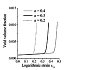
The impact of the hardening exponent , associated with the Swift law, on the ductility limit predictions is analyzed here for the Al5754 aluminum material. Figure 2 shows the predicted limit strains obtained with different hardening exponents for the dense matrix material. These results reveal that the effect of the hardening exponent on the ductility limit predictions is much smaller than that observed for damage parameters (see the previous section). Similar results are observed when varying the and Swift hardening parameters, and are not reported here for conciseness. However, a more perceptible effect is found near the plane-strain tension (PST) loading path (see Figure 2).
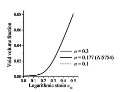
Similar trends have been observed in [9], where the GTN model was used with strain-controlled nucleation and coupled with the bifurcation theory. Indeed, in such a modeling approach, strain localization is mainly controlled by damage-induced softening, as shown in Figure 3(a) for the uniaxial tensile (UT) strain path, where it can be seen that flow localization occurs at strongly negative hardening moduli. Moreover, the evolution of void volume fraction based on strain-controlled nucleation for this particular loading path (UT) is shown to be insensitive to the strain hardening of the dense matrix material (see Figure 3(b)).
4.2 Calibration of the GTN -parameters4.2 Calibration of the GTN
q
{\textstyle q}
-parameters
The previous results have shown limitations of the GTN model, with strain-controlled nucleation, in accounting for the effect of strain hardening on the porosity evolution. To overcome such limitations, Faleskog et al. [10] suggested calibrating the GTN -parameters in order to include the effect of strain hardening on void growth. Tables 2 and 3 summarize the calibrated -parameters and the damage parameters for a steel material with yield strength ratio (see [10]). The isotropic hardening model used in the simulations is based on a hardening power law (see [10]).
| -parameter | |||
| 1.74 | 1.48 | 1.29 | |
| 1.013 | 1.013 | 0.982 |
| Material | ||||||
| Steel | 0.001 | 0.1 | 0.3 | 0.05 | 0.04 | 5 |
Figure 4 shows the effect of the hardening exponent of the power law on the prediction of ductility limits for the studied steel material based on the calibration of the -parameters and strain-controlled nucleation model. The predicted ductility limits clearly show sensitivity to strain hardening for all strain paths, thanks to the use of micromechanics-based calibrated -parameters.
4.3 Stress-controlled nucleation model
The effect of strain hardening on the ductility limits is investigated in this section using the GTN model with stress-controlled nucleation. The associated material parameters corresponding to a steel material are summarized in Table 4. The Ludwig power law is used in the simulations for the modeling of isotropic hardening for the dense matrix material.
|
|
|
|
|
|
|
|
|
|
| |||||||||
| 150 | 800 | 0.001 | 0.1 | 1000 | 0.05 | 0.04 | 10 | 1.5 | 1.0 | 2.15 |
Figure 5 illustrates the effect of the hardening exponent on the prediction of limit strains for the studied steel material. It is clearly shown that the consideration of non-normality in the GTN model, due to stress-controlled nucleation, allows for a significant effect of strain hardening on the limit strains. Indeed, the predicted limit strains increase as the hardening exponent increases, which is consistent with the literature findings (see, e.g., [11]). The effect of the hardening exponent on the evolution of the Cauchy stress and the void volume fraction until localization for the UT strain path is shown in Figure 6. It can be seen that, in contrast to the case of strain-controlled nucleation (see Figure 3(b)), the evolution of void volume fraction is significantly affected by the hardening exponent , which allows accounting for strain hardening effects on strain localization. Moreover, the Cauchy stress evolution reveals that the hardening modulus at localization is not strongly negative, as compared to that obtained in the case of strain-controlled nucleation. This is caused by the non-normality of the plastic flow, which plays a destabilizing role in the localization bifurcation analysis.
5 CONCLUSIONS
In this work, The GTN ductile damage model has been coupled with bifurcation theory to predict the occurrence of strain localization for metallic materials. The resulting approach has been implemented into the finite element software ABAQUS/standard in the framework of large plastic strains and a fully three-dimensional formulation. Ductility limits of metallic materials are then predicted using the proposed approach. A parametric study with respect to damage and hardening parameters has been conducted in order to determine the most influential parameters on strain localization. The analysis showed that the damage parameters have a significant impact on the predicted ductility limits. With regard to hardening, it is shown that the choice of void nucleation mechanism has an important influence on the sensitivity of the predicted ductility limits to strain hardening. Indeed, in the case of strain-controlled nucleation, the predicted limit strains were found almost insensitive to strain hardening for most strain paths, while a significant influence was observed in the case of stress-controlled nucleation. The latter leads to non-normality in the plastic flow rule, which plays a destabilizing role that promotes early strain localization. This work also discussed the use of a micromechanics-based calibration for the GTN -parameters in the case of strain-controlled nucleation, which is shown to allow accounting for hardening effects on strain localization predictions.
REFERENCES
[1] Keeler, S. and Backofen, W.A. Plastic instability and fracture in sheets stretched over rigid punches. ASM Trans. Quart. (1963) 56:25-48.
[2] Tvergaard, V. and Needleman, A. Analysis of the cup-cone fracture in a round tensile bar. Acta Metallurgica (1984) 32:157-169.
[3] Rudnicki, J.W. and Rice, J.R. Conditions for the localization of deformation in pressure sensitive dilatant materials. Journal of the Mechanics and Physics of Solids (1975) 23:371-394.
[4] Rice, J.R. The localization of plastic deformation. Theorical and Applied Mechanics. Koiter ed., 207-227, (1976).
[5] Chu, C. and Needleman, A. Void nucleation effects in biaxially stretched sheets. Journal of Engineering Materials and Technology (1980) 102:249-256.
[6] Abed-Meraim, F., Balan, T. and Altmeyer, G. Investigation and comparative analysis of plastic instability criteria: application to forming limit diagrams. International Journal of Advanced Manufacturing Technology (2014) 71:1247-1262.
[7] Ben Bettaieb, M. and Abed-Meraim, F. Investigation of localized necking in substrate-supported metal layers: Comparison of bifurcation and imperfection analyses. International Journal of Plasticity (2015) 65:168-190.
[8] Brunet, M., Mguil, S. and Morestin, F. Analytical and experimental studies of necking in sheet metal forming processes. Journal of Materials Processing Technology (1998) 80-81:40-46.
[9] Mansouri, L.Z., Chalal, H. and Abed-Meraim, F. Ductility limit prediction using a GTN damage model coupled with localization bifurcation analysis. Mechanics of Materials (2014) 76:64-92.
[10] Faleskog, J., Gao, X. and Shih, C.F. Cell model for nonlinear fracture analysis – I. Micromechanics calibration. International Journal of Fracture (1998) 89:355-373.
[11] Doghri, I. and Billardon, R. Investigation of localization due to damage in elasto-plastic materials. Mechanics of Materials (1995) 19:129-149.
Document information
Published on 27/04/17
Submitted on 27/04/17
Licence: Other
Share this document
Keywords
claim authorship
Are you one of the authors of this document?
