Abstract
The energy optimal motion planning of a hopping robot with three links is investigated in the flight phase. Firstly, the conservation equation of angular momentum of the hopping robot in the flight phase is established which is a nonholonomic constraint. Then the energy consumption of the robot in the flight phase is selected as the optimization goal. Given the initial and terminal positions, the Gaussian pseudospectrum method is used to solve the optimal control problem. The simulation results show that the initial angular momentum has a great influence on the performance of the hopping robot. With the zero initial angular momentum, although the flight time can be selected arbitrarily, the greater the flight time, the smaller the energy consumption, the force required by the robot is greater. Thus, it is necessary to select an appropriate value.
Keywords: Hopping robot, flight phase, nonholonomic constraint, optimal motion planning
1. Introduction
Compared with wheeled or tracked robots, hopping robots move in a jumping manner and are capable of crossing obstacles which are several times their own size. They use discrete landing points to make contact with the ground and have strong adaptability to complex and unstructured terrain. The study of hopping robots has become a research focus in recent years [1]. Among them, Professor Raibert’s team has made groundbreaking research in the field of hopping robots, and their designed model of a single legged telescopic hopping robot provides a reference for subsequent research [2-6].
Before controlling the robot, it is necessary to plan the motion trajectory of the hopping robot [7-11]. Vermeulen [7] planned the robot based on its target motion parameters and used a quintic polynomial to describe the robot’s trajectory. Wu et al. [9]studied hopping robots with flat feet, using Bezier curves to represent the trajectory of active joints, and planning the trajectory based on minimizing driving energy.
In the flight phase, the robot foot is released from the ground. At this time, the only external force on the robot is gravity. The robot meets the principle of conservation of angular momentum, and is a nonholonomic constraint system. Due to the non integrability of nonholonomic constraints, its motion planning problem is much more complex than that of general systems. Rehman et al. [12] used a time-varying feedback control strategy to plan the motion during the flight phase. Guo et al. [13] used the direct single shot method to plan the jumping gait of a robot with four links, and its flight phase was almost passive.
The most commonly used motion planning methods for nonholonomic system can be divided into two categories, namely, the direct method and the indirect method [14-16]. The indirect method is based on the maximum (minimum) value principle, which transforms the optimal motion planning problem into a two-point boundary value problem. Its advantage is that the local optimal solution can be found, but it is difficult to guess the initial solution, and the radius of convergence is small. The direct method uses the parametric method to transform the optimal motion planning problem of the continuous system into a nonholonomic motion planning problem, and then obtains the optimal motion trajectory by solving the non motion planning problem. This method does not need to solve the first order optimal condition, and the radius of convergence is large. Pseudospectral method is the most widely used method among them.
In this paper, the optimal motion planning of a hopping robot with three links in the flight phase is studied. First, the constraint equation of the hopping robot in the flight phase is established according to the conservation principle of angular momentum. Then, the energy optimal motion planning problem is transformed into a nonholonomic motion planning problem by using the Gaussian pseudospectral method, and the problem is solved. The simulation results demonstrate the effectiveness of this method. Because the initial angular momentum has a great impact on the hopping robot. This paper finally analyzes the impact of the initial angular momentum on the hopping performance of the robot.
2. Dynamic model
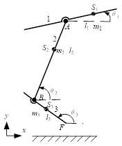
The kinematics model of the robot in the flight phase is shown in Figure 1. The hopping robot consists of three components: body represented by 1, legs denoted by 2, and feet, namely, 3. In order to simplify the analysis, it is assumed that the motion of the hopping robot is limited to the sagittal plane, without considering the lateral motion. Assuming the length of each member of the robot is , the mass is mi, the position of the centroid Si of the body is , and ( is the proportion factor of each centroid position), and . The rotational inertia of each member around the center of mass is .
Based on a floating coordinate with hip joint position A as the origin, the dynamic model is established. The generalized coordinate of the robot is , where is the absolute coordinate of the body, is the relative angle between the body and legs (counterclockwise is positive), namely, , is the relative angle between the legs and feet, i.e. .
|
| Figure 1. Model of robot during flight phase |
During the flight phase, the influence of air drag and internal friction of the robot on the robot’s hopping motion is ignored, and the robot’s total center of mass moves in a parabolic motion with the gravity. If the flight time is , then the horizontal and vertical motion of the center of mass can be written as
|
|
(1) |
where, and are the horizontal and vertical positions of the robot’s total center of mass at the flight time, respectively. and are the horizontal and vertical velocities of the total center of mass at the flight time, respectively. The position of the robot at the touchdown is completely determined by the flight conditions.
The rotation of the robot can be expressed by the angular momentum of the robot with regarding to the total center of mass. Angular momentum can be calculated as follows:
|
|
(2) |
where, , , is the position of the centroid of each component, and is the position of the total centroid.
The only external force on the robot in the flight phase is gravity. So the robot meets the principle of conservation of angular momentum about the total center of mass. Supposing that the angular momentum of the robot at the initial moment of the flight phase is , one can obtain:
|
|
(3) |
where is a function of joint rotation angle. The equation above indicates that the system is a nonholonomic system with Pfaffian constraints, and it has a cyclic coordinate .
During the flight phase, the robot is only equipped with actuators in the hip and ankle joints. So the joint angular velocity and are selected as the control inputs for the system. Eq.(3) can be written in state space form. When do not equal 0, it is an affine nonlinear system with three states and two inputs and drift terms
|
|
(4) |
where, .
When the initial angular momentum of the system is not zero, , then the system has no balance point.
The optimal trajectory planning of a robot refers to the initial position and terminal position of the given robot, by searching for a set of control inputs to enable the robot to move along a path that satisfies incomplete constraints. Meanwhile, the robot can move from the initial position to the terminal position within a given time , and achieve an extreme performance index.
In robot systems, due to the limited energy that robots can carry, in order to make the robot move for a longer time, it is necessary to consider the energy consumption of the robot. According to the minimum energy consumption theorem, in this paper the energy consumed by the hopping robot during flight phase is selected as the optimal control objective. Due to the fact that the usual driving method for robots is motor, and the energy consumed by the motor is proportional to its velocity, the performance index function can be expressed as follows:
|
|
(5) |
In the flight phase, the optimal planning problem of a hopping robot can be described as: finding suitable control input variables to achieve the minimum performance index, i.e. Eq.(5). Meanwhile, the state variable and initial time and flight time satisfy the following constraints:
|
|
(6) |
where and T are constant.
3. Pseudospectral method for solving optimal control problems
In recent years, the pseudospectral method has become one of the important methods for solving optimal control problems [12]. The basic principle of the pseudospectral method is to discretize the continuous optimal control problem at the orthogonal collocation points, and approximate the state and control variables through the global interpolation polynomial. Thus the optimal control problem can be transformed into a nonlinear programming problem (NLP).
According to the different orthogonal collocation points, there are four widely used pseudospectral methods: Gaussian pseudospectral method, Radau pseudospectral method, Legendre pseudospectral method and Chebyshev pseudospectral method. Legendre pseudospectral method has the advantages of convergence speed of exponential function, insensitivity to initial value guess, and large radius of convergence. So Legendre pseudospectral method is adopted in this paper.
The Legendre pseudospectral method uses the roots of orthogonal polynomials as collocation points and global orthogonal polynomials as finite bases. The system’s state and control variables are discretized at the Lendre Guass Lobatto (LGL) point. The Lagrange interpolation polynomial is used to approximate the state and control variables, obtaining the discrete dynamic equations at the points. Thus, the differential operation in the state equation and the integral operation in the performance index function are transformed into algebraic operation, and finally the optimal control problem is transformed into a nonlinear programming problem with the state variables and control variables at the points as the parameters to be optimized.
Dynamic equation:
|
|
(7) |
Boundary condition:
|
|
(8) |
Inequality path constraint
|
|
(9) |
where is the performance indicator, is the Mayer type performance indicator, is the Lagrange type performance indicator, and is the state equation function vector, is the initial and terminal constraint function vector, and is the equation and inequality path constraint function vector.
The calculation process of Legendre pseudospectral method is as follows: first, the value range of the original planning problem is mapped from to the distribution interval of discrete points in the pseudospectral method through time domain transformation .
The Legendre orthogonal polynomial on the interval is
|
|
(10) |
where represents n-order Legendre polynomials.
In order to achieve better interpolation approximation, , and zeros of the first derivative of the Legendre polynomial is defined as an LGL point, there are control points, denoted as .
Using LGL points as interpolation points, n-order Lagrangian interpolation polynomials is constructed to approximate the continuous state variable and control variable , and obtain the following equations:
|
|
(11) |
|
|
(12) |
where, is the -order Lagrangian interpolation basis function,
|
|
(13) |
where, , satisfies the relationship , if , there is ; if , .
After parameterizing the state variable through interpolation polynomials, the differential operation of the state equation can be approximated as the differential operation of the interpolation basis function, and the derivative of the state variable can be approximated as follows:
|
|
(14) |
where , is the differential matrix, representing the differential value of Lagrange basis function at each LGL control point, is the th element. One can obtain
|
|
(15) |
Now, the constraints of the state equation can be transformed into discrete state equations at N+1 LGL control points.
|
|
(16) |
The boundary and path constraints after discretization can be described as follows:
|
|
(17) |
|
|
(18) |
where .
Through Gauss-Lobatto numerical integration, the integral term in the performance index function is transformed into the following algebraic expression:
|
(19) |
where, is Gauss weights, defining
|
|
(20) |
Through the above discretization and approximation processing, the optimal control problem can be further described by Eqs.(7)-(9) as follows: solving the values of the state variable at interpolation points and the control variable at interpolation points , so that the performance index function takes the minimum value and satisfies the constraint conditions of Eqs. (16)-(18).
For the energy optimal path planning problem of the hopping robot in this paper, given the initial position and terminal position of the system, two sets of unknown coefficients and are solved, resulting in a minimal discrete performance index function
|
|
(21) |
Further, the following discrete system dynamic equation constraints can be satisfied:
|
|
(22a) | |
|
|
(22b) | |
|
|
(22c) |
where , , and are elements in the state equation of the hopping robot system.
In actual robot control, there are limitations on motor torque and speed, so there are upper and lower limits on the actual control input of the system, which can be expressed as discrete inequality constraints as shown in the following equation:
|
|
(23) |
where , , is the upper limit of the control input.
4. Results
The physical parameters of the robot based on the hopping pattern of the kangaroo is determined as shown in Table 1.
| Component number | 1 | 2 | 3 |
|---|---|---|---|
| Length of rod | 0.11 | 0.26 | 0.174 |
| Centroid moment separation | 0.11 | 0.105 | 0.082 |
| Mass of rod | 4.24 | 0.06 | 0.14 |
| Moment of inertia | 0.034 | 0.0033 | 0.0038 |
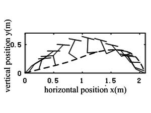
The initial and terminal positions of the given motion planning of the hopping robot system are and , respectively. The flight time , , and the control constraints are , . The simulation results are shown in Figures 2-4. It can be seen that the hopping robot can complete the motion planning requirements and reach the preset goal position within the given time.
|
| Figure 2. Posture diagram during flight phase |
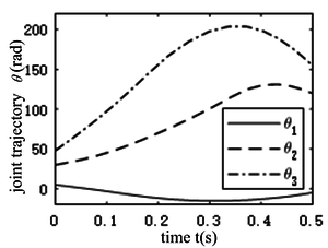
From Figure 3 it can be seen that the joint trajectory of the foot shows a trend of first rising and then falling, which means that the foot lifts inward and then quickly swings downwards during most of the flight phase, preparing to touch the ground. The range of changes in the ankle joint is the largest among the three curves, approximately from 48 ° to 205°. The range of body swing is relatively small, ranging from -16° to 5°, and the changes are relatively gentle.
|
| Figure 3. Joint angles of the hopping robot |
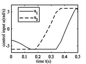
Figure 4 is the control input for the hopping robot, which is the input angular velocity of the hip and ankle joints. It can be seen that when the control input exceeds the speed limit, the limit value of the control input is taken as a straight line.
|
| Figure 4. Control input of the hip point |
1) The effect of initial angular momentum on hopping performance
In Haldane et al. [6], the stability of the hopping robot’s flight movement was investigated. It was proposed that in the flight stage, when the total angular momentum regarding the robot’s center of mass was very small, the flight movement was in a stable state. Since the angular momentum regarding the robot’s center of mass is conserved in the flight phase, the angular momentum of the robot in flight is determined by the initial angular momentum . has a significant impact on the robot’s movement during the flight phase.
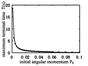
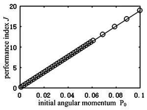
As can be seen from Figure 5, with the increase of the initial angular momentum, the maximum allowable flight stage continues to decrease. When , the maximum duration shows an exponential decreasing trend. Due to the decrease in the duration of the flight phase, the height of the hopping (the maximum height of the robot’s center of mass during the flight phase) decreases, and the foot may collide with the ground. When , the flight phase can be arbitrarily taken. It can be seen from Figure 6 that with the increase of the initial angular momentum, the performance index, i.e. energy consumption, increases accordingly, and the change of energy consumption and initial angular momentum is approximately in a straight line. It is can be drawn a conclusion that the existence of initial angular momentum is a very unfavorable factor for motion planning. Therefore, in the control process, the initial angular momentum at the take-off should be zero as far as possible.
|
| Figure 5. Maximum flight time vs. initial angular momentum |
|
| Figure 6. Performance index vs. initial angular momentum |
2) The effect of flight time on hopping performance
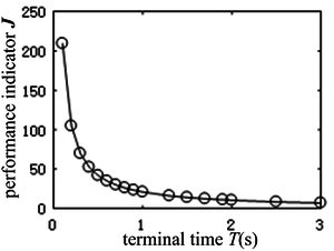
In this section, the impact of flight time on hopping performance is discussed when initial angular momentum equals 0. Figure 7 shows the curve of performance indicator as a function of flight time. When the initial angular momentum is zero, the flight time can be arbitrarily selected. It can be seen that as the flight time increases, the performance indicator decreases, that is, the energy consumption decreases, and changes sharply within 0.5 seconds. As time increases, the robot has sufficient time to change the position of the joint angle, resulting in a smaller input and lower energy consumption. But at the same time, as time increases, the height of the hopping increases, and the vertical velocity of the center of mass at take-off also increases, requiring the robot to provide greater force . Therefore, it is necessary to comprehensively measure and select the appropriate time.
|
| Figure 7. Performance indicator vs. flight time |
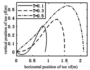
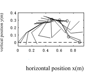
From Figure 8, it can be seen that as the flight time decreases, the movement distance of the hopping robot’s center of mass in the horizontal direction decreases, and the height in the vertical direction decreases, resulting in the robot’s foot height being less than 0 in the first 0.02 seconds, indicating a collision between the foot and the ground. Figure 9 shows the posture diagram. It can been seen that at the end of the flight phase the foot of the hopping robot touch the ground. It indicates that the flight phase is over. The negative height of the robot’s foot during flight phase indicates a collision between the robot’s and the ground.
|
| Figure 8. Trajectory of tip of the foot at different flight times |
|
| Figure 9. Posture diagram during flight phase at |
5. Conclusions
In this paper the energy optimal motion planning problem of the hopping robot with three links in the flight phase is investigated. First, the conservation equation of angular momentum of the hopping robot in the flight phase is established which is a non holonomic constraint. Then, the energy consumption of the robot during the flight phase is selected as the optimization goal. Given the initial and terminal positions, the Gaussian pseudospectral method is used to solve the optimal control problem. The conclusion can be drawn as follows:
1) The initial angular momentum has a great impact on the performance of the hopping robot. The larger the initial angular momentum is, the smaller the maximum allowable flight time of the robot will be. When the initial angular momentum is zero, the flight time can be chosen arbitrarily;
2) When the initial angular momentum is zero, the longer the flight time is, the smaller the energy consumption is, and the greater the flight distance and height are. However, the higher the velocity of the robot in the vertical direction of the center of mass at flight, the greater the force required by the robot. The smaller the flight time, the smaller the flight distance and altitude, and the less force required for flight. However, the energy consumption increases, and the robot’s foot may collide with the ground. So it is necessary to comprehensively measure and select a suitable time for flight.
References
[1] Raibet M.H. Legged robots that balance. Cambridge, the MIT Press, 1986.
[2] Ahmadi M., Buehler M. Controlled passive dynamic running experiments with the ARL-Monopod II. IEEE Transactions on Robotics, 22(5):974-986, 2006.
[3] Hyon S.H., Emura T., Mita T. Dynamics-based control of a one-legged hopping robot. Proceedings of the Institution of Mechanical Engineers, Part I: Journal of Systems and Control Engineering, 217(2):83-98, 2003.
[4] Park H.W., Wensing P.M., Kim S. High-speed bounding with the MIT Cheetah 2: Control design and experiments. International Journal of Robotics Research, 36(2):167-192, 2017.
[5] Terry P., Piovan G., Byl K. Towards precise control of hoppers: Using high order partial feedback linearization to control the hopping robot FRANK. IEEE 55th Conference on Decision and Control (CDC) ARIA Resort & Casino, Las Vegas, USA, 6669-6675, 2016.
[6] Haldane D.W., Yim J.K., Fearing R.S. Repetitive extreme-acceleration (14-g) spatial jumping with Salto-1P. 2017 IEEE/RSJ International Conference on Intelligent Robots and Systems (IROS), 3345-3351, 2017.
[7] Vermeulen J. Trajectory generation for planar hopping and walking robots: An objective parameter and angular momentum approach. McGill University, Department of Mechanical Engineering, 2004.
[8] Li Z., Huang Q., Li, K. Duan X. Stability criterion and pattern planning for humanoid running. Proceedings of the 2004 IEEE International Conference on Robotics & Automation, 1059-1064, 2004.
[9] Wu T.Y., Yeh T.J., Hsu B.H. Trajectory planning of a One-Legged robot performing a stable hop. The International Journal of Robotics Research, 30(8):1072-1091, 2011.
[10] Shabestari S.S., Emami M.R. Gait planning for a hopping robot. Robotica, 34(8):1822-1840, 2016.
[11] Ahn D.H., Cho B.K. Optimal periodic hopping trajectory generation for legged robots. IEEE/ASME International Conference on Advanced Intelligent Mechatronics (AIM), Auckland, New Zealand, 1263-1268, 2018.
[12] Rehman F., Ahmed M.M., Memon N.M., Riaz M. Time-varying stabilizing control for a hopping robot model during the flight phase. 2006 IEEE International Multitopic Conference, Islamabad, Pakistan, 400-403, 2006.
[13] Guo Q., Macnab C., Pieper J. Hopping with nearly-passive flight phases. 2008 IEEE Conference on Robotics, Automation and Mechatronics, Chengdu, China, 743-748, 2008.
[14] Yong E.-M., Chen L., Tang G.-J. A survey of numerical methods for trajectory optimization of spacecraft (in Chinese). Journal of Astronautics, 29(2):397-406, 2008.
[15] Xu S.-B., Li S., Cheng B. Theory and application of Legendre pseudo-spectral method for solving optimal control problem (in Chinese). Control and Decision, (12):2113-2120 , 2014.
[16] Xingsheng G., Kaijie C. Path planning of free floating space robot using Legendre pseudospectral method (in Chinese). Chinese Journal of Theoretical and Applied Mechanics, 48(4):823-831, 2016.
Document information
Published on 18/09/23
Accepted on 31/08/23
Submitted on 05/06/23
Volume 39, Issue 3, 2023
DOI: 10.23967/j.rimni.2023.09.002
Licence: CC BY-NC-SA license
Share this document
Keywords
claim authorship
Are you one of the authors of this document?
