Abstract
In this study, based on the dynamic characteristics of radial gates, a nonlinear differential equation of motion for a radial gate arm is derived. The excitation conditions of both principal and subharmonic parametric resonance cases are obtained by using multi-scale and numerical methods. The parameter analysis reveals the following: In comparison to the analytical calculation method (e.g., Multi-scale) of dynamic instability region division, this method effectively analyzes the parametric vibration of radial gates in terms of the end moment, vibration duration, and amplitude. The vibration amplitudes of the arm increase with an increase in its length and excitation amplitude as well as a decrease in the arm inclined angle. Moreover, the parametric resonance excitation is facilitated, and the resonance region becomes larger with an increase in the initial end moment. Comparing with damping effect, vibration response of the arm is mainly affected by the nonlinear behavior in system. Therefore, the energy transfer method (e.g. Add tuned mass dampers) should be taken into account in vibration control.
Keywords: Radial gate, parametric vibration, multi-scale method, parameter analysis
1. Introduction
A radial gate is a main regulating structure employed in hydraulic engineering, and its stability is directly related to the safe operation of a reservoir. However, the dynamic instability mechanism of radial gates has not been elucidated thus far, and as a result, the existing structures that are constructed without appropriate anti-vibration design are vulnerable. Even if such structures are designed for anti-vibration performance, their design may not comply with current design code [1] and thus may exhibit deficient anti-vibration performance. In recent years, several engineering practices, such as Wachi Dam (1967) in Japan and the Folsom Dam (1995) in the United States, have shown that radial gates will produce different degrees of vibration and even damage structure considerably to flow-induced excitation when the gates were partially opened [2-3]. The lightness, slenderness, and flexibility of the arm render the structure to vibration and dynamic instability easily, when subjected to water loads. Moreover, the increase of water level will reduce the structural frequency, this characteristic indicates that the radial gate should be highly vulnerable under high water head [4]. Consequently, the dynamic stability of the radial gate arm has become a crucial issue with many influence factors that needs to be resolved in both the design and operation stages [5]. According to excitations such as cavity flow, Kármán vortices and special hydrodynamic load, the vibration patterns of the gates can be categorized as follows: forced vibration, self-excited vibration, and parametric vibration. Based on the elongated nature of radial gate arms as mentioned above, among the various types of gates, the parametric vibration only appears in radial gates. The problems of parametric vibration are encountered in many branches of physics and engineering, have been studied extensively, such as in cable structures [6], beam structures [7], plate and shell structures [8], and coupled models of multi-member interaction [9]. In 1980s, Zhang [10] observed the phenomenon of parametric vibration during gate operation in dynamic water, considered it as one of the important causes of dynamic instability in the arm through engineering failure examples, and proposed a concise analytical calculation method. Subsequently, there are thought-provoking researches that have been carried out on the division of the dynamic instability region [11]. Although this region can be used to determine whether parametric resonance occurs or not, it does not yield the response amplitude at an arbitrary time. In general, the radial gate is subjected to flow-induced load for a relatively short period of time, and the arm amplitudes continue to fluctuate within a narrow range without the magnification factor tending to infinity. Hence, the method of dynamic instability region may not be an accurate criterion for defining the dynamic instability without considering the time factor. Recently, Zhang and Xie [12] investigated the unstable behavior of nonlinear systems in the radial gate arm under certain dynamic loads and proved the necessity to analyze the stability of radial gate in terms of the excitation amplitude and time duration.
In this study, according to the mechanical characteristics of the radial gate, with by completely considering the geometric nonlinear factors caused by the bending moment and large displacement at the high head, the nonlinear differential equation of motion for an arm is derived. The stability of parametric vibration is obtained using multi-scale and numerical methods. Moreover, the effects of excitation factors (water head, frequency, time, and amplitude) and structural factors (inclined angle, length, and damping) on the vibration response of the arm are quantitatively analyzed.
2. Derivation of the nonlinear differential equation of motion
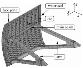
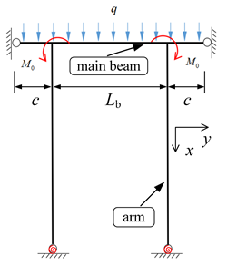
Three dimensional overview of the radial gate is shown in Figure 1, the gate contains a face plate to retain water, two major crossbeams, four inclined arms with box-sectional area, major vertical beams and minor beams [13]. The anchor of radial gate arm is attached to piers, which can be regard as a semi-rigid connection. In accordance with Chinese design code SL74-2013 [1], the structure can be simplified as an extended beam, both ends constrained by water seal in direction, and assembled with arms by welding. The water pressure can pass to piers through face plane, main beams and arms, while, the load acting on main beam can be considered as uniform hydrostatic pressure by equivalent calculation (Figure 2). Then on the base of these, further analyze the arm vibration under local coordinate, the model as shown in Figure 3, with the length of the arm , the transverse displacement , flow-induced excitation frequency , the tangential hydrostatic force , and the additional tangential hydrodynamic force . Due to parametric vibration is induced by harmonic load, so can be assumed as the function of harmonic displacement of flow excitation .
|
| Figure 1. Three dimensional overview of the radial gate |
|
| Figure 2. The main frame of in-plane radial gate |

|
| Figure 3. Vibration model of a radial gate arm |
The following basic hypotheses are made before establishing the equation of motion for radial gate arms:
(1) Material properties: based on previous hydraulic experiments on full-scale or model gates, the arm, which are considered homogeneous and isotropic, and always behave elastically under design loads, even fails in a predominantly elastic mode (sway-type failures). For convenience and safety, most study of hydraulic experiments, suppose the whole structure work in elastic state.
(2) Element type: due to the ends of arm are restricted by major crossbeams and piers, respectively, and its length is much larger than dimensions of cross-section, so the arm can be regarded as a Bernoulli-Euler beam, the torsion and shear effect are negligible.
Recently, Zhang et al. proposed a non-moment design method for eliminating end bending moment of vertical main frame ( plane) [14]. This method reduces out-of-plane eccentric compression on the arm and improve the overall stability bearing capacity. But the study of in-plane ( plane) layout scheme about end bending moment has not been reported thus far, while Hu et al. examined that the effect of in-plane initial end bending moment cannot be neglected from prototype observation [15]. According to the above researches, in-plane vibration of arm is discussed in this work. The relation between the deflection and moment can be written as:
|
|
(1) |
where, according to design code (SL74-2013), in order to ensure the safety of the calculation results, the major crossbeam is assumed as a double cantilever beam and .
In order to keep derivations in this study clear, according to the relatively simple boundary conditions without loss of generality (Figure 2). The sag of the arm is expressed as follows:
|
|
(2) |
where denotes the flexural rigidity and the rotational stiffness of semi-rigid connection.
The equation of motion for the arm is as follows:
|
|
(3) |
where represents the lagrange coordinate by the arc length, is the mass per unit length of the arm and the damping coefficient . When , the arm is upright, same as layout of Figure 2.
According to the geometric deformation and stress state of the arm model, the following results are obtained:
|
|
(4) |
where and represent the axial force and additional axial hydrodynamic force, respectively.
By Taylor formula, Equation (5) is expanded at :
|
|
(5) |
According to static force equilibrium equation of radial gate arm:
|
|
(6) |
Substituting Equations (4), (5) and (6) into Equation (3), the following equation is obtained:
|
|
(7) |
The length variation of micro-segment ds' is assumed as follows:
|
|
(8) |
where is the longitudinal displacement.
Substituting Equation (8) into Equation (4) and neglecting the quadratic term of longitudinal strain gives the following equation:
|
|
(9) |
As , Equation (9) can be rewritten as follows:
|
|
(10) |
The boundary conditions for generalized displacements vector (Figure 2) are written as:
|
(11) |
Satisfying the boundary conditions (11), by separation of variables, the vibration mode of the arm can be expressed as:
|
|
(12) |
where is the displacement amplitude. According to early analysis, Liu et al. pointed out that, for radial gate arm vibration induced by flow excitation, the first mode is dominated [11]. Hence, We can use the single mode approximation with neglecting modal interaction.
The axial hydrodynamic force of radial gate arm can be expressed as follows:
|
|
(13) |
where .
Substituting Equations (2), (12) and (13) into Equation (7) yields the following equation:
|
|
(14) |
Then, according to the Galerkin method, the equation of motion is obtained as follows:
|
|
(15) |
where
, , ,
,
,
,
,
.
where is the damping ratio, corresponds to the first-order natural frequency and is the arm parameter of the end moment.
In comparison to the classical parametric vibration models [2,11-12], this model is highly comprehensive and it reflects the characteristics of the parametric vibration of radial gates with greater accuracy.
3. Stability analysis
In the present investigation, as both the stretching of the arm and the flow excitation are small, the nonlinear terms and the parametric excitation terms are smaller than the linear terms. Therefore, the method of multiple scales is applied to Equation (15) to asymptotically describe the slow dynamics of the model [16-17]. To weaken the nonlinear terms, the following substitutions are made:
|
(16) |
where ε is a small bookkeeping parameter. Then, Equation (15) can be rewritten as:
|
|
(17) |
Supposing the solution to Equation (17) can be expressed as:
|
|
(18) |
where , , . Substituting Equation (18) into Equation (17) and letting the coefficients , and equal zero, the following equations are obtained:
|
|
(19) |
|
|
(20) |
|
|
(21) |
The complex solution to Equation (19) can be assumed as:
|
|
(22) |
where is the complex conjugate of .
Substituting Equation (22) into Equation (20), one gets:
|
|
(23) |
where indicates the complex conjugate part. Eliminating the secular terms yields:
|
|
(24) |
Substituting Equations (22) and (24) into Equation (21) leads to:
|
|
(25) |
Through practical observation [10], when excitation frequency approaches 2 times of the structure frequency , the parametric resonance may occur. A detuning parameter σ is introduced to quantify the deviation of from 2 and is described by:
|
|
(26) |
Substituting Equation (26) into Equation (25) and eliminating secular terms yields:
|
|
(27) |
Then, by expressing the function in the polar form as:
|
|
(28) |
where and are real functions. By substituting this transformation into Equation (27), and separating the resulting real and imaginary parts yield:
|
|
(29) |
|
|
(30) |
where . The stationary solution equation αs and γs can be obtained from Equations (29) and (30) by letting . The vibration amplitude can be expressed as:
|
|
(31) |
For αs is a real number, from Equation (31), the stability boundary is given by:
|
(32) |
or
|
(33) |
From Equations (32) and (33), emerging conditions of subharmonic parametric resonance can be obtained and many parameters like axial force, length of arms, etc. affect the structural motion stability region. It is a kind of way to get the dynamic instability region. But the stable solutions are functions of structural characteristics, which are not including effect of time factor. Therefore, the numerical method is further adopted to analyze.
4. Numerical analysis
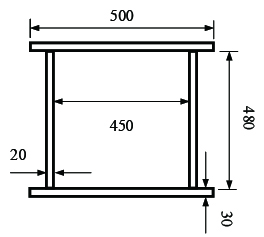
In this section, the nonlinear responses of the radial gate arm are investigated. As a example, considering a radial gate arm with box-section, the cross-sectional dimensions are shown in Figure 4. The arm length m, mass per unit length kg/m, and modulus of elasticity GPa.
|
| Figure 4. Arm section (unit: mm) |
Applying the fourth-order Runge–Kutta method to Equation (15), the radial gate arm subjected to the parametric excitation are investigated and the effects of the excitation and structural factors are evaluated.
4.1 Effect of water head
According to the Chinese and American codes, the layout of the main beam adopts equivalent load method, and the hydrostatic force is a function of water head. Table 1 summarizes the Chinese super high head radial gates ( m). We first chose the initial disturbance {−4} m, excitation amplitude m, time s, damping coefficient , and water head as a basic case. Figure 5 shows the influence of water head on the vibration amplitudes, denotes the ratio of the external excitation frequency to the natural frequency.
| Engineering | Location | Size of face plane width-height (m) |
Water head (m) | |
|---|---|---|---|---|
| 1 | Xiaowan | Lantsang | 5.07.0 | 163.00 |
| 2 | Shuibuya | Qing River | 6.07.0 | 154.00 |
| 3 | Xiaolangdi | Yalong River | 4.84.8 | 140.00 |
| 4 | Jinping-I | Yalong River | 5.06.0 | 133.00 |
| 5 | Laxiwa | Yellow River | 4.06.0 | 132.00 |
| 6 | Pubugou | Dadu River | 6.58.0 | 126.28 |
| 7 | Nuozhadu | Lantsang | 5.0×8.5 | 126.00 |
| 8 | Tianshengqiao-I | Pearl River | 6.4×7.5 | 120.00 |
| 9 | Dongjiang | Dong Jiang Lake | 6.4×7.5 | 120.00 |
| 10 | Longyangxia | Yellow River | 5.0×7.0 | 120.00 |
| 11 | Xiluodu | Jinsha River | 6.0×6.7 | 105.50 |
| 12 | Jiangpinghe | Loushui River | 6.0×6.0 | 105.14 |
| 13 | Longtan | Hongshui River | 5.0×8.0 | 90.00 |
| 14 | Dagangshan | Dadu River | 6.0×6.6 | 83.00 |
| 15 | Goupitan | Wujiang River | 10.0×9.0 | 81.00 |
When the principal parametric resonance occurs, the amplitude of the arm increases with the water head, and the maximum displacement reaches 0.57 m. In the case of subharmonic parametric resonance, the change is contrasting, and the maximum amplitude is 0.18 m. Overall, both the types of parametric resonance responses change slowly, so supposes the axial hydrostatic force generated by 80 m water head in further analysis.

|
| Figure 5. Vibration amplitude–water head curves |
4.2 Effects of excitation frequency ratio and initial end bending moment
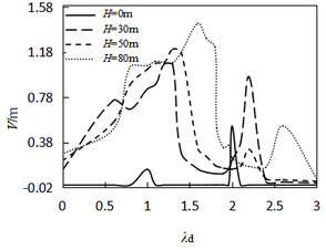
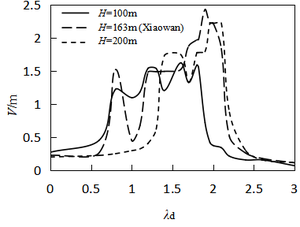
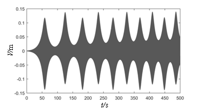
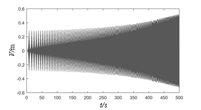
Figure 6 depicts the relationship curves plotted between the vibration amplitude and the excitation frequency ratio when subjected to the initial end bending moment of different water heads. As shown in the figure, at , the peak value of parametric resonance only appears at and . This phenomenon conforms to the current design code “Design Code for Steel Gate in Water Resources and Hydropower Projects (SL74-2013)” (2013). Figure 7 shows that when the initial end bending moment is not considered, the beat vibration phenomenon can be observed, and the beat amplitude value increases over time at the subharmonic parametric resonance. However, considering the initial end bending moment (Figure 6), the amplitude peak shifts and the arm response amplitudes increase with the initial end bending moment level and the resonance region become larger, which facilitates parametric resonance excitation. According to the design retaining water height of the gate, 80 m is the critical value between high head gates and super high head gates, and maximum existing design head is 163 m (Table 1). The maximum displacements of parametric resonance are 1.44 m and 2.20 m at water heads of 80 m and 163 m, respectively. Through the above analysis, it is further elucidated that the parametric resonance excitation condition given in Chinese code is a special case in the parametric resonance region, which only considers the parametric resonance occurring at nearly twice the natural frequency. In order to obtain a higher accuracy response of the arm, the proposed calculation method of the instability regions in this study should be adopted.
|
|
| (a) m | (b) m |
| Figure 6. Vibration amplitude–excitation frequency ratio curves | |
|
|
| (a) | (b) |
| Figure 7. Displacement time–history curves | |
4.3 Effect of excitation amplitude
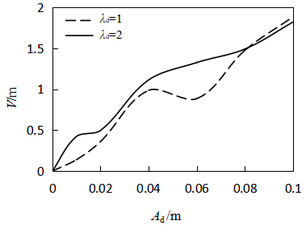
Figure 8 shows the relationship curve between the displacement and the excitation amplitude. The graph shows that when parametric resonance occurs, the displacement response is closely related to the excitation amplitude. The response increases nonlinearly with an increase in the excitation amplitude. When the excitation amplitude is less than 0.08 m, the subharmonic parametric resonance response is greater than the principal parametric resonance response. On the other hand, when the excitation amplitude is greater than 0.08 m, both the parametric resonance responses are almost equal. When the excitation amplitude is less than 0.01 m, the arm swings in a smaller range, making it difficult to form a destructive vibration. Hence, the response of the arm should be completely considered with respect to the factor of excitation amplitudes.
|
| Figure 8. Vibration amplitude–excitation amplitude curves |
4.4 Effect of inclined angle
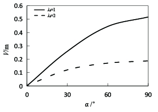
The effect of inclined angle on the vibration amplitude is presented in Figure 9. The amplitude displacement increases significantly at subharmonic parametric resonance with the angle. However, at parametric resonance, when the angle is less than 45 degrees, the amplitude increases rapidly and then remains steady. Hence, the inclined angle should be considered along with the displacement constraint in the design of radial gates.
|
| Figure 9. Vibration amplitude–inclined angle curves |
4.5 Effect of arm length and excitation time
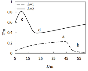
According to the characteristics of conventional radial gate and special planar radial gate, as mentioned in the study by Chen and Yan [18], the arm length from 5 to 25 m is examined in this study. The relationship curve is plotted between the amplitude and the length of arm, as shown in Figure 10.
|
| Figure 10. Vibration amplitude–length curves |
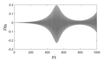
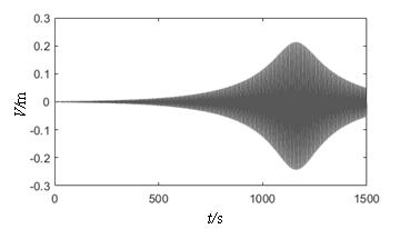
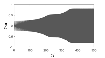
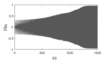
It can be found that the calculated results are not in agreement with the description of the conventional partitioning method for unstable regions In the past review, with an increase in the length of the arm, its flexibility and response amplitude should increase simultaneously. However, the inflection point appears in Figure 10, and a nonlinear curve dependence is noted. Then, the time history analysis at a, b, c, and d on both sides of the inflection are given in Figure 11. When the arm length is greater than 45 m and 20 m at λd = 1 and λd = 2, a longer excitation time is needed to reach the peak response. This result proves that the gate may not show a strong vibration at the initial stage of the local opening operation, while the vibration amplitude will become considerably higher across time until the structure reaches integral instability failure. The results also prove that it is not advisable to ignore the time factor in the conventional design.
From the above analysis, it is noted that the time factor of the local opening should be considered in the initial design stage. Meanwhile, in the stages of completion and operation, the corresponding guidelines of local opening range and opening–closing time should be given in detail according to the vibration analysis results in a project. It is practical to choose the length of radial gate arm to be less then 20 m in 500 s according to the case presented in this exploration.
|
|
| (a) λd= 1, L = 45 (Vmax= 0.2291) | (b) λd= 1, L = 60 (Vmax= 0.2427) |
|
|
| (c) λd= 2, L = 10 (Vmax= 0.8116) | (d) λd= 2, L = 20 (Vmax= 0.9604) |
| Figure 11. Displacement time-history curves | |
4.6 Effect of damping
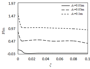
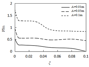
Figure 12 illustrates the relationship between amplitude and damping ratio under different excitation amplitudes. As shown in the figure, the amplitude nonlinearly decreases with an increase in the damping ratio. Furthermore, the amplitude decreases rapidly at λd = 1, ξ < 0.01, and then remains steady. The damping decrement at λd = 2 is slightly higher than that at λd = 1. Overall, the damping effect to vibration control is not very obvious, once the parametric resonance excitation is achieved, the resonance amplitudes are significantly affected by the nonlinear term of system rather than the damping coefficient. Hence, when an energy transfer method, such as adding tuned mass dampers, is employed, the vibration suppressed effectiveness is better.
|
|
| (1) λd=1 | (b) λd=2 |
| Figure 12. Vibration amplitude–damping ratio curves |
5. Conclusions
This paper presents the nonlinear parametric vibration of radial gates. The nonlinear differential equation of motion for the radial gate arm is derived by considering the geometrically nonlinear. Furthermore, the stability and vibration response of principal and subharmonic parametric resonance cases are investigated by using multi-scale and numerical methods. At the same time, the numerical analysis overcomes the limitations of the former methods, in which the dynamic instability regions are divided without considering the effects of response amplitude and time. The results are discussed as follows:
- The change in the hydrostatic force caused by the water head has a negligible effect on the parametric vibration, while the resonance region broadens with an increase in the initial bending moment.
- An increase in amplitude response leads to an increase in both the excitation amplitude and arm length and a decrease in the inclined angle.
- The vibration amplitude becomes significantly higher with time. Therefore, the time factor should be considered in the design and operation stages.
- Comparing with damping effect, the vibration response mainly depends on the nonlinear behavior. Thus, the energy transfer method should be adopted to suppress the vibration.
Acknowledgements
This research is supported by National Natural Science Foundation of China (Grant No. 51179164 and 51478354).
References
[1] CMWR (China Ministry of Water Resources). Design code for steel gate in water resources and hydropower projects (SL74-2013). China Water & Power Press, Beijing, 2013.
[2] Niu Z.G., Li T.C. Research on dynamic stability of steel radial gates. In Earth and Space, Long Beach, pp. 1-8, 2008.
[3] Oh L.S., Hoje S., Won K.J. Flow-induced vibration of a radial gate at various opening heights. Eng. Appl. Comp. Fluid, 12:567-583, 2018.
[4] Brusewicz K. Sterpejkowicz-Wersocki W., Jankowski R. Modal analysis of a steel radial gate exposed to different water levels. Arch. Hydro Eng. Environ. Mech., 64:37-47, 2017.
[5] Wang Z.Z., Zhang X.C., Liu J.L. Advances and developing trends in research of large hydraulic steel gates. J. Hydroelectr. Eng., 36:1-18, 2017.
[6] Demsic M., Uros M., Lazarevic A.J., Lazarevic D. Resonance regions due to interaction of forced and parametric vibration of a parabolic cable. J. Sound. Vib., 447:78-104, 2019.
[7] Zhang X., Peng J., Wang L. Parametric resonances in the two-to-one resonant beams on elastic foundation. Nonlinear Dynam., 77:339-352, 2014.
[8] Franzini G.R., Pesce C.P., Gonçalves R.T., Fujarra A.L.C., Mendes P. (2018). An experimental investigation on concomitant vortex-induced vibration and axial top-motion excitation with a long flexible cylinder in vertical configuration. Ocean Engineering, 156:596-612, 2018.
[9] Wei M.H., Lin K., Jin L., Zou D.J. Nonlinear dynamics of a cable-stayed beam driven by sub-harmonic and principal parametric resonance. Int. J. Mech. Sci., 110:78-93, 2016.
[10] Zhang J.G. Summary on the study of gate vibration in China. Water Power, 11:38-44, 1985.
[11] Liu J.L., Wang Z.Z., Fang X., Fang H.M. (2011) Dynamic instability mechanism and vibration control of radial gate arms. Appl. Mech. Mater., 50:309-313, 2011.
[12] Zhang J., Xie Z.X. Nonlinear vibration and chaos phenomena of arm structures in radial gate. Water Power, 50:309-313, 2011.
[13] Cai K., Zhang, C. An optimal construction of a hydropower arch gate. Adv. Mater. Res., 346:109-115, 2011.
[14] Zhang X.C., Wang Z.Z., Sun D.X. Research on rational layout of strut arms of tainter gate in vertical frame. Revista Internacional de Métodos Numéricos para Cálculo y Diseño en Ingeniería, 34:1-6, 2018.
[15] Hu M.S., Yang Z.Z., Xu J., Zhang B. Modal parameter identification of radial gate based on stochastic subspace method. Water Resour. Power, 33:164-167, 2015.
[16] Nayfeh A.H., Mook D.T. Nonlinear Oscillations. Wiley Publisher, New York, 1979.
[17] Chen Y.S. Nonlinear Vibration. Higher Education Press, Beijing, 2002.
[18] Chen F.Z., Yan G.H. The key technology research on Chinese special type sluice. Hohai University Press, Nanjing, 2015.
Document information
Published on 22/01/20
Accepted on 10/12/19
Submitted on 05/06/19
Volume 36, Issue 1, 2020
DOI: 10.23967/j.rimni.2019.12.004
Licence: CC BY-NC-SA license
Share this document
claim authorship
Are you one of the authors of this document?
