Abstract
Architectural heritage conservation is an important field in architectural research. The Hui-style vernacular dwelling is an essential architectural heritage of China. Its hollow wall system, with horsehead-like upper corners, is a distinct architectural feature that is worth preserving. However, the thermal performance of the hollow wall is relatively poor by todays standard. The current study developed a novel approach, whereby foam concrete was used to fill the voids inside the hollow wall to improve its thermal resistance. This approach was deemed cost effective, easy to learn, and capable of preserving the architectural integrity of the wall. Different types of foam concrete were prepared and tested. Testing results showed that the material properties of foam concrete are suitable for thermally upgrading the hollow wall system. Climate chamber testing was conducted to investigate the effectiveness of the proposed thermal upgrading strategy. The testing results suggested that filling the voids with foam concrete can effectively improve the overall thermal resistance of the hollow wall system by 24%, which is almost equal to the overall thermal resistance when using the more expensive commercial inorganic stucco system.
Keywords
Hui-style vernacular dwelling ; Thermal upgrade ; Foam concrete ; Architectural heritage
1. Introduction
1.1. Hui-zhou region and Hui-style vernacular dwelling
China is a country with a vast territory, significantly different climate, and diverse cultures and ethnic groups. All these, combined with its long history, have created a range of vernacular dwellings—from the Forbidden City for the royal family, to the adobe houses in south-east China. Both Chinese and international scholars have shown interest in studying these vernacular Chinese dwellings and villages; typical examples are the works by Lu (2004) , Knapp (1992) , and Steinhardt (1990) .
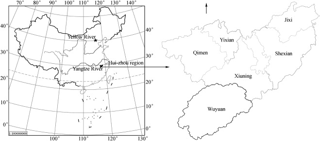
Hui-style vernacular dwellings refer to the traditional houses in the old Hui-zhou region, which encompasses the southern part of Anhui Province and the north-eastern part of Jiangxi Province. A distinct culture has long been formed in the Hui-zhou region and influenced many other regions in China. Fig. 1 shows the geographical location of the Hui-zhou region and its six counties.
|
|
|
Figure 1. Hui-zhou region in China and its six counties. |
According to the current building energy efficiency design code (GB50176-93, 1993), the Hui-zhou region belongs to the hot summer/cold winter climate zone. In this climate zone, the weather is hot and humid in summer, and it can be below freezing point in winter. According to the weather data provided by the World Meteorological Organization weather station 585310 located in Tunxi, one of the six counties in the Huizhou region, the daily average temperature in July and August is 27.5 °C, and 5.7 °C in January and February. The Hui-zhou region is mountainous, and fertile land has been in short supply throughout the history. Therefore, the typical Hui-style villages are compact to save land. These villages were designed and built according to the principles of Feng-shui . In China, Feng-shui is a traditional body of knowledge that deals with the relationship between buildings and their surrounding environment. One may argue that Feng-shui has superstitious elements; however, that topic is beyond the scope of the present paper.
1.2. Wall materials and construction in Hui-style vernacular dwellings
The vernacular dwellings in Hui-zhou have distinct architectural characteristics, with their exterior walls deemed the most noteworthy. The exterior wall in Hui-style vernacular dwellings uses various locally available construction materials. Taking advantage of what is available locally is natural because it reduces the cost of transporting materials to the mountainous Hui-zhou region. Among various wall materials, the fired-clay brick with a dark greenish color is the most common (Fig. 2 (a)). A local granite-type natural stone (Fig. 2 (b)) is widely used to construct the base of the wall, sometimes being below grade to act as a strip footing. Small pebbles are another convenient material found in many rivers, large or small, in the Hui-zhou region. Given their various sizes, small pebbles are perfect fillers to be used together with the natural stones to seal the holes in the wall (Fig. 2 (c)). Cementitious mortar was unavailable until very recently. Its replacement in the Hui-style vernacular dwelling is mud or soil mixed with water. Mud glues bricks, natural stones, and pebbles together, and offers better bearing. The wall systems built using these materials have passed the test of time; there are thousands of Hui-style vernacular dwellings that are well over 100 years old and are still structurally sound.
|
|
|
Figure 2. Common wall materials in Hui-style vernacular dwellings: (a) clay brick, (b) natural granite stone, and (c) pebble. (For interpretation of the references to color in this figure legend, the reader is referred to the web version of this article.) |
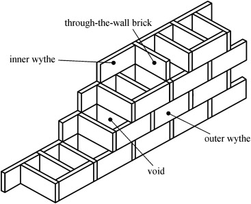
The most common exterior wall system in the Hui-style vernacular dwelling is the so-called “hollow wall”. This wall type has an outer wythe of one layer of clay brick and an inner wythe of another layer of clay brick. Clay bricks, usually cut in half, are inserted through the wall to act as diaphragm. Therefore, the actual thickness of the wall is half the width of a clay brick. The term “hollow wall” is derived from the presence of many voids formed inside. Sometimes, these voids are filled with mud for multiple purposes, including increasing the integrity of the wall, and sealing cracks and small holes in the wall. In newly built Hui-style vernacular dwellings, mud is not used anymore to save cost and speed up construction. Fig. 3 shows a 3D view of the hollow wall construction.
|
|
|
Figure 3. A 3D view of the hollow wall construction in the Hui-style vernacular dwellings. |
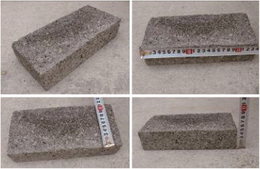
In newly built Hui-style vernacular dwellings, traditional fired clay bricks are replaced by modern masonry. A common type of brick masonry (Fig. 4 ) is made of aggregate, cement, and water, and hardened by natural curing, without baking or kiln firing involved in the manufacturing process. The aggregate involves various materials, including industrial solid wastes such as cinders. This type of brick masonry is relatively inexpensive and, thus commonly used by Hui-zhous local residents to build their houses.
|
|
|
Figure 4. Brick masonry made of industrial solid wastes, cement, and water. |
1.3. Thermal performance of traditional Hui-style vernacular dwellings
As discussed previously, the Hui-zhou region is located in the hot summer/cold winter climate zone. Hence, both heating and cooling are needed to maintain a comfortable indoor thermal environment. In the old days when modern building heating and cooling technology was unavailable, the Hui-style vernacular dwellings depended on natural cooling in summer by adopting passive design techniques, such as shading, water cooling, and landscaping. These traditional cooling design techniques are still valuable in todays architectural design. Literature discussing summer cooling in Chinese vernacular dwellings can be found in international journals such as Lin et al. (2004) .
Local residents in the Hui-zhou region have been using the fire basin for heating in winter for a long time (Fig. 5 ). The fire basin can be considered as the traditional counterpart of todays personalized heating system. As unit air-conditioning systems, both for cooling and heating, become common, many Hui-zhou residents buy and install them in their dwellings. Hence, the thermal performance of the exterior wall system becomes a key factor in maintaining indoor thermal comfort and in controlling the energy consumption. The current paper discusses a method to improve the thermal performance of the exterior wall system in the Hui-style vernacular dwellings without drastically changing the traditional hollow wall construction.
|
|
|
Figure 5. A traditional fire basin and its user. |
1.4. Foam concrete
Foam concrete is a novel type of lightweight insulation material consisting of Portland cement paste or cement filler matrix (mortar), in which a homogeneous air-void or pore structure is created by introducing an air-suitable foaming agent (Ramamurthy et al ., 2009 ; Kan and Demirboga, 2009 ). Foam concrete can be designed to have any density ranging from 400 to 1600 kg/m3 . Foam concrete is self-compacting, lightweight, and has low strength (between 1 and 10 MPa) and excellent thermal properties (Lu, 2004 ; Marrs and Bartos, 1996 . It is suitable for a variety of applications, such as grade filling and enclosure insulation. There has been a renewed interest in using industrial wastes, such as fly ash, incinerator bottom ash, recycled glass, and foundry sand, in foam concrete (Jones and McCarthy, 2005 ; Panyakapo and Panyakapo, 2008 ). In the present study, foam concrete was selected as a filling material for the voids in the Hui-style hollow wall to upgrade its thermal performance.
2. Methodology
2.1. Strategy for thermally upgrading the Hui-style exterior wall system
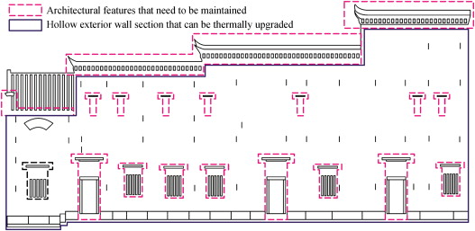
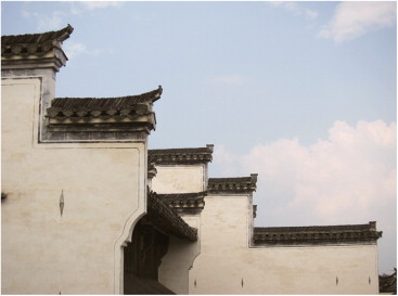
The Hui-style vernacular dwelling is an important vernacular architecture in China. Its distinct architectural features must be maintained when upgrading its thermal performance. Fig. 6 shows an elevation of a typical Hui-style exterior wall system, with the most important architectural features marked. These walls are usually built higher than the roof to curtail the incidence of fire curtain off fire and prevent it from spreading. This specification is of utmost importance to Hui-style villages because they are densely built. In addition, the dwelling units are often right next to each other and are therefore fire-spread-prone. Esthetically, the walls have horsehead-like upper corners and, therefore, are often called “horsehead walls” (Fig. 7 ). The horsehead wall is the most distinct architectural feature of the Hui-style vernacular dwelling, and has a profound influence on the architectural style in other regions in China.
|
|
|
Figure 6. Elevation of a Hui-style exterior wall and its distinct architectural features that need to be maintained. |
|
|
|
Figure 7. Horsehead walls as a distinct architectural feature of the Hui-style vernacular dwellings. |
In addition to the horsehead-like upper corners, wooden windows and doors that are often decorated with complex and fine carvings are another distinct architectural feature of the Hui-style exterior wall system. Although a modern window with low-E double pane glazing and thermally superior frame is better in terms of thermal performance, it cannot be used to replace the traditional wooden windows because doing so may impair the cultural and architectural integrity of the wall. The principle of conserving the heritage is the priority here. Hence, only the hollow wall section below the eaves and between the wooden windows and doors, as shown in Fig. 5 , is suitable for thermal upgrading. The approach discussed in the current paper is to fill the voids inside the hollow wall with foam concrete to increase the overall thermal resistance (R -value) of the wall and improve the energy efficiency of the dwelling. This method offers at least three advantages. First, it is relatively inexpensive compared with other thermal upgrading methods, such as attaching an expanding polystyrene insulation board to the wall. Second, the construction technique is straightforward and easy to master. Third, the method retains the traditional hollow wall construction technique, allowing local builders to build the wall in a manner that they are familiar with. These advantages are critical in the Hui-zhou region because it is still a relatively underdeveloped area, and the dwellings are generally built by the farmers themselves who are not skilled or well trained in construction technology.
According to the building energy efficiency design code applicable to the hot summer/cold winter zone (Ministry of Construction, 2001 ), the overall thermal conductance of the exterior wall system shall not exceed 1.5 W/K m2 , that is, the overall thermal resistance shall be at least 0.67 K m2 /W. Appendix A of Ref. Ministry of Construction (2001) provides an equation to calculate the overall thermal conductance of a wall system with multiple thermal bridges, shown as follows:
|
|
( 1) |
where Koverall is the overall thermal conductance of the wall system; Kprimary and Aprimary are the thermal conductance and the area of the primary part of the wall, respectively; Kbridge 1 and Abridge 1 are the thermal conductance and the area of the first thermal bridge; and Kbridge 2 and Abridge 2 are the thermal conductance and the area of the second thermal bridge.
Wooden windows and doors, as discussed previously, are important architectural features in the Hui-style vernacular dwelling and, therefore, must be kept. Thermal upgrading of the hollow wall can achieve the overall thermal resistance that meets the code requirement. Compared with the wall section, the wooden windows and doors become thermal bridges. Accurately predicting the thermal performance of these wooden windows and doors is difficult because many factors should be considered, including air leakage caused by poor construction quality. For the sake of the present study, their thermal conductance is estimated to be 6.4 W/K m2 , with a thermal resistance of 0.16 K m2 /W. Assuming a 15% window-to-wall ratio, which is common in the Hui-style vernacular dwelling, a simple calculation shows that the hollow wall section needs to be upgraded to reach a thermal conductance of 0.64 W/K m2 , or a thermal resistance of 1.56 K m2 /W.
2.2. Preparation of foam concrete
The constituent materials used to produce foam concrete include the following:
- Portland cement with a compressive strength of 64.5 MPa at 28 day, similar to the American Standard of Testing and Materials (ASTM) C150 type I cement.
- Grade I fly ash with a median particle size of 35 μm, similar to the ASTM Class F fly ash.
- Polycarboxylic type of superplasticizer with a water reducing ratio of 35% or greater. The dosage was kept at 0.1% of the weight of the total binders.
- Foam produced by mixing an organic foaming agent with water, with a dilution ratio of 1:20 by weight, in a foam generator to an apparent density of 55 kg/m3 .
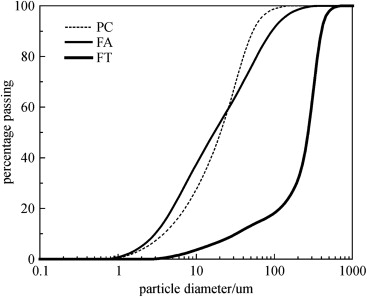
The properties of cement and fly ash used in the current study are presented in Table 1 . The corresponding size distribution is shown in Fig. 8 .
| Oxides | Portland cement (%) | Fly ash (%) | Fine tailings (%) |
|---|---|---|---|
| CaO | 64.8 | 6.09 | 11.75 |
| SiO2 | 21 | 49.96 | 46.66 |
| Al2 O3 | 6.16 | 34.02 | 17.02 |
| Fe2 O3 | 4.01 | 4.52 | 7.11 |
| Na2 O | 0.1 | 0.66 | 5.15 |
| K2 O | 0.4 | 0.98 | 1.19 |
| MgO | 1.94 | 1.17 | 3.81 |
| SO3 | 1 | 0.62 | 1.03 |
| Blaine surface area (m2 kg−1 ) | 350 | 360 | 32 |
| Relative density | 3.15 | 2.4 | 2.7 |
|
|
|
Figure 8. Particle size distribution of the raw materials. |
The mixed proportion of foam concrete, summarized in Table 2 , was calculated using the solid-volume approach (Jones and McCarthy, 2005 ). A total of 14 mixtures were prepared, as shown in Table 2 . The water-to-solid ratio refers to the weight ratio. Fly ash and fine tailings were used as fine aggregates to replace cement, with replacement percentages of 20%, 40%, and 60%, respectively. The first two mixtures contained only cement. Mixtures, numbering from 3 to 8, contained fly ash, and those numbering from 9 to 14 contained fine tailings.
| Mixture no. | Target density (kg m−3 ) | Replacement (%) | Water-to-solid ratio | Composition of mixture (per m3 ) | ||||
|---|---|---|---|---|---|---|---|---|
| PC (kg) | Aggregates (kg) | Water (kg) | Foam (L) | SP (kg) | ||||
| 1 | 500 | 0 | 0.3 | 385 | – | 115 | 761 | 3.85 |
| 2 | 1000 | 0 | 0.3 | 769 | – | 231 | 521 | 7.7 |
| 3/9 | 500 | 20 | 0.3 | 308 | 77 | 115 | 754/759 | 3.85 |
| 4/10 | 500 | 40 | 0.3 | 231 | 154 | 115 | 746/748 | 3.85 |
| 5/11 | 500 | 60 | 0.3 | 154 | 231 | 115 | 739/743 | 3.85 |
| 6/12 | 1000 | 20 | 0.3 | 615 | 154 | 231 | 507/511 | 7.7 |
| 7/13 | 1000 | 40 | 0.3 | 461 | 308 | 231 | 492/496 | 7.7 |
| 8/14 | 1000 | 60 | 0.3 | 308 | 461 | 231 | 478/483 | 7.7 |
Following the composition in Table 2 , the Portland cement and fine aggregates were dry-mixed for one minute in a vertical mixer. The total quantity of water was then added, together with the superplasticizer, and mixed with the dry batch until a homogeneous mortar without lumps of undispersed cement was obtained. Foam was then produced using a foam generator, and the approximate quantity calculated from the mixed proportions was added into the mixture. The mixture was set for at least two minutes until all the foam was uniformly distributed into the mortar. The plastic density of the final product was measured, and a ±50 kg/m3 offset from the targeted density was deemed acceptable. If the density was too high, additional foam was added incrementally until the target value was reached. The mixtures with a density below the lower bound of the acceptable range were rejected.
2.3. Testing of foam concrete
The consistency of the mixture after adding foam was determined by measuring the slump flow using a standard slump flow cone. After filling the cone with the mixture, the cone was lifted and the average flow of the foam concrete was measured without raising or dropping the flow table to prevent bubble separation from the mixture.
The compressive strength was measured in accordance with ASTM C495 on 100 mm cube specimens with 7, 28, and 90 day of curing. The strength recorded was the average of the three cubes, ensuring that the difference between the average and the individual values was less than 10%.
Specimen preparation and measurement of thermal conductivity were carried out in accordance with ASTM C177-Standard Test Method for Steady-State Heat Flux Measurements and Thermal Transmission Properties by Means of the Guarded Hot-Plate Apparatus.
2.4. Climate chamber test of the thermally upgraded wall system
2.4.1. Test setup
To investigate the effectiveness of adding foam concrete into the voids to improve the thermal performance of the hollow wall construction, two test wall panels were built in a large-scale climate chamber. This climate chamber is capable of dynamically simulating temperature, relative humidity, solar infrared radiation, solar ultraviolet radiation, and acid rain (Shi, 2010 ). For the present study, static weather profile was imposed to test the thermal resistance of the wall panels.
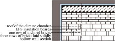
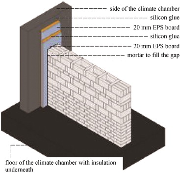
The two test wall panels were constructed with cementitious bricks described above. The panel is approximately 2.95 m high and 1.78 m wide. The climate chamber is large enough to install two panels and test them simultaneously. Fig. 9 is a 3D view of the test wall panel, illustrating the construction of the hollow wall. The bottom eight rows of bricks were laid tightly to form a section of solid wall as the base of the panel. The section above it was constructed using a hollow wall technique, with one row of strengthening bricks for every three rows of hollow walls. This configuration reflects the practice of building hollow walls in Hui-zhou. A row of bricks was laid inclined to fill the gap between the top of the wall and the roof of the climate chamber, as shown in Fig. 10 . To ensure that the heat flow is primarily through and perpendicular to the wall panel, expanded polystyrene boards were inserted to insulate the two test wall panels from each other and the climate chamber. Fig. 11 shows the insulation between the side of the wall panel and the side of the climate chamber. The insulation between the two test wall panels and between the top of the test wall panel and the bottom of the climate chamber roof was installed in a similar way.
|
|
|
Figure 9. A 3D view of the test wall panel. |
|
|
|
Figure 10. Top of the test wall panel and the inclined row of bricks to fill the gap. |
|
|
|
Figure 11. Insulation strategy to ensure a through-wall heat flow. |
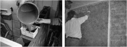
By applying different thermal upgrading strategies, four panels were actually tested. Test panel 1 was the hollow wall construction without any thermal upgrading. Thus, it was used as the benchmark. Test panel 2 was the hollow wall with the voids filled with foam concrete. Test panel 3 was the hollow wall with a 20 mm thick commercially available inorganic stucco system applied to the room side of the panel. Test panel 4 used a double upgrading strategy (i.e., with both foam concrete filling the voids and inorganic stucco system applied). Fig. 12 shows a photo of the pouring of foam concrete into the voids of the test wall panel, and another depicts the application of inorganic stucco system.
|
|
|
Figure 12. Pouring of foam concrete into the voids of the test wall panel, and the application of inorganic stucco system. |
2.4.2. Instrumentation
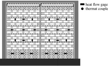
Two physical parameters, namely, heat flow and temperature, were measured to explore the thermal performance of the test wall panels. Heat flow was measured using heat flow gauges with a voltage output, and temperature was measured using thermal couples. Each wall panel has 12 measuring points, with both heat flow and temperature measured. Temperature was measured on both room and climate side surfaces so that the temperature differential can be obtained. Fig. 13 shows the positions of sensors on the room side surface of the test wall panel. Note that 12 thermal couples were installed at the same measuring points on the climate side surface of the panel, whereas the heat flow gauges were installed on the room side surface only.
|
|
|
Figure 13. Sensor configuration on the room side surface of the test wall panels. |
As shown in Fig. 13 , the sensors were installed at different positions on the wall. Three sensors were positioned at the bottom eight rows of solidly laid bricks; four sensors were positioned at the diaphragm bricks in the hollow wall section; and the other five sensors were positioned, in a cross pattern, at the face bricks in the hollow wall section. The thermal characteristics of different wall sections could be analyzed by installing the sensors in this way. Eq. (2) was used to calculate the thermal resistance of the wall at each sensor position
|
|
( 2) |
where Ri represents the thermal resistance of the test wall at the i th sensor position; tri represents the temperature on the room side surface of the wall at the i th sensor position; tci represents the temperature on the climate side surface of the wall at the i th sensor position; and qi represents the heat flow at the i th sensor position. The overall thermal resistance of the test wall panel is the arithmetic average of the 12 thermal resistances calculated using Eq. (2) .
3. Results and analysis
3.1. Foam concrete
3.1.1. Consistency
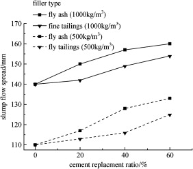
To examine the flow behavior, the slump flow spread of the mixtures after adding foam was compared, as shown in Fig. 14 . The following findings are notable:
- The slump flow increased sharply as the density increased from 500 to 1000 kg/m3 .
- For a given density, the slump flow increased as the cement replacement ratio increased. This result is particularly true for the mixtures with fly ash. A possible reason is that at lower densities, more foam leads to a reduced self-weight, and the adhesion between the bubbles and the solid particles increases, causing a higher stiffness of the paste. For a given density, the slump flow of the mixture with fly ash, compared with that with fine tailings, is relatively higher because it contains a smaller volume of foam due to its lower specific weight. In addition, the so-called “ball-bearing” effect of the fly ash particles (Fig. 15 ), which is caused by the spherical morphology of the paste, is a likely contributing factor to the increased consistency from the mixture with fly ash to that with fine tailing (Agulló et al., 1999 ). The improved packing of the solid phase and absorption of water mixed with the fly ash particles can reduce the interparticle friction (Giannakou and Jones, 2002 ). Furthermore, an increase in the amount of water mixed will reduce the yield stress of the concrete (Marrs and Bartos, 1996 ) and consequently improve spread.
|
|
|
Figure 15. Scanning electron microscopic image of the ball-bearing effect of FA particles. |
|
|
|
Figure 14. Effect of cement replacement ratio and filler type on slump flow spread. |
3.1.2. Compressive strength
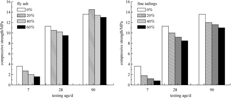
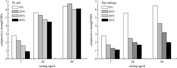
The compressive strengths of foam concrete with densities of 1000 and 500 kg/m3 are shown in Figure 16 ; Figure 17 , respectively. The graph on the left side of each figure is for the foam concrete with fly ash, and the graph on the right side is for the foam concrete with fine tailings. Fig. 16 indicates that the compressive strength of the foam concrete increases significantly from 7-day to 28-day curing. Further curing, from 28 day to 90 day, shows no significant gain in the compressive strength (She et al., 2010 ). For example, the compressive strengths of 1000 kg/m3 mixtures with 20% fly ash are 2.7, 10.5, and 14.4 MPa at the age of 7, 28, and 90 day, respectively. There is a 7.8 MPa strength gain from 7-day to 28-day curing, whereas there is only a 3.9 MPa gain from 28-day to 90-day curing. Thus, 28-day curing is deemed sufficient to achieve most of the ultimate strength.
|
|
|
Figure 16. Compressive strength of the foam concrete with a density of 1000 kg/m3 . |
|
|
|
Figure 17. Compressive strength of the foam concrete with a density of 500 kg/m3 . |
The type of fine aggregates used (fly ash or fine tailings) seems to have similar effects on the strength of the foam concrete. At the same replacement ratio, the compressive strength of the mixture containing fly ash is higher than that containing fine tailings. This result is caused by the microaggregate effect (Wang et al., 2004 ) and pozzolanic reaction of fine fly ash. The small and spherical fly ash particles fill the microvoids and increase the density. In addition, it should be noted that the fly ash used in the present study has a high fraction of reactive oxides (Al2 O3 +SiO2 +Fe2 O3 =88.5%), which means that its reactivity increases with further curing. Furthermore, the fly ash particles with a smaller size, a larger surface area, and a higher glassy phase content improve the pozzolanic reaction (Naik and Ramme, 1994 ).
Fig. 17 shows that after 90 day, the compressive strengths of 500 kg/m3 mixtures with fly ash vary from 6 to 6.7 MPa, indicating a similar trend in long-term strength gain to that observed in Fig. 16 for the 1000 kg/m3 mixture. Interestingly, unlike the 1000 kg/m3 mixture, the compressive strength of the 500 kg/m3 mixtures containing fine tailings is significantly lower than those containing fly ash. The contribution to the long-term strength gain of fine tailings seems to be reduced at a lower density. A similar behavior was observed when fly ash was replaced by unclassified fly ash (Kearsley and Wainwright, 2001 ).
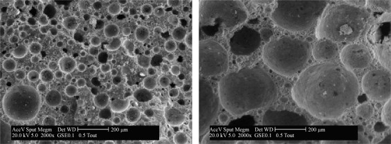
A comparison of Figure 16 ; Figure 17 indicates that the compressive strength of foam concrete decreases sharply with the decrease in density. The reason is explained in Fig. 18 : by increasing the volume of the foam and decreasing its density, the porosity and average diameter of the air voids increase, causing the compressive strength to drop. Furthermore, the quantity of irregularly formed pores increases considerably. The smaller the diameter of the pores, the more regularly they are formed. Higher porosity, larger pore sizes, and a more irregular pore structure all contribute to the decrease in the compressive strength.
|
|
|
Figure 18. Microstructure of two foam concrete mixtures with 40% FA. 1000 kg/m3 Mixture (left) and 500 kg/m3 mixture (right). |
3.1.3. Thermal conductivity
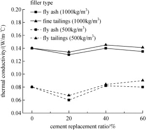
Foam concrete, compared with many inorganic materials, has a relatively low thermal conductivity due to its cellular microstructure. The thermal conductivities of foam concrete with different fillers and cement replacement ratios are compared in Fig. 19 . The following results are notable:
- Thermal conductivity decreases sharply with the decrease in density. For example, thermal conductivity varies from 0.13 to 0.145 W/m2 K when the density is 1000 kg/m3 . At 500 kg/m3 density, the range is from 0.06 to 0.09 W/m2 K. For comparison, the thermal conductivity of normal concrete is 1.70 W/m2 K, which is 12 to 28 times that of the foam concrete prepared in the current study. Therefore, reducing the density of foam concrete is an effective way to lower its thermal conductivity and to make it a better insulation material.
- The thermal conductivity of the mixtures containing fly ash is slightly lower than that containing fine tailings. This is probably caused by the smaller size of the particles in fly ash, resulting in a greater interface area, which is known to provide a more effective thermal barrier (Xu and Chung, 2000 ).
|
|
|
Figure 19. Effect of cement replacement ratio and filler type on the thermal conductivity of foam concrete. |
3.1.4. Overall thermal resistance of the test wall panels
The overall thermal resistances of the four test panels are summarized in Table 3 . Interior and exterior surface films are assumed to have a thermal conductance of 8.3 and 17 W/K m2 , respectively (Straube and Burnett, 2005 ). The values of the corresponding thermal resistance are 0.12 and 0.059 K m2 /W, respectively.
| Test panel (K m2 /W) | 1 | 2 | 3 | 4 |
|---|---|---|---|---|
| Overall thermal resistance without surface films | 0.291 | 0.403 | 0.443 | 0.581 |
| Overall thermal resistance with surface films | 0.47 | 0.582 | 0.622 | 0.76 |
Table 1 shows that by filling the voids in the hollow wall panel with foam concrete, the overall thermal resistance increased from 0.47 to 0.582 K m2 /W (a 24% increase). The overall thermal resistance of test panel 2 (hollow wall filled with foam concrete) is a little lower than that of test panel 3 (hollow wall with commercial insulating stucco continuously applied on the interior). In fact, it is only 6% less, suggesting that filling the voids with foam concrete is an effective means to thermally upgrade the wall performance. Apparently, the method of filling the voids with foam concrete and applying a continuous layer of the commercial insulating stucco offers the best thermal performance, as indicated by an overall thermal resistance of 0.76 K m2 /W found on test panel 4. This thermal resistance is even higher than 0.67 K m2 /W, which the code requires in the hot summer/cold winter climate zone. However, better thermal performance comes with a price, that is, the cost of the double upgrading strategy is, unsurprisingly, the highest among all four test panels.
4. Conclusion
The Hui-style vernacular dwelling is an important architectural heritage of China. The hollow wall construction technique is widely used to build its exterior wall systems. The thermal performance of the hollow wall is unsatisfactory, to say the least. Therefore, an appropriate strategy needs to be developed to improve its thermal performance. One key factor in selecting the appropriate thermal upgrading strategy is to ensure that the culturally important architectural features of the Hui-style wall system are maintained. Therefore, filling the voids inside the hollow wall with insulating materials is an effective means because it offers several advantages. Foam concrete is an inorganic cementitious material that offers a reasonably good thermal performance. Industrial wastes can be mixed with foam concrete to make it an environment-friendly material. Different types of foam concrete were prepared and tested in the present study. Testing results suggest that the material properties of foam concrete are suitable for thermally upgrading the hollow wall system. Two test wall panels, with four different thermal upgrading strategies, were constructed and tested. Testing results indicate that filling the voids with foam concrete can effectively improve the overall thermal resistance of the hollow wall system by 24%, which is almost equal to the overall thermal resistance when using the more expensive commercial inorganic stucco system.
Acknowledgements
This study is supported by the Ministry of Science and Technology of China (Project number 2006BAJ04A10 ) and the Research Innovation Program for College Graduates of Jiangsu Province , China (No. CXLX-0105 ).
References
- Agulló et al., 1999 L. Agulló, B. Toralles-Carbonari, R. Gettu, A. Aguado; Fluidity of cement pastes with mineral admixtures and superplasticizer—a study based on the Marsh cone test; Materials and Structures, 32 (7) (1999), pp. 479–485
- Giannakou and Jones, 2002 Giannakou, A., Jones, R., 2002. Potential of foamed concrete to enhance the thermal performance of low-rise dwellings. Innovations and developments in concrete materials and construction. In: Proceedings of the International Congress on Challenges of Concrete Construction. University of Dundee, Scotland. Thomas Telford, London, pp. 33–44.
- Jones and McCarthy, 2005 M.R. Jones, A. McCarthy; Utilising unprocessed low-lime coal fly ash in foamed concrete; Fuel, 84 (11) (2005), pp. 1398–1409
- Kan and Demirboga, 2009 A. Kan, R. Demirboga; A novel material for lightweight concrete production; Cement and Concrete Composites, 31 (7) (2009), pp. 489–495
- Kearsley and Wainwright, 2001 E.P. Kearsley, P.J. Wainwright; The effect of high fly ash content on the compressive strength of foamed concrete; Cement and Concrete Research, 31 (1) (2001), pp. 105–112
- Knapp, 1992 Knapp, R., 1992. Chinese Landscapes: The Village as Place. University of Hawaii Press, Hawaii.
- Lin et al., 2004 B.R. Lin, G.G. Tan, P. Wang, L. Song, Y.X. Zhu, G.K. Zhai; Study on the thermal performance of the Chinese traditional vernacular dwellings in summer; Energy and Building, 36 (1) (2004), pp. 73–79
- Lu, 2004 Lu, Y.D., 2004. Chinese Vernacular Housing Architecture. South China University of Technology Press, Guangzhou (in Chinese).
- Marrs and Bartos, 1996 Marrs, L., Bartos, M., 1996. Development and testing of self-compacting low strength slurries for SIFCON. In: Proceedings of the International RILEM Conference—Production Methods and Workability of Concrete. E and FN Spoon, London, pp. 199–208.
- Ministry of Construction, 2001 Ministry of Construction, 2001. JGJ 134: Design Standard for Energy Efficiency of Residential Buildings in Hot-Summer–Cold-Winter Zone. Beijing (in Chinese).
- Naik and Ramme, 1994 Naik, T.R., Ramme, B.W., 1994. Low-Strength Concrete and Controlled Low-Strength Material (CLSM) Produced with Class F Fly Ash. Controlled Low-Strength Materials. ACI SP-150. American Concrete Institute, pp. 1–13.
- Panyakapo and Panyakapo, 2008 P. Panyakapo, M. Panyakapo; Reuse of thermosetting plastic waste for lightweight concrete; Waste Management (New York, N.Y.), 28 (9) (2008), pp. 1581–1588
- Ramamurthy et al., 2009 K. Ramamurthy, E.K. Kunhanandan Nambiar, G. Indu Siva Ranjani; A classification of studies on properties of foam concrete; Cement and Concrete Composites, 31 (6) (2009), pp. 388–396 http://doi.org/10.1016/j.cemconcomp.2009.04.006
- She et al., 2010 She, W., Zhang, Y.S., Chen, W., 2010. Utilizing fly ash and fine tailing in foamed insulation materials of building. In: Proceedings of Building Environment—Science and Technology. Southeast University Press, Nanjing, pp. 496–501.
- Shi, 2010 X. Shi; Energy and long-term hygrothermal performance of building enclosures based on dynamic environmental simulation test; Engineering Sciences, 8 (1) (2010), pp. 92–95
- Steinhardt, 1990 N.S. Steinhardt; Chinese Imperial City Planning, University of Hawaii Press, Hawaii (1990)
- Straube and Burnett, 2005 J. Straube, F. Burnett; Building Science for Building Enclosures, Building Science Press Inc, Westford, Massachusetts, US (2005)
- Wang et al., 2004 A.Q. Wang, C.Z. Zhang, W. Sun; Fly ash effects: III. The microaggregate effect of fly ash; Cement and Concrete Research, 34 (11) (2004), pp. 2061–2066
- Xu and Chung, 2000 Y. Xu, D. Chung; Effect of sand addition on the specific heat and thermal conductivity of cement; Cement and Concrete Research, 30 (1) (2000), pp. 59–61
Document information
Published on 12/05/17
Submitted on 12/05/17
Licence: Other
Share this document
claim authorship
Are you one of the authors of this document?
