Abstract
We propose a Lagrangian fluid formulation particularly suitable for fluid–structure interaction (FSI) simulation involving free-surface flows and light-weight structures. The technique combines the features of fractional step and quasi-incompressible approaches. The fractional momentum equation is modified so as to include an approximation for the current-step pressure using the assumption of quasi-incompressibility. The volumetric term in the tangent matrix is approximated allowing for the element-wise pressure condensation in the prediction step. The modified fractional momentum equation can be readily coupled with a structural code in a partitioned or monolithic fashion. The use of the quasi-incompressible prediction ensures convergent fluid–structure solution even for challenging cases when the densities of the fluid and the structure are similar. Once the prediction was obtained, the pressure Poisson equation and momentum correction equation are solved leading to a truly incompressible solution in the fluid domain except for the boundary where essential pressure boundary condition is prescribed. The paper concludes with two benchmark cases, highlighting the advantages of the method and comparing it with similar approaches proposed formerly.
Keywords
Fluid–structure interaction ; Free surface flows ; Lagrangian ; Quasi-incompressible ; Added mass
1. Introduction
Fluid–structure interaction (FSI) problems involving incompressible fluid flows and flexible structures are found in many civil and mechanical engineering applications. Active research has been carried out in the field of FSI over past two decades and multiple numerical models were developed (a review can be found, e.g. in [1] ). For the problems involving light-weight structures interacting with free-surface flows quasi-incompressible Lagrangian fluid formulations coupled to the standard structural formulations proved to be very advantageous. The evolution of the free-surfaces and FSI interfaces could be tracked since it was naturally defined by the position of the moving Lagrangian mesh. On the other hand, quasi-incompressible formulations circumvent the added mass effect [2] typically encountered when standard truly incompressible fluid formulations were used [3] . This benefit was achieved due to the relaxation of the incompressibility constraint introduced by the assumption of slight compressibility. Quasi-incompressible fluid formulations have been widely used for FSI simulation both in the finite element method (FEM) [4] ; [5] ; [6] ; [7] and the smooth particle hydrodynamics (SPH) contexts [8] ; [9] ; [10] ; [11] .
For designing monolithic FSI solvers (i.e. the ones that rely on the solution of the coupled problem using a single discrete system) quasi-incompressible formulations are particularly benefitial as they allow for pressure condensation in the fluid domain while maintaining the velocity/pressure coupling. This results in (a) better monolithic system conditioning due to elimination of the different variables scales (b) simplicity of coupling with the structure when both sub-domains are described using the same primary variable (displacement or velocity). In such case elements of the fluid and the structure simply share the same degrees of freedom at a contact node. Thus, a fluid–structure problem can be solved very similarly to a single-material one. Of course, in such approaches the use of fitting interface meshes is obligatory.
Under the assumption of quasi-incompressibility the pressure is related to the kinematic field (velocity or displacement) via a constitutive equation involving the compressibility constant, also called the bulk modulus . For high values of the bulk modulus quasi-incompressible formulations provide an acceptable approximation of the incompressible behavior. The bulk modulus must be sufficiently high to conserve mass in a satisfactory way and introduce the sound propagation speed at least 1 order of magnitude higher than the expected velocity of the bulk flow. For FSI problems the one can update the fluid pressure in the coupling step using the constitutive relation ensuring that the pressure accounts for the motion of the structure. As we shall see further, this pressure update does not involve linear system solution and is therefore computationally cheap.
Quasi-incompressible fluid formulation based on linear velocity-constant pressure finite elements was proposed in [4] . Element-wise constant pressure formulation facilitated pressure condensation at an elemental level, i.e. prior to assembly. This facilitated solving the entire fluid–solid problem using a unified approach with the velocity being the only primary variable. However, the drawback of the formulation was the volumetric locking phenomenon (well-known in constant-pressure elements) that manifested already at moderately high values of the bulk modulus. On the other hand, low values of bulk modulus led to poor approximations of the incompressible behavior. In [6] ; [12] an alternative based on linear pressure interpolations was proposed. The formulation exhibited superior behavior in terms of volumetric locking. Nonetheless, the computational cost of the solver increased due to the impossibility of condensing pressure elementally when using linear pressure approximation. The global pressure condensation procedure had to be introduced. Moreover, when approaching incompressibility limit the pressure instability problems (inf-sup instability [13] ) due to using equal order velocity-pressure interpolations manifested. In general, the ambiguity of the quasi-incompressible or penalty approaches can be expressed as follows: the compressibility constant must be large enough to approximate the incompressibility accurately, but at the same time it must be small enough not to lead to “stiff” governing systems. An improvement with respect to modeling the incompressible behavior can be found in [14] , where an idea of combining the above-mentioned quasi-incompressible approaches with the fractional step strategy was proposed. The method consisted in using the momentum equation of a quasi-incompressible fluid as a prediction (fractional momentum equation). The subsequent solution of the pressure Poissons equation and the momentum equation correction led to the truly incompressible solution. The method allowed for using relatively low values of bulk modulus in the quasi-incompressible momentum equation, since the truly incompressible solution was recovered at the correction step. The necessity of the computationally expensive global pressure condensation inherited from [6] due to the use of linear pressure interpolations defined the main drawback of the methodology.
In the present work we propose one further improvement of the methods’ family developed in [4] ; [6] ; [14] . Following the idea of combining the quasi-incompressible prediction with the fractional step method, we propose to use the approximation of the volumetric term in the tangent matrix that allows for computationally efficient elemental pressure condensation, defining a major advantage in comparison with [14] . We also introduce the fluid–structure interaction coupling strategy where the modified fractional momentum equation is solved together with the momentum equation of the structure monolithically, while the subsequent “incompressible correction” steps are carried out in the fluid domain exclusively.
The paper is organized as follows. We first introduce the modified fractional momentum equation using the quasi-incompressibility assumption. An approximate linearization of the volumetric term is introduced. Correction steps ensuring truly incompressible solution are specified next. Then the solution procedure for the FSI problems is outlined. The paper concludes with two challenging FSI benchmark examples.
2. Numerical model
2.1. Governing equations for the fluid
Let us consider a fluid domain Ω with the fixed boundary Γd . We shall consider viscous incompressible Newtonian fluids being the most common in the majority of the engineering applications. The governing system are therefore the Navier–Stokes equations equipped with the incompressibility condition. These can be written as:
|
|
( 1) |
|
|
( 2) |
where v is the velocity vector, p the pressure, t the time, g the body force, ρ the density, μ the dynamic viscosity and ϵ = (∇ v + ∇ Tv )/2 – the deviatoric strain rate.
At the fixed wall Γd , homogeneous Dirichlet boundary conditions are prescribed:
|
|
( 3) |
2.1.1. Finite element formulation
The equal order linear velocity/pressure interpolations over 3-noded triangles (2D) or 4-noded tetrahedra (3D) are used here for the space discretization of the governing equations Eqs. (1) and (2) . We assume Backward Euler time integration scheme exclusively for the sake of simplicity. All the arguments presented in the paper are valid for any implicit time integration scheme. In the implementation carried out in this work the second order Newmark–Bossak scheme is used [6] . Being standard, the space and time discretization are not discussed here (see e.g. [15] ; [16] ). Pressure stabilization term is added due to the use of the equal order velocity-pressure formulation (Algebraic Sub-Grid Scales (ASGS) stabilization [17] is implemented here). Lagrangian description of the fluid is considered.
Given and at tn , the time discrete problem consists in finding and at tn +1 as the solution of
|
|
( 4) |
|
|
( 5) |
where M , L , G and S are the mass, the Laplacian, the gradient and the stabilization matrices, respectively. and are the velocity and pressure, respectively, and is the body force vector. Subindices indicate the time step. Note the absence of the convective term due to the use of the Lagrangian kinematic framework.
The matrices and vectors are assembled from the elemental contributions defined as
|
|
( 6) |
|
|
( 7) |
|
|
( 8) |
|
|
( 9) |
|
|
( 10) |
|
|
( 11) |
N stands for the vector of standard linear FE shape functions, Ωe is the element integration domain, τ is an algorithmic stabilization coefficient defined as , where h is the element size. Note also that the discrete operators given by Eqs. (6) , (7) , (8) , (9) , (10) ; (11) correspond to the unknown current configuration Xn +1 according to updated Lagrangian approach [6] ; [18] . Thus, the system is nonlinear and must be solved in an iterative manner and the discrete operators must be updated at every nonlinear iteration.
Fractional step split. Following the basic idea of the fractional step methods [19] ; [20] ; [21] , the momentum equation is split into two parts by introducing the intermediate velocity
|
|
( 12) |
|
|
( 13) |
|
|
( 14) |
where is the above-mentioned intermediate or “fractional” velocity and is the guess of the end-of-step pressure. Eq. (12) is known as “fractional momentum” and Eq. (13) as “end-of-step momentum” equations.
The novelty of these equations in contrast to those of the standard second order fractional step approach consists in using instead of in the fractional momentum equation. This idea was originally proposed in [14] , where was computed assuming slight compressibility. This is particularly advantageous for the fluid–structure interaction problems since it implies that the fractional momentum equation becomes equivalent to the momentum equation of a quasi-incompressible fluid, that can be successfully coupled to the momentum equation of the structure according to [6] or [4] . This type of coupling is completely free of the spurious added mass effect since the fluid pressure becomes coupled to the kinematic field (velocity or displacement) of the FSI problem via the pressure constitutive equation according to the quasi-incompressibility assumption. When the classical fractional step method is applied, the fluid pressure becomes completely segregated from the kinematic field in the fluid–structure coupling step [3] .
The pressure Poissons equation is obtained by applying the incompressibility condition Eq. (14) to the end-of-step momentum equation (Eq. (13) ), leading to
|
|
( 15) |
Using the typical approximation DM−1G ≈ L , we arrive at the final system to be solved:
|
|
( 16) |
|
|
( 17) |
|
|
( 18) |
Fractional momentum equation solution and pressure prediction. The momentum Eq. (16) is nonlinear due to the dependence of the discrete operators on the unknown current configuration Xn +1 . Thus, it must be solved iteratively. For this reason, let us define the residual of the fractional momentum equation
|
|
( 19) |
According to the assumption of quasi-incompressibility the unknown current-step pressure can be computed by adding the term proportional to the divergence of velocity to the pressure of the previous step (see [6] ; [14] for details):
|
|
( 20) |
where K is the bulk modulus of the fluid. The space-discrete form of the constitutive Eq. (20) using linear velocity-pressure finite elements reads
|
|
( 21) |
where Mp is the pressure mass matrix.
In order to avoid matrix inversion for obtaining the current step pressure, the pressure mass matrix Mp will be taken in the lumped format. Multiplying Eq. (21) by the inverse of the mass matrix and performing time integration one obtains:
|
|
( 22) |
where
|
|
( 23) |
Now the unknown pressure increment is expressed in terms of the fractional velocity. Since its computation involves multiplication of assembled (global) matrices M and D , it can be called the “global pressure condensation”.
Expressing the pressure increment as a function of velocity according to Eq. (23) allows us to solve the nonlinear equation
|
|
( 24) |
(with defined by Eq. (19) ) exclusively for velocity:
|
|
( 25) |
with the subsequent velocity and pressure update: and , where “i” stands for the nonlinear iteration index at time tn +1 and H is the tangent matrix defined as
|
|
( 26) |
As the non-constant pressure term is now included in the residual, it must be accounted for in the linearization. Using Eq. (22) permits to linearize the pressure gradient term with respect to velocity, giving
|
|
( 27) |
thus leading to the following expression for the dynamic tangent:
|
|
( 28) |
However, calculation of the volumetric term in the tangent matrix is a computationally tedious procedure and is feasible only if matrix-free methods are applied [6] for avoiding global matrices’ multiplication and storing the product. Instead, we propose an approximation of this term that corresponds to a element-wise constant pressure approximation. Note that this approximation will be used exclusively in the tangent matrix maintaining linear pressure elsewhere.
Discontinuous approximation for the pressure in the tangent matrix. In case of element-wise constant pressure approximation, the pressure increment (Eq. (20) ) can be computed as:
|
|
( 29) |
where the operator B and volumetric constitutive matrix CK are defined (in 2D) as
|
|
( 30) |
|
|
( 31) |
The pressure gradient can be approximated as
|
|
( 32) |
Thus, the linearization of the pressure gradient with respect to velocity can be expressed as:
|
|
( 33) |
and the resulting tangent matrix is
|
|
( 34) |
Now the linearization of the gradient of pressure increment involves elemental matrices B and CK exclusively. Thus, using element-wise constant pressure approximation permitted to condense pressure at the elemental level minimizing the associated the computational cost.
Pressure Poissons equation and the correction step. The next step to be carried out is the correction of the pressure, i.e. obtaining the end-of-step incompressible pressure using Eq. (17) . Solution of Eq. (17) requires to impose the pressure boundary conditions due to the presence of the Laplacian L . According to the methodology presented in [14] , can be used as an essential boundary condition for the pressure necessary for solving the Poissons equation. The quality of this approximation depends exclusively on the value of the bulk modulus K used in the prediction step. Having the pressure fixed to the predicted value at the free surface (or at the interface with the structure in the FSI problems), pressure Poissons equation is solved elsewhere in the domain to give the end-of-step pressure .
This step can be thus viewed as a correction of the predicted pressure to the correct end-of-step one everywhere except for the free surface (or FSI interface), where the “slightly compressible” pressure is maintained. Consequently, the projection step is carried out according to Eq. (18) and returns the end-of-step divergence-free velocity everywhere in the domain except for the pressure boundary, where the divergence-free velocity is approximated. The implementation procedure of the modified fractional step scheme is summarized in Table 1 .
| 1. Solve the modified fractional momentum Eq. (24) using the iterative procedure according to Eq. (25) and tangent matrix defined by Eq. (34) |
|---|
| • Update pressure according to Eq. (20) and add it to the fractional momentum residual |
| • Compute the new nodal position Xn +1 and move the nodes and update discrete operators |
| • Repeat until convergence in terms of velocity is achieved |
| 2. Solve the pressure Poissons Eq. (17) , using the predicted pressure as the boundary condition |
| 3. Solve the end-of-step momentum Eq. (18) |
3. Coupling with a structure
The present approach can be incorporated into the FSI strategies proposed in our works on quasi-incompressible Lagrangian fluids [6] ; [7] . According to these approaches, a unique discretization is applied to the entire domain containing both the fluid and the structure. A single monolithic FSI system of equations is solved. Thus, the interaction becomes an intrinsic feature of the method and does not involve iterative boundary conditions’ exchange between the fluid and the structure sub-domains. The fractional momentum equation for the fluid and the momentum equation of the structure can be assembled into a single system of equations. This step completely coincides with the procedure proposed in [6] ; [7] . The coupling can be applied to any structure provided that its only nodal degree of freedom is velocity (see e.g. [4] for the velocity-based formulation for solids). Alternatively, the equations for the fluid can be rewritten in terms of displacements instead of velocity in order to facilitate the coupling with displacement-based structural formulations. This ensures the compatibility of the degrees of freedom in the nodes shared by the fluid and the solid elements.
The coupled solution involves a monolithic step where fractional momentum of the fluid and the momentum equation of the structure are solved in a single system of equations and a subsequent correction step carried out in the fluid domain exclusively. The correction step consists in solving the pressure Poissons equation and end-of-step momentum equation. It ensures that the true incompressibility in the fluid domain is fulfilled.
The solution strategy of the coupled system is summarized in Table 2 .
| 1. Start the nonlinear loop |
|---|
| • Assemble the monolithic FSI system (consisting of the modified fractional momentum for the fluid and the structural momentum equation) in a standard FE manner |
| • Solve the monolithic FSI system for the primary kinematic variable (velocity or displacement) |
| • At every nonlinear iteration update the guess for the fluid pressure using the quasi-incompressible fluids’ constitutive relation |
| • Repeat until convergence in velocity is achieved |
| 2. Prescribing the pressure to the predicted value at the FSI interface, solve the pressure Poissons equation for the end-of-step pressure in the fluid domain. |
| 3. Perform the correction of the momentum equation in the fluid domain |
| 4. Go to next time step |
4. Examples
In this section two fluid–structure interaction examples are simulated using the formulation proposed. These benchmarks are characterized by the density ratio of the fluid and the structure close to 1, which defines a challenging setting for conventional fluid–structure interaction coupling schemes.
4.1. Deformation of a rubber seal
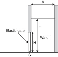
This example studies the deformation of an elastic plate subjected to water pressure. It was proposed and studied in detail in [8] ; [9] . A water container of width A = 0.1 m with water level L = 0.14 m is closed by a rubber cover of height H = 0.079 m and width s = 0.005 m, which is fixed at the top (see Fig. 1 ). The cover is released and exposed to the water column, which induces deformation. The rubber cover is modeled with the following properties: density ρ = 1100 kg/m3 , Youngs modulus E = 6 MPa and Poissons ratio ν = 0.4
|
|
|
Fig. 1. Elastic seal subjected to water pressure. |
Rubber is a nonlinear material, however in the present study linear elastic approximation is used. The value of the Youngs modulus is approximated here as 0.5(E0 + E100 ), where E0 is the Youngs modulus of the virgin material and E100 is the value that corresponds to the deformation of 100% (these values are taken from [9] ).
Water is modeled using actual properties of water. The bulk modulus value used in the prediction step was K = 10 KPa. The unstructured uniform mesh with the elemental size of 0.001 m was.
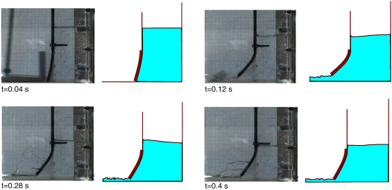
Qualitative comparison among the results of the present simulation and the experimental data published in [8] is shown in Fig. 2 . The domain configurations at t = 0.04, 0.12, 0.28 and 0.4 s are displayed. One can see a good agreement between the numerical and experimental data both in terms of the free surface of the fluid and the seal deformation.
|
|
|
Fig. 2. Elastic seal subjected to water pressure. |
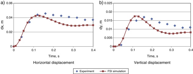
Quantitative comparison is shown in Fig. 3 . Fig. 3 a and b shows the evolution of horizontal and vertical displacements of the middle of the seal tip, respectively. One can see that the maximum horizontal and vertical displacements (around 0.042 and 0.017 m, respectively) are very close to the experimental values. Certain discrepancy is observed once the maximum deformation is obtained, which suggests that the hyper-elastic effects of the real rubber are considerable. However, in the elastic region the numerical and the experimental results match well. Overall, one can see a good agreement among the results obtained with the present simulation and the ones presented in [8] . In particular, our simulation could predict the slight “reopening” of the seal, i.e. the increment of displacements observed around 0.35 s. The difference in the maximum value is less than 10/vertical directions.
|
|
|
Fig. 3. Displacement of the rubber seal: numerical results vs. experimental data. |
4.2. Vertical elastic beam in a shallow oil sloshing
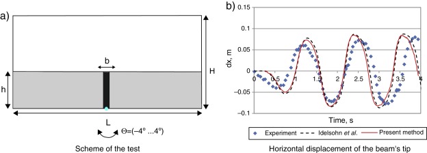
This example was studied in [5] , where experimental data and simulation results are provided. It models rotational motion of a rectangular container filled with liquid and a vertical elastic beam clamped at the bottom. The geometry of the model is shown in Fig. 4 a. The tank has a length L = 0.609 m and a height H = 0.3445 m. The real set-up has a width of 0.039 m. The container moves around a fixed point located in the mid-point of the bottom wall (x = 0.3045 m, y = 0 m). The motion with an amplitude of 4 degrees and a period of 1.21 s is prescribed to the container walls. The beam is made of polyurethane resin with the following properties: the density is 1100 kg/m3 , the Young modulus measured in a traction test amounts approximately 6 MPa. The beam has a thickness b = 0.004 m and width of 0.0332 m which is enough to simulate a 2D flow without touching the lateral walls.
|
|
|
Fig. 4. Oil sloshing in the container with an elastic beam. |
The tank was filled with sunflower oil, with the density of 917 kg/m3 and the kinematic viscosity of 5e−5 m2 /s. The original free surface level of the liquid coincided with the beam height (h = 0.1148 m). It is important to note that in the experiment, when the motor is started there is a transition from the rest state to the harmonic motion due to inertia. The numerical simulation accounted for this shift by introducing a delay of 0.25 s in the onset of the tank motion. Uniform unstructured mesh with size of 0.003 m was used.
Fig. 4 b displays the evolution of the horizontal displacement dx of the beams upper left corner. The results obtained with the present method are compared with the experimental data and the numerical simulation [5] ; [22] . One can see a good agreement with the experimental data and an almost exact match with the numerical results.
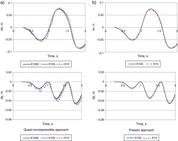
Let us examine next the benefits of the methodology proposed in the present paper in comparison with the former Lagrangian FSI formulations based on quasi-incompressibility assumption, such as [4] ; [5] or [6] . The quality of the quasi-incompressible approximations strongly depends upon the value of the bulk modulus. Fig. 5 a shows the evolution of the horizontal and vertical displacement of the elastic beam for different values of the bulk modulus K obtained using the quasi-incompressible formulation. One can see that for the value of K = 1000 KPa a perfectly smooth solution is obtained. When K = 100 Pa is used spurious oscillations appear and the solution deteriorates. For K = 10 KPa the spurious oscillations become considerably large and the fluid behavior cannot be considered incompressible anymore. These oscillations represent the compressibility effects that manifest when the bulk modulus is not large enough and the corresponding pressure waves travel with low-enough velocity to create a series of compressions–extensions in the medium.
|
|
|
Fig. 5. Vertical and horizontal displacements of the elastic beams tip in sloshing problem. |
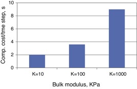
The present methodology, on the contrary, exhibits perfectly smooth solutions even for small values of the bulk modulus. Fig. 5 b shows the solutions obtained for K = 100 KPa and K = 10 KPa. One can see that the graphs practically coincide. No spurious oscillations are observed. This proves that the correction step carried out after the quasi-incompressible prediction considerably improves the solution quality in the fluid domain. Note that even in the limiting case of K = 0 one would simply recover the classical fractional step solution. However, non-zero values of bulk modulus must be used in order to ensure convergent fluid–structure interaction solution. Fig. 6 shows average computational time per time step versus bulk modulus value (the simulations were executed on Intel i7 (4 cores, 2.80 GHz) PC). One can see that for the problem at hand using K = 1000 KPa leads to computational cost practically five times higher than that of K = 10 KPa. This comparison does not pretend to represent any exact estimate of the computational benefit of the proposed method. It merely indicates the gain in the computational efficiency. It is worth noting that in 3D the improvement in the computational efficiency due to the possibility of using low bulk modulus values is even higher.
|
|
|
Fig. 6. Average computational cost per time step in sloshing simulation for different values of the bulk modulus. |
5. Summary and conclusions
This paper presented a fluid formulation that combined the features of fractional step and quasi-incompressible approaches. It consisted of the prediction for the velocity and the pressure under the assumption of quasi-incompressibility and their subsequent correction by means of pressure Poissons equation and end-of-step momentum equation. The formulation maintained the attractive features of the formerly proposed quasi-incompressible formulations for the fluid–structure interaction coupling. However, it led to truly incompressible solutions even when using low bulk modulus values in the prediction step which defines an important benefit of the proposed approach. Moreover, the proposed approximation of the volumetric term in the tangent matrix permitted elemental pressure condensation at the prediction step, defining an important improvement of our former formulation, where computationally expensive global pressure condensation was mandatory [6] .
Using the presented formulation we achieved:
- Truly incompressible solution in the fluid domain
- Possibility of using low values of bulk modulus in the prediction step
- Straight-forward and stable coupling to the structure
- Possibility of using conventional pressure stabilization techniques (in the Poissons equation)
- Computationally efficient solution strategy
- No added mass effect
The permissible time step in the proposed method is restricted by the non-negativity requirement of the elements’ Jacobian (i.e. no element can be inverted within a time step). This restriction can be possibly alleviated by using innovative streamline time integration techniques proposed in [23] . This defines one clear research line for the future.
Acknowledgement
The author of this work expresses his gratitude to the Spanish Ministerio de Economia y Competitividad for its generous support via Europa Investigacion (EUIN2015-62730 ) and FPDI-2013-18471 grants.
References
- [1] G. Hou, J. Wang, A. Layton; Numerical methods for fluid–structure interaction – a review; Commun. Comput. Phys., 12 (2) (2012), pp. 337–377
- [2] E. Van Brummelen; Added mass effects of compressible and incompressible flows in fluid–structure interaction; J. Appl. Mech., 76 (2) (2009), p. 021206
- [3] S. Idelsohn, F. Del Pin, R. Rossi, E. Oñate; Fluid–structure interaction problems with strong added-mass effect; Int. J. Numer. Methods Eng., 80 (10) (2009), pp. 1261–1294
- [4] S. Idelsohn, J. Marti, A. Limache, E. Oñate; Unified Lagrangian formulation for elastic solids and incompressible fluids. application to fluid–structure interaction problems via the PFEM; Comput. Methods Appl. Mech. Eng., 197 (2008), pp. 1762–1776
- [5] S. Idelsohn, J. Marti, A. Souto-Iglesias, E. Oñate; Interaction between an elastic structure and free-surface flows: experimental versus numerical comparisons using the PFEM; Comput. Mech., 43 (1) (2008), pp. 125–132
- [6] P. Ryzhakov, R. Rossi, S. Idelsohn, E. Oñate; A monolithic Lagrangian approach for fluid–structure interaction problems; J. Comput. Mech., 46/6 (2010) 883–399
- [7] R. Rossi, P. Ryzhakov, E. Oñate; A monolithic Fe formulation for the analysis of membranes in fluids; Spat. Struct., 24 (4) (2009), pp. 205–210
- [8] C. Antoci, M. Gallati, S. Sibilla; Numerical simulation of fluid–structure interaction by SPH; J. Comput. Struct., 85 (2007), pp. 879–890
- [9] C. Antoci, Simulazione numerica dell’interazione fluido-struttura con la tecnica SPH. Ph.D. thesis, Universita di Pavia, 2006, p. 100.
- [10] Q. Yang, V. Jones, L. McCue; Free-surface flow interactions with deformable structures using an SPH-FEM model; Ocean Eng., 55 (2012), pp. 136–147
- [11] S. Potapov, B. Maurel, A. Combescure, J. Fabis; Modeling accidental-type fluid–structure interaction problems with the SPH method; Comput. Struct., 87 (11) (2009), pp. 721–734
- [12] P. Ryzhakov, E. Oñate, R. Rossi, S.R. Idelsohn, Lagrangian FE Methods for Coupled Problems in Fluid Mechanics. CIMNE edition, 2010.
- [13] F. Brezzi, K.-J. Bathe; A discourse on the stability of the mixed finite element formulations; J. Comput. Methods Appl. Mech., 22 (1990), pp. 27–57
- [14] P. Ryzhakov, E. Oñate, R. Rossi, S. Idelsohn; Improving mass conservation in simulation of incompressible flows; Int. J. Numer. Methods Eng. (2012) (early view, published online 29/03/2012)
- [15] J. Donea, A. Huerta; Finite Element Method for Flow Problems; J. Wiley edition (2003)
- [16] R. Löhner; Applied CFD Techniques; (2nd ed.)J. Wiley and Sons edition (2008)
- [17] R. Codina; A stabilized finite element method for generalized stationary incompressible flows; Comput. Methods Appl. Mech. Eng., 190 (20-21) (2001), pp. 2681–2706
- [18] E. Oñate, S. Idelsohn, F. Del Pin, R. Aubry; The particle finite element method: an overview; Int. J. Comput. Methods, 1 (2004), pp. 267–307
- [19] A.J. Chorin; A numerical method for solving incompressible viscous problems; J. Comput. Phys., 2 (1967), pp. 12–26
- [20] R. Temam; Sur l’approximation de la solution des equations de Navier–Stokes par la methode des pase fractionaires; Arch. Ration. Mech. Anal., 32 (1969), pp. 135–153
- [21] R. Codina; Pressure stability in fractional step finite element method for incompressible flows; J. Comput. Phys., 170 (2001), pp. 112–140
- [22] J. Degroote, A. Souto-Iglesias, W. Van Paepegem, S. Annerel, P. Bruggeman, J. Vierendeels; Partitioned simulation of the interaction between an elastic structure and free surface flow; Comput. Methods Appl. Mech. Eng., 199 (33) (2010), pp. 2085–2098
- [23] S. Idelsohn, N. Nigro, J. Gimenez, R. Rossi, J. Marti; A fast and accurate method to solve the incompressible Navier–Stokes equations; Eng. Comput., 30 (2) (2013), pp. 197–222
Document information
Published on 01/03/17
Accepted on 16/09/15
Submitted on 02/09/15
Volume 33, Issue 1, 2017
DOI: 10.1016/j.rimni.2015.09.002
Licence: Other
Share this document
Keywords
claim authorship
Are you one of the authors of this document?
