Summary
Using of timber in civil engineering is increasing at the moment. Main timber elements are used for main supporting structures, typically for buildings, roofs, footbridges or towers. This work studies unique timber trusses as a supporting roof structure of spatial timber building. Timber trusses are used as roof supporting construction for objects with open inside space, especially halls or office buildings. This paper resolved critical joint in roof construction which is created by four timber trusses. The FEM model monitored strain changes in critical places of resolved joint.
Keywords
Wood ; Frame ; Timber building ; Pin joint ; FEM ; Truss
Introduction
The aim of this paper is description of heavy timber framework of administrative building and analysis of strain and fixity changes of unique spatial timber truss. This spatial truss is designed as framework for roof of atypical administrative building and it is consisted from four trusses in different axial directions. The truss in this work is design by larch wood from certain areas of Poland and Ukraine. This type of wood was used for its very good strength characteristics and for another really positive feature, its high resistance to weathering.
The critical point of the structure is the crossing of two trusses. This joint is realized without steel element, so it is realized by rods and notches. The beam and board FEM model were created to get exact strain and deformation results, which were compared.
Description of the structure
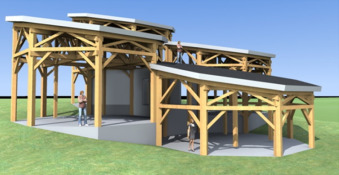
The proposed object is formed of four units, each of which has a plan shape of a regular octagon with a side length of 3.7 m; individual cells have different heights (Fig. 1 ). This paper discusses only first one. This part of building has two floors and the total height is about 8.5 m. Based on the assumption of the largest burden, this part has become the prototype for other parts of the entire building. The aim of the project was to design a building using the minimum of steel fasteners.
|
|
|
Figure 1. Set of a heavy skeleton made of four Portakabins. |
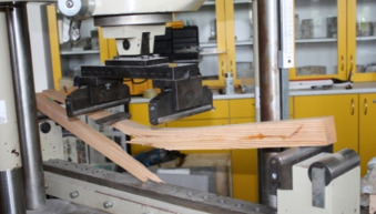
The supporting structure of the building is designed as a heavy skeleton with joints which do not use steel elements. As a building material was chosen massive larch wood of large profiles, whose origins are in different parts of Europe, particularly in Ukraine and Poland. Based on the mechanical destruction tests, the timber was placed in the C30 strength class (Fig. 2 ) (Lokaj et al., 2010 and Lokaj and Marek, 2009 ). Thanks to these strength tests it was possible to classify the wood and use it effectively in the structure.
|
|
|
Figure 2. Implementation of the strength test on wooden samples. |
Most of the construction is solved in articulated joints. The joints were designed as pin ones, using beech pegs of the D40 strength class or traditional craft joints. The construction had to be designed so that the wooden joints could transmit the resulting internal forces. The bearing capacity of the wooden dowels was based on tests conducted on the joints of historical buildings (Agel and Lokaj, 2014 ).
Because the rigidity of the timber joints is lower than steel joints, one of the most important thing, was to designed hardening system of the building.
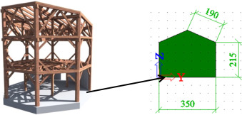
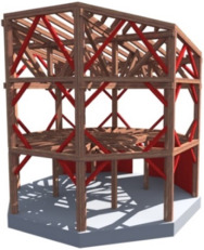
Main hardening systems of the building are the overall bracing system (Fig. 3 ) of the object, the supporting structure of the ceiling and the roof support system (Fig. 4 ). With all these design measures, there was a significant increase in the stiffness of the whole structure. The biggest influence on spatial stiffness then has a spatial truss structure. The ceiling level stiffness is ensured by a coupled wood-concrete ceiling which follows the reinforced concrete walls in the level of the first floor. Spatial stiffness is largely supported by straps placed both at ceiling level and at floor level. The straps are designed only for pressure tension.
|
|
|
Figure 3. Supporting structure of the object and ground plan of pillars. |
|
|
|
Figure 4. Designated stiffening elements. |
Truss – bearing structure of the roof
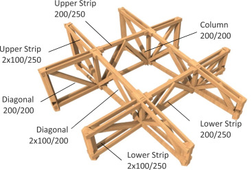
To ensure an open area without internal columns on the second floor, a roof using space truss was chosen. This design can be divided into two main directions (Fig. 3 ). In one direction are used two identical counter trusses with the upper belts slope of 12°. Pitched trusses have a structural height of 2900 mm at the highest point. Perpendicularly to these beams are placed two straight trusses of the construction heights of 1600 mm and 2300 mm. Because of the limited design lengths, the secondary elements in central fields are replaced and attached to the outer field using pin connections. The strips of the outer fields are formed by two sections so as to facilitate the installation of anchors to the support columns of the structure (Fig. 5 ).
|
|
|
Figure 5. Supporting roof construction. |
Suggestion for crossing
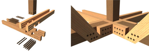
The most critical and also structurally the most interesting design detail in the structure is the crossing point of lower and upper belts trusses (Fig. 6 ). In this joint there is a crossing of elements in three directions. To achieve the same level crossing of the beam axes, these beams were given notches halfway through the profile.
|
|
|
Figure 6. Joint visualization at crossing point. |
Thanks to the intersection the node does no longer act as a hinge joint, but there are negative bending moments which can be compared to the case of restraints. Besides these bending moments there are also additional moments in the joint due to the eccentricity of the neutral axis of the notch. Such eccentricity was then affected by normal forces, which triggered parasitic bending moments. The connection was designed for axial forces, for all of the bending moments and shear force, which is transmitted in the vertical joints. All the pin connections and weakened sections were also examined. The assessment of the joints was evaluated according to the applicable CSN EN1995-1-1 standards. Within the calculation which was performed on the basis of a 3D beam joint model, the joint was designed to the use of 87% (Lokaj and Klajmonová, 2014 ).
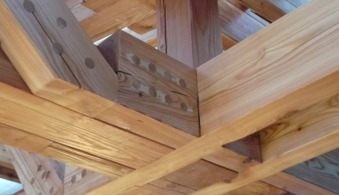
In this joint is a danger of formation of dry cracks at the place of notches (Fig. 7 ). This phenomenon significantly decreased the wood strength; particularly the pin joint strength was significantly reduced, since the pins in the holes did not physically take part in the transmission of internal forces. The negative effects of this phenomenon can be eliminated by choosing the right wood for the production of structural elements. An extreme option is then to fill in the cracks with PU based adhesive and the subsequent profile fastening (Lokaj et al., 2010 and Fojtík et al., 2015 ).
|
|
|
Figure 7. The picture of dry crack at the place of pin join. |
Experimental model of the FEM truss construction
The truss structure is structurally the most complex and demanding part of the building. To verify the correct model exposure of the finite element method the truss was first modelled as a single beam construction and then as a board structure, where the details were modelled by notches and pin connections according to the detail design. Both models were loaded by the force of 10 kN in the location of critical joints and were subsequently compared as for the significant monitored variables, the deflection and reactions (Lokaj and Marek, 2009 ).
The beam model was modelled axially using the real dimensions of structural elements. The actual position of the truss elements was taken into consideration. All joints were modelled as articulated, with the assignment of joint stiffness by calculating the kser slip module, by which the real stiffness of the joints was simulated (Fig. 8 ).
|
|
|
Figure 8. FEM beam model. |
The board model was modelled on a real parameter of the truss structure; the shape of the structural elements is modelled using wall elements on the actual thickness. In the first variant it is modelled without notches at the crossing point, in the second one then notches were already taken into account. Thanks to this measure it was possible to compare the influence of notches on stiffness of the structure. Pin connections were also realistically modelled in board models. The individual pins were attached to the wall elements with the kser rotational stiffness, calculated according to the CSN EN 1995-1-1 norm. For both board models, a net of average size pieces of 25 mm was used. In the areas of joints and the corners of notches, this net was thickened and refined to an average size of 5 mm pieces ( Figure 9 and Figure 10 ).
|
|
|
Figure 9. FEM board model with notches. |
|
|
|
Figure 10. FEM board model without notches. |
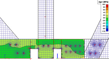
In the case of the experimental FEM plate model of the crossing, there is under the load of 10 kN per node, as shown in Fig. 11 , at the critical point reached normal compressive stress of nearly 8 Mpa, tensile normal stress is then 9 MPa, with the critical characteristic value of strength being 18 MPa. In the case of experimental load the critical notch point is used for around 50%.
|
|
|
Figure 11. Distribution of normal stress at a critical point of connection. |
Results and discussion
Both kinds of the FEM model were compared for their behaviour as for the deformation of the structure. These were mainly a vertical deflection in the middle of the margin and the maximum shift which occurred at the site of splice of the truss belts in the central field. To check the correct functioning of the particular models the intensity of reactions was observed.
The values listed in the table below show the behaviour of the structure, depending on the FEM model used. In case of using the beam model, the most favourable values are the ones of constructional deformation. It is due to the fact that the model is not considered in terms of joint geometry. Comparing the actual board models, it is obvious that the influence of the notches on the overall stiffness of the structure is not too large. The risk of notches is therefore related to the actual assessment of the tensions in the given location (Čecháková et al., 2012 ).
The stiffness of the truss was calculated as the ratio of load and deflection at the centre according to (1) . Comparing the resulting stiffness of the FEM model shows that the beam pattern is stiffest. The resulting stiffness of lattice models is evident according to Table 1 .
|
|
( 1) |
| Monitored variables | Central deflectionuz (mm) | Joints shiftuz (mm) | Stiffnessk (N m−1 ) |
|---|---|---|---|
| Beam model (Fig. 8 ) | 3.0 | 3.2 | 6 666 666 |
| Board model with notches (Fig. 9 ) | 3.9 | 4.4 | 5 128 205 |
| Board model without notches (Fig. 10 ) | 3.8 | 4.4 | 5 263 158 |
The rotational stiffness of the particular joints and pins was given by the kser module slip (2) . The pin-slip module was calculated according to the applicable European standards of CSN EN 1995-1-1 and it differed according to the sections of the pins. The FEM beam model was also assigned particular stiffness depending on the number of mechanical fasteners at the joints (Agel and Lokaj, 2014 ).
|
|
( 2) |
Conclusion
Wood as a material for building main structures is again more popular. Timber got this popularity thanks to its strength characteristics, renewability, energy use, insulation properties, and its positive effect on the human psyche. The timber is more and more used as a construction material of new types of structures. This work represent structure is one of them.
In this work there is comparing of results from rod model and board model. In both models the stiffness of the joint, calculated according to the CSN EN 1995-1-1 norm, was taken into account. Board FEM model was created to get more accurate strain and deformation results. Creating the plate model led to taking into account the geometry of dowel joints, the rotational stiffness of pins and notches, thus reducing the stiffness of the truss and increasing deformation, comparing with beam model.
In practical designing of main structures of building is beam FEM model better than more complicated board models. Creating of an accurate FEM models is useful for new types of construction systems or critical joints. For these critical structures is important to know all critical factors affecting the stiffness of the structure.
Conflict of interest
The authors declare that there is no conflict of interest.
Acknowledgement
The project was supported by the Student Grant Competition VSB – TUO . The project registration number is SP2015/185.
References
- Agel and Lokaj, 2014 P. Agel, A. Lokaj; Semi-rigid joint of timber-concrete composite beams with steel plates and convex nails; Wood Res., 59 (3) (2014), pp. 491–498 ISSN: 13364561
- Čecháková et al., 2012 V. Čecháková, M. Rosmanit, R. Fojtík; FEM modeling and experimental tests of timber bridge structure; Procedia Eng., 79–84 (2012), pp. 1877–7058 http://dx.doi.org/10.1016/j.proeng.2012.07.059
- Fojtík et al., 2015 R. Fojtík, A. Lokaj, D. Mareček; Diagnostics of footbridge over the Jizera river in Benešov; Appl. Mech. Mater. (2015) ISSN: 1660-9336
- Lokaj and Klajmonová, 2014 A. Lokaj, K. Klajmonová; Round timber bolted joints exposed to static and dynamic loading; Wood Res., 59 (3) (2014), pp. 439–448
- Lokaj and Marek, 2009 A. Lokaj, P. Marek; Simulation-based reliability assessment of timber structures; Proceedings of the 12th International Conference on Civil, Structural and Environmental Engineering Computing (2009) http://dx.doi.org/10.4203/ccp.91.148
- Lokaj et al., 2010 A. Lokaj, J. Vičan, J. Gocál; Theoretical and experimental analysis of timber structure behavior; Build. Mater., 7 (2010)
Document information
Published on 05/10/16
Licence: Other
Share this document
claim authorship
Are you one of the authors of this document?
