Abstract
This paper presents an 8051 microcontroller-based control of ultrasound scanner prototype hardware from a host laptop MATLAB GUI. The hardware control of many instruments is carried out by microcontrollers. These microcontrollers are in turn controlled from a GUI residing in a computing machine that is connected over the USB interface. Conventionally such GUIs are developed using ‘C’ language or its variants. But MATLAB GUI is a better tool, when such GUI programs need to do huge image/video processing. However interfacing MATLAB with the microcontroller is a challenging task. Here, MATLAB interfacing through an intermediate MEX ‘C’ language program is presented. This paper outlines the MEX programming methods for achieving the smooth interfacing of microcontrollers with MATLAB GUI.
Keywords
MATLAB ; MEX program ; Microcontroller ; Ultrasound scanner ; USB ; USBXpress
1. Introduction
Microcontroller-based systems offer major advancement as an internal and external control. Microcontrollers can control majority of the internal devices in a typical circuit board. Moreover majority of the chips also have built-in interfaces that can be controlled by the microcontroller. They have USB interface through which it is interfaced with external devices such as a computer or a server [1] . A low-cost USB interface for operant research using Arduino and Visual Basic is presented in [2] . Many data acquisition systems use microcontroller and USB interface [3] . The microcontroller programming is done in traditional ‘C’ language. Microprocessors and microcontrollers provide the path for the integration of hardware and software [4] . Microcontrollers have far-reaching applications in the field of instrumentation [5] and [6] .
The application in the host computer or the server is generally written in languages like ‘C’ or its variants like C++, Visual C++, Java, etc. [7] . The microcontroller manufacturers provide interface programs in the form of windows dynamically linked libraries (DLL), which can be compiled along with the applications for interfacing with the microcontroller [8] and [9] .
For applications involving signal processing, image processing or video processing, MATLAB is a more suitable programming language [10] and [11] . The quality metrics and visual perception in ultrasound imaging under different imaging conditions using MATLAB test bench were studied in [12] . In MATLAB, there are many built-in functions and routines that enable faster rollout of the application [13] . MATLAB has a very large database of built-in algorithms for mathematical modeling, image processing, simulations and computer vision applications [14] and [15] . MATLAB has the ability to read in a wide variety of both common and domain-specific image formats.
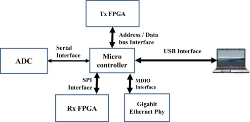
However the major challenge is in interfacing the MATLAB application with the microcontroller to get the best of both worlds. Such requirements involve live reading of images, videos, and direct processing and display [16] . One application where we came across the challenge is while developing a prototype for a medical ultrasound scanning machine [17] and [18] . The application was made in MATLAB to take advantage of the rich image and video processing capabilities [10] and [19] . The hardware has USB interfacing to the microcontroller for configuration of the various parameters of the internal chips and for performing different operations [20] , [21] and [22] . The microcontroller interfaces with different internal chips, such as ADC, transmit side FPGA (TxFPGA), receive side FPGA (RxFPGA), etc. [23] and [24] . The block schematic of microcontroller interfaces is shown in Fig. 1 . The ADC has custom serial bus programming whereas FPGAs used Serial Peripheral Interface (SPI) programming. The interface programs toward these devices were also developed for the microcontroller as well as the FPGAs.
|
|
|
Fig. 1. Block schematic of the experimental setup.
|
Neither MATLAB nor the microcontroller manufacturers provide the interface logic for interworking. Hence interworking between the MATLAB GUI and the microcontroller is a challenging task. The novel method used for interfacing using a C language interface function called MEX program is described in this paper.
2. Materials and methods
2.1. Interfacing architecture
The logical block schematic of the MATLAB GUI and microcontroller interfacing with USB is given in Fig. 2 , which indicates the microcontroller side as well as the MATLAB GUI side logic used for the study. A Silicon Laboratories C8051F340 microcontroller is used. It operates at a maximum speed of 48 MHz with 4 k of on-board RAM (XRAM) and 64 k flash memory. The microcontroller has integrated USB receiver and USB controller. It is 48 IO pins configured as 5 IO buses of 8 IOs each. The microprocessor in the ultrasound scanner prototype interfaces with a bank of ADCs and FPGAs. The microprocessor firmware is written in C language. One IO Bus is used as the programming header for programming the microcontroller. The firmware is transferred to the microcontroller using the programmer hardware by M/s Silicon Labs. The development required the USBXpress API provided by M/s Silicon Labs for including in the microcontroller firmware, firmware development, USBXpress driver installation in the host computer, installation of C++ compiler (Visual C++ used), development of the MEX file, development of the MATLAB GUI, and compilation and linking of the MEX file from MATLAB.
|
|
|
Fig. 2. Microcontroller MATLAB interface.
|
2.2. USBXpress API
The Silicon Laboratories USBXpress provides the host and device software solution for interfacing communication bridges to the USB. A high-level Application Program Interface (API) for both the host software and device firmware is used to provide USB connectivity. The USBXpress includes windows device drivers, device driver installer, host interface function library (host API) provided in the form of a DLL, and device firmware interface function library. Some of the important functions performed by the host API are given in Table 1 . While performing each function, the function returns the status of the operation like SI_SUCCESS or SI_DEVICE_NOT_FOUND or SI_INVALID_PARAMETER, along with any return values to take suitable corrective steps in read or write logics. The API is used in an interrupt driven mode. The c8051340.h and USB_API.h files supplied as part of the application are added to the project in addition to the “main” firmware file. While building the target, the USBXpress library file, USBX_F320_1.LIB is linked as an external object.
| Function name | Function |
|---|---|
| USB_Clock_Start | Initializes the USB clock |
| USB_Init | Enables the USB interface |
| Block_Write | Writes a buffer of data to the host via USB |
| Block_Read | Reads a buffer of data from the host via USB |
| USB_Int_Enable | Enables API interrupts |
| USB_Disable | Disables USB interface |
| USB_Suspend | Suspends the USB interface |
2.3. Microcontroller firmware
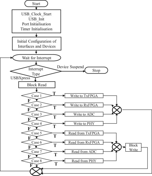
In the developed prototype, the microcontroller configures the different chips like ADC, FPGA, etc., through the control from the MATLAB GUI. Hence the microcontroller firmware implements the USB interface logic as well as the interface logic for the other devices. The header and the source files developed for the interfacing with the ADC, TxFPGA, RxFPGA and PHY device using the four IO Buses are included in the firmware. Even though the ADC side does not require any separate software logic, the FPGA side requires the hardware logic written in languages such as Verilog or VHDL. Similar interface logic is written in the FPGA side also for the read and write operations using the SPI interface. The SPI interface has read, write, chip enable, Master in Slave Out (MISO) and Master Out Slave In (MOSI) pins for the interconnection. The USB_API.h includes the definitions needed by common code to control the state of the USB peripheral, but this doesn't need to know about the specific implementation. The USB_API.h for the USB interface functions and other files like C8051F340_def.h, compiler_defs.h, stddef.h, stdio.h etc. are included in the compilation. The flowchart of the firmware is given in Fig. 3 .
|
|
|
Fig. 3. Flowchart of microcontroller firmware.
|
2.4. USBXpress DLL
M/s Silicon Labs has provided the USBXpress DLL as ‘SiUSBXp.dll’. This acts as the interface between the USBXpress driver in the host computer and the MEX file. The important functions supported by the DLL are given in Table 2 . The user initiates communication with the target USB device(s) by making a call to SI_GetNumDevices. This will return the number of target devices. This number is used when calling SI_GetProductString to build a list of device serial numbers or product description strings. To access a device, it is opened by a call to SI_Open using an index determined from the call to SI_GetNumDevices. The SI_Open function will return a handle to the device that is used in all subsequent accesses. Data I/O is performed using the SI_Write and SI_Read functions. When I/O operations are complete, the device is closed by a call to SI_Close. These functions are called for reading and writing data to the USB interface from the MEX program file.
| Function name | Function |
|---|---|
| SI_GetNumDevices | Returns the number of devices connected |
| SI_GetProductString | Returns a descriptor for a device |
| SI_Open | Opens a device and returns a handle |
| SI_Close | Cancels pending IO and closes the device |
| SI_Read | Reads a block of data from the device |
| SI_Write | Writes a block of data to the device |
| SI_SetTimeouts | Sets read and write block timeout |
| SI_CheckRXQueue | Gets the number of bytes in the device Rx Queue |
2.5. MEX interface
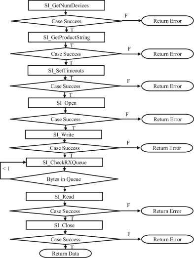
The core of the work is in the development of a MEX (MATLAB executable) file in C language whose functions are called from MATLAB. Also the MEX integrates the USBXpress DLL for connectivity with the microcontroller. Thus the MEX file acts as the interface between the MATLAB and the microcontroller. The MEX header file contains the function declarations. The MEX C++ file includes the ‘SiUSBXp.h’ file for the MEX file, which in-turn calls the functions of the ‘SiUSBXp.dll’. The flowchart of a function for reading the TxFPGA parameters is given in Fig. 4 .
|
|
|
Fig. 4. MEX function flowchart for reading a register value.
|
Similarly the other required functions are also built in the MEX file. The required Silicon Laboratories library files SiUSBXp.dll, SiUSBXp.h, SiUSBXp.lib and SiUSBXp.exp are placed in the same project folder. The MEX file is compiled into a DLL by using MATLAB linked Visual C++ compiler. The MEX file can be compiled directly from the project using the Visual C++ application also. The DLL created in this case is with name ‘USConfig.dll’. The library file ‘USConfig.lib’ containing all the function names is also placed in the same folder of the project.
The MATLAB program directly calls the MEX functions from the MATLAB file or command prompt using ‘loadlibrary’ and ‘calllib’ functions of MATLAB. These functions are suitably included as part of the MATLAB GUI code wherever required.
USBXpress comes with its own driver that needs to be installed on the host computer. Once the driver is installed, the host computer automatically recognizes the microprocessor when it is plugged in.
3. Results
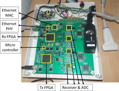
A prototype developed for the ultrasound scanner with USB interface toward the MATLAB GUI is shown in Fig. 5 . The prototype has the Silicon Laboratories C8051F340 microcontroller, Xilinx FPGAs and ADCs (AD9272) from Analog Devices. It has the microcontroller programming header as well as the USB interface. The different components above in the hardware are marked in Fig. 5 .
|
|
|
Fig. 5. Ultrasound scanner prototype hardware.
|
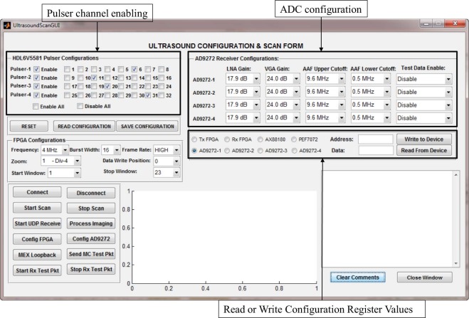
The MATLAB GUI is shown in Fig. 6 . The various ADC, FPGA, PHY, etc. configurations are performed from this GUI using the button click functions of the GUI buttons. These functions in turn call the MEX interface functions and pass the required values toward the microcontroller interface. The AD9272 configurations include the LAN Gain, VGA Gain, AAF upper and lower cutoff frequencies, enabling/disabling of different test patterns, etc. The enabling of different ultrasound channels are performed by configuring the pulsers through the TxFPGA by way of microcontroller. All these configuration parameters are coded as binary values and passed to the microcontroller. The various register values in these devices for their individual configuration are also read and written through this interface.
|
|
|
Fig. 6. MATLAB GUI for configuration of various scanner parameters.
|
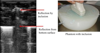
Finally the start and stop of ultrasound scan with the prototype is also controlled through the microcontrollers by configuration of the FPGAs in transmit and receive directions. For phantom testing, an Agar–Agar phantom was prepared. The ultrasound scan image is taken using a phantom with an inclusion as shown in Fig. 7 . The image is taken using a linear array transducer probe at 4 MHz. The receive beamforming, image and video processing algorithms like smoothening, sharpening, histogram equalization etc. are performed in MATLAB. The receive beamforming involved delay and sum algorithm of the simultaneously received channels. The position of the inclusion as well as the depth of the phantom is marked in Fig. 7 .
|
|
|
Fig. 7. Ultrasound image of a phantom with inclusion captured in the prototype.
|
4. Conclusion and discussion
The MATLAB interfacing with microcontroller is a major breakthrough in the design of the ultrasound machine. This enabled various signal, image and video processing requirements to be easily carried out using the MATLAB built-in functions [13] . The raw data captured were digitized and sent to MATLAB for further processing. Thus many of the hardware processing were transferred to software algorithms in MATLAB, like the beamforming, etc., in host computer, thus reducing the size and complexity of the hardware. The software processing of Doppler ultrasound system with USB-based high data rate communication is presented [21] , where the digital signal processing is shifted from hardware to software algorithms. This also helped in the development of an ultrasound machine suited for tele-medicine applications [23] .
This interfacing has larger implications in other wide areas of microcontroller control and programming, and hence is a very innovative approach. This also has many applications in areas of sensors, including medical electronics. There are large numbers of implementations of microcontroller interfacing with native ‘C’ or Java applications. However there are no such implementations available for the interfacing of the microcontroller with MATLAB.
In this application, the data received from the ultrasound transducers are captured as Ethernet packets through the Ethernet interface. As a future step, capturing the packets through the USB interface can also be implemented.
Acknowledgments
The authors thank the Department of Science and Technology, Government of India for providing financial support for this project with Grant Number SR/WOS-A/ET-24/2008 . The authors also state that the sponsor does not have any role in study design; collection, analysis and interpretation of data; writing of the report; and in the decision to submit the article for publication.
References
- [1] C.-H. Huang, M.-F. Chiu, J.-F. Chou; USB interface data transmission device and USB interface data communication system; Google patents (2012)
- [2] R. Escobar, C.A. Pérez-Herrera; Low-cost USB interface for operant research using Arduino and Visual Basic; J. Exp. Anal. Behav, 103 (2015), pp. 427–435 http://dx.doi.org/10.1002/jeab.135
- [3] A. Bora, K.C. Sarma; Design of a USB based multichannel, low cost data acquisition system using PIC microcontroller; Int. J. Comput. Appl, 59 (2012), pp. 5–8
- [4] A. Al-Dhaher; Integrating hardware and software for the development of microcontroller-based systems; Microprocess. Microsyst, 25 (2001), pp. 317–328 http://dx.doi.org/10.1016/S0141-9331(01)00124-7
- [5] V. Kaundal, A.K. Mondal, P. Sharma, K. Bansal; Tracing of shading effect on underachieving SPV cell of an SPV grid using wireless sensor network; Eng. Sci. Technol (2015) http://dx.doi.org/10.1016/j.jestch.2015.03.008
- [6] B. Mondal, M. Meetei, J. Das, C.R. Chaudhuri, H. Saha; Quantitative recognition of flammable and toxic gases with artificial neural network using metal oxide gas sensors in embedded platform; Eng. Sci. Technol, 18 (2015), pp. 229–234 http://dx.doi.org/10.1016/j.jestch.2014.12.010
- [7] D.T. Martinez, T.U. Ganiron Jr., C.S. Lacsamana; Development of hardware interfacing system for Visual C++; Int. J. Adv. Appl. Sci, 2 (2013), pp. 201–204
- [8] T. DeBoer, P. Carbone, J. Waldman, D. Johnson, R. Dautel; System and method for communicating with a microcontroller; Google patents (2013)
- [9] P.C. Pradhan, R.K. Sahu, S. Panda; Firefly algorithm optimized fuzzy PID controller for AGC of multi-area multi-source power systems with UPFC and SMES; Eng. Sci. Technol (2015) http://dx.doi.org/10.1016/j.jestch.2015.08.007
- [10] J. Ferrer-Buedo, M. Martínez-Sober, Y. Alakhdar-Mohmara, E. Soria-Olivas, J.C. Benítez-Martínez, J.M. Martínez-Martínez; Matlab-based interface for the simultaneous acquisition of force measures and Doppler ultrasound muscular images; Comput. Methods Programs Biomed, 110 (2013), pp. 76–81 http://dx.doi.org/10.1016/j.cmpb.2012.09.009
- [11] R. Gupta, J. Bera, M. Mitra; Development of an embedded system and MATLAB-based GUI for online acquisition and analysis of ECG signal; Measurement, 43 (2010), pp. 1119–1126 http://dx.doi.org/10.1016/j.measurement.2010.05.003
- [12] X. Zhao, J. Zhou, W.-F. Loke, M. Chirala, C. Zhang; Quality evaluation of ultrasound imaging using a MATLAB test-bench; SPIE Medical Imaging, International Society for Optics and Photonics (2013), p. 867516
- [13] J. Blahuta, T. Soukup, P. Čermák, D. Novák, M. Večerek; Semi-automatic ultrasound medical image recognition for diseases classification in neurology; Advances in Intelligent Analysis of Medical Data and Decision Support Systems, Springer (2013), pp. 125–133
- [14] N. Sandeep, C. Sulochana; Dual solutions for unsteady mixed convection flow of MHD micropolar fluid over a stretching/shrinking sheet with non-uniform heat source/sink; Eng. Sci. Technol, 18 (2015), pp. 738–745 http://dx.doi.org/10.1016/j.jestch.2015.05.006
- [15] S. Padmanaban, E. Kabalci, A. Iqbal, H. Abu-Rub, O. Ojo; Control strategy and hardware implementation for DC–DC boost power circuit based on proportional–integral compensator for high voltage application; Eng. Sci. Technol, 18 (2015), pp. 163–170 http://dx.doi.org/10.1016/j.jestch.2014.11.005
- [16] J.J.R. Raj, S. Rahman, S. Anand; Application of a novel software algorithm for information reduction in high frame rate ultrasonography; Int. J. Comput. Appl. Technol. Res, 3 (2014), pp. 729–733 http://dx.doi.org/10.7753/ijcatr0311.1016
- [17] J.J.R. Raj, S. Rahman, S. Anand; Acquisition of lossless data in transient window through ethernet in high frame rate machines; 2015 2nd International Conference on Computing for Sustainable Global Development (INDIACom), IEEE, New Delhi (2015), pp. 591–596
- [18] M. Tiouririne, S. Nguyen, J.A. Hossack, K. Owen, F. William Mauldin Jr.; Handheld real-time volumetric imaging of the spine: technology development; J. Med. Eng. Technol, 38 (2014), pp. 100–103 http://dx.doi.org/10.3109/03091902.2013.877989
- [19] J.J.R. Raj, S. Rahman, A. Sneh; Electronic hardware design for ultrasound transient elastography; Int. J. Eng. Sci. Technol, 4 (2012), pp. 3700–3704
- [20] D. Jones; Smartphone-compatible ultrasound probe; J. Diagn. Med. Sonogr, 30 (2014), pp. 200–204 http://dx.doi.org/10.1177/8756479314534523
- [21] B.-E. Byambasuren, M. Oyun-Erdene, S.-Y. Nam, D.-H. Kim, S.-M. Han; Design of USB-based high rate data communication for transcranial Doppler ultrasound system; Int. J. Control Autom, 5 (2012), pp. 97–106
- [22] Y.-S. Lee, J.-H. Yang, S.-Y. Kim, W.-S. Kim, O.-K. Kwon; Development of a rapid control prototyping system based on Matlab and USB DAQ boards; J. Inst. Control Robot. Syst, 18 (2012), pp. 912–920 http://dx.doi.org/10.5302/j.icros.2012.18.10.912
- [23] N. Li, J. Guo, H.S. Nie, W. Yi, H.J. Liu, H. Xu; Design of embedded bio-impedance analyzer based on digital auto balancing bridge method; Applied Mechanics and Materials, Trans Tech Publication Ltd (2012), pp. 396–401
- [24] J. Raj, S. Rahman, S. Anand; Interfacing high frame rate data through ethernet without loss for tele-medical applications; 2015 International Conference on Signal Processing and Communication (ICSC), IEEE (2015), pp. 51–55
Document information
Published on 10/04/17
Licence: Other
Share this document
Keywords
claim authorship
Are you one of the authors of this document?

