1 Introducción
In the last decades polymeric composite materials have been used worldwide in advanced markets, such as, the aeronautical, aerospace and sports [1, 2]. Their outstanding mechanical properties allied to a low density, turn them much more competitive and attractive for advanced applications than other most common traditional materials [3]. However, these materials still present some weakness when submitted to some kinds of loading, such as, impact, dynamic and flexural, due to their brittleness and layer-by-layer inherent nature [4]. Low velocity impacts (LVI) are one of the most dangerous events that composite laminate must face in their life time. These solicitations may develop imperceptible internal laminate damages, namely delaminations, that tend of propagate in service and compromise performance of composite parts [5].
Incorporation of thin veils between plies have already shown to increase interlaminar fracture toughness in Mode I and II [6, 7], however there are not yet many studies regarding how their usage may improve damage tolerance caused by impact events. Walker et al. [8] has shown that interleave short fibres of different materials on the interlaminar region of CFRP composites could a reduce the global and local damage. Hogg [9] interleaved carbon-polyester veils and observed an increment of compression after impact (CAI) of laminates. Stanley et al. [10] found out that, despite the void spots presented by interleaved laminates, the use of polyamide (PA) veils reduced damage area and increase CAI resistance. Tanoglo et al. [11], also interleaved PA veils into a CFRP laminate and has shown that those interlaminar structures improved the Charpy impact strength, however a a reduction of in plan mechanical properties have been reported. García-Rodríguez et al. [12] introduced a low melt temperature coPA between each single interlaminar region and found out that, in some cases, this allowed to increase the CAI strength and reduce low velocity impact damage area in more than 100 %.
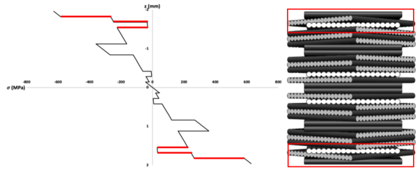
The major drawback regarding the incorporation of toughening structures between composite laminate layers is the increment of thickness and weight of the final part. To minimise this problem, in this work, a theoretical study on stresses distribution across the thickness when a standard aeronautic laminate is under a bending moment was first carried out in order to identify the six interfaces where the discrepancies between stresses are higher, finally four thin veils of different materials were placed on those interlaminar regions and their low velocity impact and interlaminar shear strength response were compared to a non-interleaved one.
2 Approach
In this work, only six plies of four different thin veil were used as interlaminar tougher of a carbon/epoxy laminate typically used in aircraft in order to improve the impact damage tolerance an avoid thickness overage,.
Based on the idea that low velocity impact events are predominantly dominated by bending and shear stresses, a theoretical study supported on the Classic Lamination Theory (CLT) was carried out in order to calculate stresses distribution across the thickness of the studied carbon/epoxide laminate. Then, the six most critical interfaces (those which have presented higher difference stresses between plies) were selected to interleave thin veils made from four different materials (glass, carbon, aramid and polyester) to try achieving better LVI damage tolerance.
3 Materials and processing
All laminates were manufactured by vacuum bag infusion with twenty-eight layers of 150 g/m2 unidirectional (UD) carbon fibre fabrics (Dynanotex HS 24/150 DLN2 provided by G. ANGELONI s.r.l., Italy), impregnated with a bi-component epoxy resin from Sika® (Biresin® CR83 resin and Biresin® CH83-6 hardener). Each of these layers had a final thickness of approx. 0.145 mm.
Four unwoven thin veils made from glass (~17 g/m2), carbon (~17 g/m2), aramid (~14 g/m2) and polyester (~17 g/m2) fibres (from ACP Composites, USA), with thicknesses of 0.127, 0.14, 0.132 and 0.119 (mm), respectively, were used as interlaminar tougher in order to improve impact damage tolerance of the standard laminate (LS) of reference. All values presented on this description are defined in the supplier’s data sheets.
Table 1 presents the different laminates produced: the LS and 4 other ones using different interleaved veils. Each one of these latter 4 laminates were manufactured using six veil interleaved plies made from just only one of the above described four material types. The behaviour of such laminates, using thin veils strategically placed between the previously selected UD carbon layers, was then compared to the standard one (LS) manufactured with the same stacking sequence but without interleaved veils. Capital letters G, C, A and P were used to designate the glass, carbon, aramid and polyester veils, respectively.
| Laminate | Stacking Sequence |
| LS | [0/45/90/-45/45/-45/0]2S |
| GL_P | [0/G/45/G/90/G/-45/45/-45/0/0/-45/45/-45/90/45/0]S |
| CL_P | [0/C/45/C/90/C/-45/45/-45/0/0/-45/45/-45/90/45/0]S |
| AL_P | [0/A/45/A/90/A/-45/45/-45/0/0/-45/45/-45/90/45/0]S |
| PL_P | [0/P/45/P/90/P/-45/45/-45/0/0/-45/45/-45/90/45/0]S |
The studied laminates, with dimensions of approx. 650 x 500 x 4 (mm), were manufactured by vacuum bag infusion at room temperature and submitted to a post-curing treatment at 70 ºC inside an oven during 8 hours. While all composite plates have presented very similar thicknesses close to 4 mm, it should be mentioned that their final thickness was always slightly affected by the type of thin veil used.
4 Experimental
4.1 Laminates characterisation
A calliper rule was used to measure the thickness of the laminates. Four measurements were made on each impact specimen and the thickness increment caused by the incorporation of veils was evaluated.
Four samples of each laminate plate were randomly picked and carefully polished for being inspected under the scanning electron microscope (SEM) in order to evaluate the process quality, void content and layer thicknesses.
4.2 Interlaminar shear strength (ILSS) tests
Interlaminar shear strength tests were performed in accordance with ISO 14130 standard. The results allow to evaluate and compare how the different interleaved veils influence the global resistance to delamination of the produced laminates. All experiments were performed at a loading speed of 1 mm/min using a 50 kN Shimadzu universal testing machine. Specimens with dimensions of 40×20 (mm), which means having approximately a length and a width, respectively, 10 and 5 times higher than its thickness, were used in the tests according standard recommendations.
The interlaminar shear strength of each specimen, , was calculated from the obtained data, as:
|
|
(1) |
where, F, b, and h are the maximum applied load and the specimen width and thickness, respectively.
4.3 Low velocity impact tests
All low velocity impact tests were performed in accordance with ASTM D7136/D7136M standard. A drop weight impact testing machine “Fractovis Plus” from Ceast using an anti-rebounding system was used with a 20 mm diameter hemispherical steel stricker, equipped with a piezoelectric accelerometer, with a total drop mass of 5.045 kg was used in the impact tests made at the energy levels of 13.5, 25 and 40 J, while a drop mass of 16.044 kg was used in the same impactor in the tests made at 80 J energy level. The different energy levels were obtained by adjusting the impactor height between the striker and specimen upper impact surface. Specimens with 150x100 (mm) were held to a support steel plate by the means of four clamps with rubber tips. This supporting plate exhibits a 125x75 (mm) hole at its centre, which by staying below the specimen allows exposing it to the impact. Three specimens of each laminate were submitted to the four different impact energy levels, although only two of LS laminate had been used in the tests at the 13.5, 25 and 40 J.
Using the load history of each test recorded by the impact equipment software and admitting a perfect contact between the impactor and the specimen, the support plate and the specimen, the specimen and clamps and by considering that kinetic energy (KE) equals the previously selected total energy test level, the initial velocity of the impactor (vi) may be calculated at moment of impact from the following equation:
|
|
(2) |
where m is the total drop mass and vi is the initial impactor velocity.
Furthermore, during the impact, the velocity of the impactor may be calculated at any time t by using the numerical integration of the force versus time stated by the equation:
|
|
(3) |
where v(t) is the impactor velocity at time t, g the gravitational acceleration and F(t) the load measured at the same instant t. Finally, the energy absorbed by the specimen at each instant, Ea(t) is determined as:
|
|
(4) |
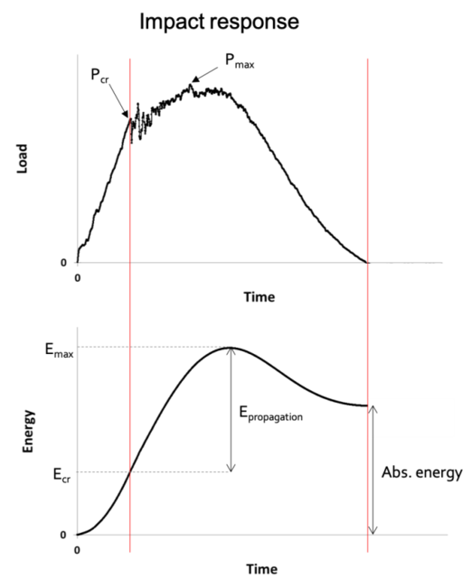
Regarding damage propagation onset, the simultaneous interpretation of contact load and absorbed energy histories obtained from the testing curves could be more explicit to assess laminates onset critical load (Pcr) and absorbed energy (Ecr). In this work these two critical values will be analysed concerning tolerance to damage propagation onset of each of the produced laminates at the four different impact energy levels.
Figure 2 depicts a typical contact load and absorbed energy history curves obtained from an impact test made on a composite specimen, where Pcr and Pmax represent the critical and maximum obtained forces, respectively, and Ecr and Emax the critical and maximum absorbed energy, respectively, are identified on them.
5 Results and discussion
5.1 Laminates characterization
Table 2 presents the average of thickness of each laminate and its increment caused by the interleaved veils.
As expected, the incorporation of veils caused an increment on thickness of the laminate. The results have shown that the laminate interleaved by carbon veils (CL_P) presented higher thickness, followed by the one using interleaved aramid veils (AL_P) and, the laminates reinforced with polyester veils (PL_P) revealed to have slightly higher those having glass fibre veils (GL_P).
| Laminate | Thickness (mm) | Thickness increment (%) | |
| Average | Std. Dev. | ||
| LS | 3.86 | 0.055 | - |
| GL_P | 4.32 | 0.031 | 12.0 |
| CL_P | 4.77 | 0.341 | 23.5 |
| AL_P | 4.55 | 0.023 | 17.7 |
| PL_P | 4.42 | 0.021 | 14.5 |
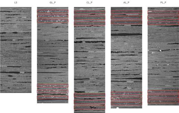
Figure 3 shows scanning electron microscopy (SEM) images that were used to evaluate the laminate structures and presence of void. Highlighted in red, it’s possible to see the interleaved veils in the figure. The dark spots on images represent the adhesive resin used by UD carbon fibre producer to bond and keep together the carbon fibres and the weft thread in the UD tissue.
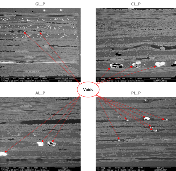
The presence of voids in the final laminates were also investigated by SEM. The observations (Figure 4) have shown that CL_P and AL_P laminates presented a higher number of voids than all the other ones and that they were typically found in the first and second laminae near the external surfaces. On the other hand, smaller void spots were typically found, mostly in the UD carbon fibre laminae of the GL_P and PL_P laminates. No void spots were found in the LS laminates.
The easy resin flow promoted by veil layers during vacuum bag infusion process, lead to higher resin concentrations than UD carbon fibre ones and this increases the laminate thickness. High permeability of veils layer may trap the air present in lower permeable environments, explaining the presence of voids between UD carbon layers. The SEM observations also suggested that, during the curing process, the epoxy resin reached a high enough exothermic peak temperature to soften (above Tg) the polyester fibres on PL_P laminate, which may have cause the change of their initial circular shape to a much irregular one.
5.2 Interlaminar shear strength (ILSS) tests
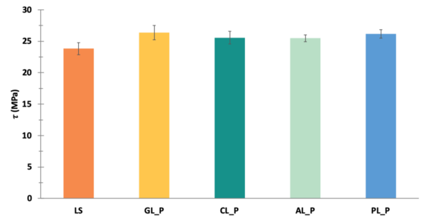
Figure 5 presents the interlaminar shear strength results obtained from the ILSS tests made on the laminates. As it may be observed, all interleaved laminates presented slightly higher global resistance to delamination than the non-interleaved one (LS). It seems that the inclusion of thin veils led to a more uniform distribution of shear stresses on the selected interfaces, redirecting the loading to the carbon fibre tissues and increasing by that way the interlaminar shear resistance.
5.3 Low velocity impact tests
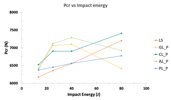
The Pcr critical load value is an important feature to analyse the damage onset. The average Pcr values obtained for each laminate from the impact tests made are depicted in Figure 6.
As it may be seen, all laminates have shown an increase on Pcr with the increment of impact energy, with the exception of GL_P and AL_P laminates, that presented lower Pcr values at 80 J than those ones observed at 25 J. Up to 40 J of impact energy level, all interleaved laminates presented higher Pcr values in comparison to the LS laminate, while at 80 J only CL_P has presented higher Pcr load than the LS one.
It’s possible to concluded that the CL_P laminate presented the better performance at 13.5 J of impact energy level. However, when the impact energy level rises until 40 J, AL_P laminate have shown better ability to bear load before damage propagation, followed by the GL_P laminate and, after, the CL_P one. The PL_P laminate demonstrated the poorest behaviour in all the three lower impact energy levels.
Finally, at 80 J impact energy level, both AL_P and GL_P presented a drastic reduction on their capability to bear load before damage propagation. On the other hand, at the same impact energy, all other laminates presented higher Pcr values than those that were obtained at 40 J. The better performance was obtained in the CL_P laminate in these conditions, which was followed by the LS, AL_P, PL_P and GL_P laminates, respectively.
Despite the higher number of voids founds, it seems that laminates interleaved with aramid veils were able to improve the resistance to damage propagation most likely due to the recognised ability of these fibres to absorb energy. In the case of GL_P laminate, it seems that the better impregnation they presented resulted in a more efficient toughening of the selected interlaminar regions, which has provided higher tolerance to damage propagation onset. The laminate interleaved with carbon fibre veils has shown to have higher values of Pcr than LS laminate at all selected impact energy levels. Despite the number of voids observed under SEM, one of the reasons for this behaviour may be explained by the larger thickness presented by the CL_P laminate relatively to the non-interleaved one. Finally, in contrast to what was expected due to the ductile nature of polyester fibres, the PL_P laminates exhibited poorest performance until the 40 J impact energy level which may be related with the large number of voids found in the SEM observations in the intra and interlaminar untoughened regions.
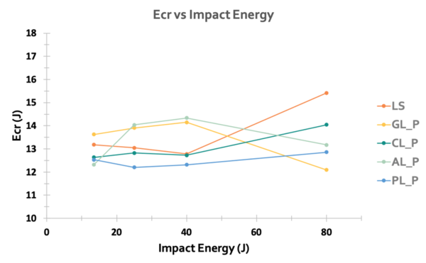
Another important factor to be studied is the ability of the laminate dissipated energy until the damage propagation onset happens, Ecr. The average of Ecr values obtained for all laminates studied in this work at the four impact energies previously defined are ploted in Figure 7.
As it may be observed on Figure 7, all laminates seemed to present an energy threshold at the damage propagation onset between 12 and 15.5 (J). At the lower impact energy level of 13.5 J, the CL_P, AL_P and PL_P laminates presented almost the same amount of Ecr, while LS and GL_P laminates have shown better capability of dissipating energy before damage propagation. When the impact energy rises to 25 and 40 (J), GL_P and AL_P laminates seem to be able to dissipate slightly higher energy without severe damage than the other ones. Under these conditions, LS and CL_P laminates have shown to be able to dissipate almost the same amount of energy. At 80 J, LS laminate presented higher values of Ecr followed be interleaved laminates, with carbon, aramid, polyester and finally glass veils. Polyester interleaved laminate presented the poorest behaviour up to the 40 J impact energy testing level, while it showed to be slightly better than GL_P laminate at 80 J.
As it was expected by the analysis of Pcr load, GL_P and AL_P laminates have shown to be able to absorb higher amount of energy before damage propagation than all the other laminates, especially for impact energies levels between the 25 and 40 (J). The main reasons for this behaviour are probably those already mentioned before and additional experimental work, as non-destructive and destructive tests, will must be carried out in order to better evaluate the main dissipation mechanisms occurred during the impact event.
6 Conclusions
In this work, a conventional aircraft laminate was strategically interleaved with six layers of four different thin veils in order to improve its tolerance to onset impact damage. All laminates were characterized and compared with respect to their thicknesses and the presence of voids after processing by vacuum bag infusion that was evaluated by using the scanning electronic microscopy (SEM) technique. Their interlaminar shear strength and tolerance to damage propagation were also investigated by low impact velocity (LVI) tests made at four impact energy levels. The evaluation of process quality by SEM has shown that when veils were interleaved between the UD carbon layers, an easy resin flow environment was created which had trap air inside UD carbon tissues causing dry spots (voids) on the laminate. Despite voids presence on interleaved laminates, the strategical inclusion of thin veils on interfaces that present the largest difference of stresses due to a bending moment, revealed to improve the overall resistance to delamination. Under low velocity impact tests, glass and aramid fibre veils interleaved laminates demonstrated slight enhancements on Pcr and Ecr when compared to non-interleaved laminate, specialty for impact energies up to 40 J.
Future work will be carried out in order to obtain a better characterization of the laminates. Tensile and three-point bending tests will be performed and the failure mode of laminates under ILSS tests will be analysed. Non-destructive and destructive tests will be also used to evaluate the damage area caused and understand the main mechanisms used during LVI tests to dissipate energy. A new strategical placement of the veils is also being studied to evaluate their influence when placed at the interfaces of higher shear tensions when laminate is under a bending moment.
Acknowledgments
The authors acknowledge the financial support of the project “IAMAT – Introduction of advanced materials technologies into new product development for the mobility industries” under the MIT-Portugal program exclusively financed by FCT- Fundação para a Ciência e Tecnologia. The authors also acknowledge PIEP (Centre for the Innovation in Polymer Engineering) for yielding of facilities and equipment.
References
[1] M. F. S. F. Moura, A. B. Morais, and A. G. Magalhães, Materiais Compósitos - Materiais, Fabrico e Comportamento Mecânico, 1 a. Porto: Publindústria, 2005.
[2] F. A. Administration, “Aviation Maintenance Technician Handbook - Airframe,” Aviat. Maint. Tech. Handb. - Airframe, vol. 1, p. 588, 2012.
[3] G. Gardiner, “Aerocomposites: The move to multifunctionality : CompositesWorld,” 2015. [Online]. Available: http://www.compositesworld.com/articles/aerocomposites-the-move-to-multifunctionality. [Accessed: 14-Jul-2017].
[4] F. Gnädinger, P. Middendorf, and B. Fox, “Interfacial shear strength studies of experimental carbon fibres, novel thermosetting polyurethane and epoxy matrices and bespoke sizing agents,” Compos. Sci. Technol., vol. 133, pp. 104–110, 2016.
[5] V. Tita, J. de Carvalho, and D. Vandepitte, “Failure analysis of low velocity impact on thin composite laminates: Experimental and numerical approaches,” Compos. Struct., vol. 83, no. 4, pp. 413–428, 2008.
[6] M. Kuwata and P. J. Hogg, “Interlaminar toughness of interleaved CFRP using non-woven veils: Part 1. Mode-I testing,” Compos. Part A Appl. Sci. Manuf., vol. 42, no. 10, pp. 1551–1559, 2011.
[7] M. Kuwata and P. J. Hogg, “Interlaminar toughness of interleaved CFRP using non-woven veils: Part 2. Mode-II testing,” Compos. Part A Appl. Sci. Manuf., vol. 42, no. 10, pp. 1560–1570, 2011.
[8] L. Walker, M. Sohn, and X. Hu, “Improving impact resistance of carbon- ® bre composites through interlaminar reinforcement,” Compos. Part A, vol. 33, pp. 893–902, 2002.
[9] P. J. Hogg, “Toughening of thermosetting composites with thermoplastic fibres,” Mater. Sci. Eng. A, vol. 412, pp. 97–103, 2005.
[10] N. H. Nash, T. M. Young, and W. F. Stanley, “An investigation of the damage tolerance of carbon / Benzoxazine composites with a thermoplastic toughening interlayer,” Compos. Struct., vol. 147, pp. 25–32, 2016.
[11] B. Beylergil, M. Tanoglo, and E. Aktas, “Effect of polyamide-6 , 6 ( PA 66 ) nonwoven veils on the mechanical performance of carbon fi ber / epoxy composites,” Compos. Struct., vol. 194, no. February, pp. 21–35, 2018.
[12] S. M. García-rodríguez, J. Costa, V. Singery, I. Boada, and J. A. Mayugo, “The effect interleaving has on thin-ply non-crimp fabric laminate impact response : X-ray tomography investigation,” Compos. Part A J., vol. 107, no. January, pp. 409–420, 2018.
Document information
Published on 01/06/22
Accepted on 01/06/22
Submitted on 28/05/22
Volume 04 - Comunicaciones Matcomp19 (2020), Issue Núm. 1 - Avances en Materiales Compuestos. Nuevos Campos de Aplicación., 2022
DOI: 10.23967/r.matcomp.2022.06.013
Licence: Other
Share this document
claim authorship
Are you one of the authors of this document?
