Abstract
Wing stiffness center should be determined firstly for structure detail design. The present study focused on the impact analysis of beam and stringer for wing cross-section stiffness center based on thin wall structure mechanics theory. In order to discuss the impact of beam and stringer on stiffness center, the sensitivity formulas for stiffness center of wing cross-section were derived and expressed in terms of the dimension and layout of beams and stringers. The results indicated that the structural layouts of beam and stringer were important influencing factors in stiffness detail design of full composite wing structure. The research results can provide an important reference for the stiffness design and aeroelastic design of the full composite wing.
Keywords: Composite wing, stiffness center, layout, dimension, sensitivity
1. Introduction
In structure detail design of aircraft, the stiffness center of the wing structure is an important factor which must be considered. Not only the aerodynamic force was impacted by stiffness center of composite wing, but also the distribution of static and the deformation of aeroelastic [1]. When the cross sections from wing root to wing tip are selected, the wing stiffness center axis can be determined by calculating stiffness center of each cross-section.
At present, many researchers focus on studying the stiffness center of the wing section. They are based on structural mechanics theory and use model simplification methods to determine the stiffness center position [2-5], which is efficient and utility in engineering design. Based on the N-S equation, Ye et al. [6] not only analyzed the airfoil flow field characteristics, but also studied the influence of different positions of the elastic axis on the aerodynamic characteristics. Cesnik et al. [7] carried out the optimization design of the internal layout of the blade structure by controlling the position of the elastic axis of the helicopter blade, and in order to maximize the static twist actuation of the blade. The effect of the elastic axis was investigated, with the elastic axis closing to the airfoil midpoint, the pitch amplitude increases slightly while the plunge amplitude fluctuates with an extremum [8].
Sensitivity is also the derivative information, which reflects the impact of design variable on objective function or constraint function [9]. As an important research field in engineering, analysis was used previously in shape optimization of continuum structures and structure response [10-11]. Later according to different design requirements, sensitivity formulas were derived individually based on shape design variations or structure parameters [12-15], structure static responses, dynamic responses [16-21], and linear or nonlinear functions [22-25]
Before starting the calculation of the wing stiffness center, the paper needs to simplify the cross-sectional structure of the wing using an equivalent method.Firstly, based on the simplified cross-sectional structure of the wing, the calculation formula of the cross-sectional stiffness center is derived by using the related theory of thin-walled structural mechanics.Secondly, the impact analysis of dimension and layout for beam and stringer on the stiffness center of the wing was accomplished. Finally, sensitivity analysis was investigated on the influencing factors of beam and stringer dimension and layout for the wing stiffness center. The research results can provide certain guidance in the process of stiffness design and aeroelastic design of composite wing.
2. Cross-section stiffness center
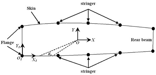
Wing stiffness centers were calculated for different cross-sections selected from root to tip. However, in the process of stiffness centers calculation, in order to facilitate calculation and programming, it is necessary to simplify the area and materials of different structures in the cross section. The beam edges and stringers are respectively equivalent to a point on the section, and different materials are equivalent to the same material. The simplified model for stiffness center calculation is shown in Figure 1.
| Figure 1. Simplified wing cross-section model |
2.1 Skin area
In order to obtain the stiffness data and the stiffness center position required for the aeroelastic analysis, the cross-sectional area of the skin is taken as the effective area, and the definite integral is used in the calculation process. The formula for calculating the cross-sectional area A of the skin in the interval [a, b] can be written as
|
|
(1) |
where represents the cross-sectional area of the skin and represents the thickness of the skin.
2.2 Stringer area
The stringer mainly bears the axial force caused by the bending moment of the wing. When establishing the stiffness center calculation model, the section is generally defined on the midplane of the skin, so that the cross-sectional area of the stringer should be converted. The simplified stringer is a rod with a concentrated area, and its entire area is concentrated on a point in the skin plane. The cross-sectional area of the stringer after conversion can be written as
|
|
(2) |
where, and are reduced and initial area, respectively, is the distance between skin and neutral surface of airfoil cross section and is the distance between stringer centroid and neutral surface of airfoil cross section.
2.3 stiffness center calculation
Cross-sectional area equivalent method based on sections 2.1 and 2.2 , in order to calculate the stiffness center for wing cross sections, first of all, we need to calculate the total area A of the components of the wing section under normal stress, and the centroid coordinates of the section denoted by and
|
|
(3) |
|
|
(4) |
|
|
(5) |
where is reduction factor, is the thickness of skin which number is , is the sum area of all component cross section, and are coordinate value and coordinate value of centroid, respectively.
According to coordinate transfer theory, in the area inertia coordinate and with individually representing wing chord and thickness orientation, the moment of inertia for every reduced cross sections on wing can be written as
|
|
(6) |
|
|
(7) |
Eq. (7) is the moment of the cross sections in the inertia axis, and then stiffness center of every cross section on wing can be calculated by Eq. (8) according to the thin wall structural mechanics theory
|
|
(8) |
where is twice the area of enclosed cross sections, and is the distance from the centroid to the tangent of each component.
3. The influence analysis of stiffness center on beam
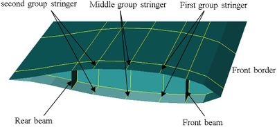
As the main frame, the wing beam plays an important role in wing structure. The wing stiffness center is impacted by beam dimensions and layouts. The influencing degree can be found eventually by comparing the different stiffness centers, which were gained by changing beam dimensions and layouts. Wing finite element model was shown in Figure 2.
| Figure 2. Wing finite element model |
3.1 Beam dimension
Stiffness center from wing root to tip is different. In order to research the impact of the beams, three wing stiffness centers are analyzed using three different wing models, which are original dimensions, enlarged beam dimensions and reduced beam dimensions at the same time, as shown in Table 1. The wing is divided into three sections according to different beam dimensions and numbers as shown in Figure 2.
| Model | Section A | Section B | Section C |
|---|---|---|---|
| Original | 3 | 2 | 2 |
| Enlarged | 3.5 | 2.5 | 2.5 |
| Reduced | 2.5 | 1.5 | 1.5 |
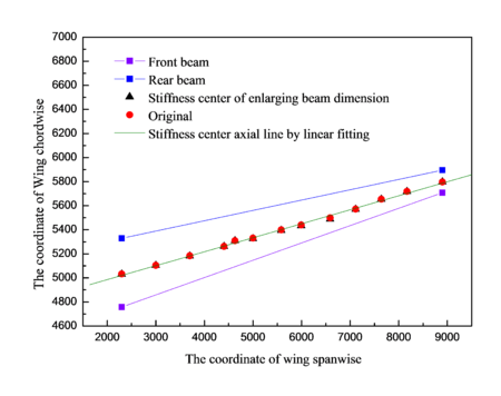
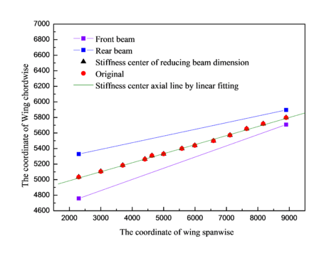
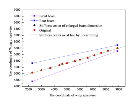
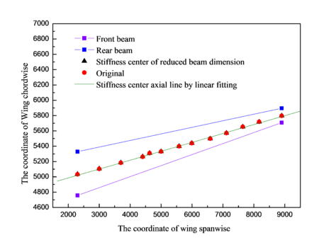
Wing cross section is shown in Figure 3. Stiffness center of enlarged beam dimension is compared with the original by linear fitting as shown in Figure 4. Similarly, the reduced beam dimension is also compared with the original by linear fitting as shown in Figure 5. Spacing of front beam and rear beam in the position of wing root is 560.606 mm, which is 197.08 mm in the position of wing tip. If denotes the distance between stiffness center and front beam, and denotes the distance between front beam and rear beam, then the value of () in the positions of wing root and wing tip under different models can be obtained, as shown in Table 2. It is indicated that the enlarged and reduced beam dimensions have small impact comparing with the original model.
| Figure 3. Wing cross sections |
| Figure 4. Stiffness center of enlarged beam and original |
| Figure 5. Stiffness center of reduced beam and original model |
| Original model (%) |
Enlarged beam dimension (%) |
Reduced beam dimension (%) | |
|---|---|---|---|
| Wing root | 44.7721 | 45.8022 | 46.3281 |
| Wing tip | 43.4955 | 42.4467 | 43.2312 |
3.2 Beam layout
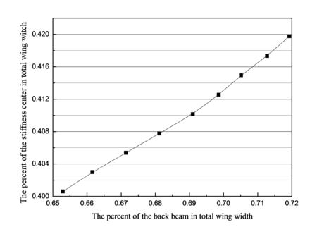
This section focused on the impact analyze of wing cross sections stiffness center on beam by comparing stiffness centers of different models. The percentage curves of the stiffness center with respect to the change of front beam and rear beam are shown in Figures 6 and 7 respectively.
| Figure 6. The percent curve of the stiffness center according to the changing of front beam |
| Figure 7. The percent curve of the stiffness center according to the changing of back beam |
The position of the stiffness center is impacted by the layout of the front beam and rear beam. The positions of them were defined by percent of the distance between them and the front border with respect to the total wing width. When changing the percent of the front beam positions from 15.343% to 21.98% of total wing width, the percent of the stiffness center positions varies from 40.176% to 42.128% correspondingly. Similarly, when changing the percent of the rear beam position from 65.288% to 71.926% of total wing width, the percent of the stiffness center positions varies from 40.061% to 41.976% correspondingly.
4. The influence analysis of stiffness center on stringer
4.1 Stringer dimension
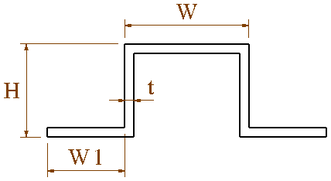
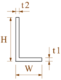
The change in the cross-sectional dimension of the stringer will affect the cross-sectional structure of the wing and at the same time affect the stiffness centerof the cross-sectional wing. In order to research the impact of the stringers, three wing stiffness centers were analyzed using three different wing models, which are original dimensions, enlarged stringer dimensions and reduce stringer dimensions at the same time, as shown in Table 3. Two Stringer cross sections are shown in Figure 8.
| Models | Top wing in section A | Down wing in section A | Wing in sections B and C | |||||||||
|---|---|---|---|---|---|---|---|---|---|---|---|---|
| W | H | t | W1 | W | H | t | W1 | W | H | t1 | t2 | |
| original | 40 | 30 | 3 | 25 | 30 | 30 | 3 | 25 | 15 | 25 | 2 | 2 |
| enlarge | 45 | 35 | 3.5 | 30 | 25 | 25 | 3.5 | 30 | 18 | 30 | 2.5 | 2.5 |
| reduce | 35 | 25 | 2.5 | 20 | 20 | 20 | 2.5 | 20 | 12 | 20 | 1.5 | 1.5 |
| (a) | (b) |
| Figure 8. Stringer cross-section. (a) Section A. (b) Sections B and C | |
These stiffness centers of the two wing models with enlarged stringer dimensions and original are compared, as shown in Figure 9. Similarly, these stiffness centers of the two wing models with reduced stringer dimensions and original model are also compared in Figure 10.
| Figure 9. Stiffness center of enlarged stringer and original model |
| Figure 10. Stiffness center of reduced stringer and original model |
The values of C in the positions of wing root and wing tip for different models can be obtained, as shown in Table 4. It is indicated that enlarged and reduced stringer dimensions have little impact comparing with the original model.
| Enlarged stringer dimension (%) |
Reduced stringer dimension (%) | |
|---|---|---|
| Wing root | 45.779 | 46.553 |
| Wing tip | 44.1105 | 43.3256 |
4.2 Stringer layout
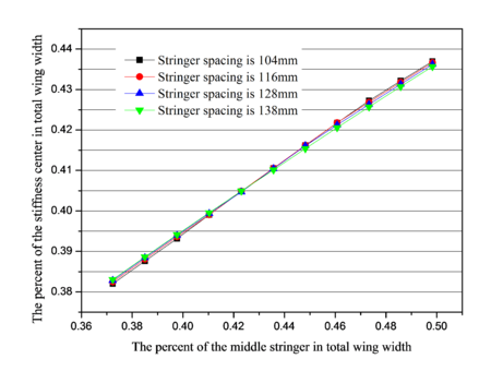
Wing stiffness centers were different for the different stringer layouts. In order to study the influence of the structural layout of the stringer on the stiffness center, it is necessary to keep the layout and dimensions of other cross-sectional structures unchanged to achieve the purpose of the research. Wing cross section is shown in Figure 3, different stiffness centers are gained when changing the middle group stringer position in the four models, which are shown in Figure 11.
| Figure 11. The percent curve of the stiffness center according to middle group stringer on different stringer spacing |
When changing the percentage of middle stringer positions of total wing width are from 37.232% to 49.828%, the percentage of the variation range of stiffness center positions in total wing width are individually shown in Table 5. It is indicated that stiffness center position has a great change for different models with different spacings of stringers, but has small impact on the spacing of stringers.
| Stringer spacing | Variation range of stiffness center (%) | |
|---|---|---|
| beginning | end | |
| 104 mm | 38.199 | 43.7 |
| 116 mm | 38.248 | 43.667 |
| 128 mm | 38.283 | 43.626 |
| 138 mm | 38.305 | 43.567 |
5. Sensitivity analysis for beam and stringer
Sensitivity is the derivative information, which reflects the impact of design variable on objective function or constraint function. The sensitivity formula for wing cross sections stiffness is derived according to the thickness of beam and stringer, which is written as
|
|
(9) |
with
|
|
As the distance between wing beam or middle group stringer and inertia axis of wing cross sections, the sensitivity formula for wing cross sections stiffness is derived as
|
|
(10) |
with
|
Mean value sensitivity reflects the influencing degree of the average value of variable for structure. According to the formulation (9), when enlarging or reducing the thicknesses of beam and stringer at the same time, the results of mean sensitivity for the stiffness center of wing cross sections for the thickness of beam and stringer are obtained in Table 6.
| Variables | Beams | Stringers |
|---|---|---|
| Mean value sensitivity | 1.691 | 0.0352 |
When researching the impact of the front beam and rear beam layouts for stiffness center, it is necessary to keep the positions of other structure while only change the position of front beam or rear beam. According to the Eq. (10), the results of mean sensitivity of beam positions of stiffness center are obtained in Table 7.
| Variables | Front beam | Rear beam |
|---|---|---|
| Mean value sensitivity | 0.2906 | 0.288 |
The distribution of the stringers for wing cross section was shown in Figure 2. In order to research the impact of different stringer spacing for stiffness center, 4 models with different stringer spacing were obtained. Change the position of stringers at the same time when middle group stringer is the design variable of sensitivity, the results of mean value sensitivity for stringer positions about stiffness center for different models are obtained in Table 8.
| Variables | Middle group stringer | |||
|---|---|---|---|---|
| Models | 1 | 2 | 3 | 4 |
| Mean value sensitivity | 0.4462 | 0.4413 | 0.4328 | 0.4174 |
We concluded that it has small impact by changing the beam and stringer thickness for position of stiffness center on full composite wing structure. However, it is large to the changing of the positions of front beam and rear beam. Comparing 4 different models with only different stringer spacing, it is found that the positions of wing cross sections stiffness center are all impacted largely for the 4 models.
6. Conclusion
This paper studies the influence of the size and layout of the stringers and beams on the stiffness center of the wing cross section. The sensitivity formulas for stiffness center of wing cross sections were derived and expressed in terms of variations with dimension and position of beam and stringer. The important conclusions obtained through the research are as follows:
- According to the impact analysis of beam and stringer for wing cross sections stiffness center, it is found that the stiffness centers of full composite wing are remarkable sensitive to structure layout of beam and stringer, which has small impact for the change of stringers spacing.
- Based on the formula of stiffness center, sensitivity formulas for stiffness center were derived, which was used accurately in analyzing the impact of beam and stringer. This effect of the structure layout of beam and stringer are considered as an important factor in stiffness design of full composite wing structure.
- The influence analysis and sensitivity of stiffness are very useful in the design of full composite wing structure.
Acknowledgments
This work is funded by the Scientific Research Foundation for Doctors, the Natural Science Basic Research Plan in Shaanxi Province of China (No: 2019JQ-912) and the Natural Science Foundation of Xi′ an Aeronautical University (No: 2018KY1226).
References
[1] Guan D., Zhong K. Aeroelastic tailoring applied to composite wing. Acta Aeronautica et Astronautica Sinica, 10(5):221-226, 1989.
[2] Huo S.H., Wang F.S., Yuan Z., Yue Z.F. Composite wing elastic axis for aeroelasticity optimization design. Aircraft Engineering and Aerospace Technology, 85(1):10-15, 2013.
[3] Guyan R.J. Reduction of stiffness and mass matrices. AIAA Journal, 13(2):380-385, 1965.
[4] Hanegan S.J. Advanced flexible wing technology assessment for transport applications. Massachusetts Institute of Technology, US, 1995.
[5] Liu Y.C., Huang G.N., Wang L.J. Computation of stiffness characteristic of a high aspect ratio wing. Airplane Engineering, 4:21-24, 2006.
[6] Ye Z.Y., Xie Y.J., Wu J. The effects of wind-tunnel model vibration on flow field and aerodynamics of an airfoil. Engineering Mechanics, 26(4):240-245, 2009.
[7] Cesnik C.E.S., Mok J., Parikh A.S. Optimization design framework for integrally twisted helicopter blades. AIAA 2004-1761, 4:1-15, 2004.
[8] Li D.C., Xiang J.W. Nonlinear aeroelastic analysis of airfoil using quasi-analytical approach. Acta Aeronautica Et Astronautica Sinica, 28(5):1080-1084, 2007.
[9] Haftka R.T., Addlman H.M. Recent developments in structural sensitivity analysis. Structural Optimization, 3(1):137-152, 1989.
[10] Wang S.Y., Sun Y., Gallagher R.H. Sensitivity analysis in shape optimization of continuum structures. Computers and Structures, 20:855-867, 1985.
[11] Pandey P.C., Bakshi P. Analytical response sensitivity using hybrid finite elements. Computers and Structures, 70:525-534, 1999.
[12] Tafreshi A. Shape design sensitivity analysis with respect to the positioning of features in composite structures using the boundary element method. Engineering Analysis with Boundary Elements, 30:1-13, 2006.
[13] Choi J.H. Shape design sensitivity analysis for stability of elastic continuum structures. International Journal of Solids and Structures, 44:1593-1607, 2007.
[14] Choi J.H. Shape design sensitivity analysis and optimization of general plane arch structures. Finite Elements in Analysis and Design, 39: 119-136, 2002.
[15] Antonio C.C., Hoffbauer L.N. Uncertainty analysis based on sensitivity applied to angle-ply composite structures. Reliability Engineering and System Safety, 92:1353-1362, 2007.
[16] Hien T.D., Kleiber M. Stochastic structural design sensitivity of static response. Computers and Structures, 38(5/6):659-667, 1991.
[17] Sergeyey O., Mroz Z. Sensitivity analysis and optimal design of 3D frame structures for stress and frequency constraints. Computers and Structures, 76:167-185, 2000.
[18] Wang Z.D., Chen S.H. Sensitivity analysis of eigenmodes and dynamic responses for intelligent structures. Finite Elements in Analysis and Design, 33:71-81, 1999.
[19] Zhao Y., Wang F.Y. Sensitivity analysis for structures subjected to stationary random excitations. Procedia Engineering, 14:2475-2480, 2011.
[20] Ohsaki M. Design sensitivity analysis and optimization for nonlinear buckling of finite-dimensional elastic conservative structures. Comput. Methods Appl. Mech. Engrg., 194:3331-3358, 2005.
[21] Petrov E.P. Analysis of sensitivity and robustness of forced response for nonlinear dynamic structures. Mechanical Systems and Signal Processing, 23:68-86, 2009.
[22] Etienne S., Pelletier D. A general approach to sensitivity analysis of fluid-structure interactions. Journal of Fluids and Structures, 21:169-186, 2005.
[23] Kim M.G, Jang H.L., Cho S. Adjoint design sensitivity analysis of reduced atomic systems using generalized langevin equation for lattice structures. Journal of Computational Physics, 240:1-19, 2013.
[24] Pajot J.M., Maute K. Analytical sensitivity analysis of geometrically nonlinear structures based on the co-rotational finite element method. Finite Elements in Analysis and Design, 42:900-913, 2006.
[25] Mang H.A., Hofinger G., Jia X. On the interdependency of primary and initial secondary equilibrium paths in sensitivity analysis of elastic structures. Comput. Methods Appl. Mech. Engrg., 200:1558-1567, 2011.
Document information
Published on 28/09/21
Accepted on 10/09/21
Submitted on 21/12/20
Volume 37, Issue 3, 2021
DOI: 10.23967/j.rimni.2021.09.009
Licence: CC BY-NC-SA license
Share this document
Keywords
claim authorship
Are you one of the authors of this document?
