Abstract
Recently wireless sensor network (WSN) has been widely used for monitoring railway tracks and rail tunnels. The key requirement in the design of such WSN is to minimize the energy consumption so as to maximize the network lifetime. This paper includes the performance of an improved medium access control (MAC) protocol, namely, time adaptive-bit map assisted (TA-BMA) protocol, for the purpose of communication between the sensors placed in a railway wagon. The train is considered to be moving at a constant speed, and the sensor nodes are stationary with respect to the motion of train. The effect of mobility on the proposed MAC protocol is determined using genetic algorithm (GA), and the observed increase in energy consumption on considering mobility is 18.51%. Performance analysis of the system model is carried out using QualNet (ver. 7.1), and the energy consumption in transmit mode, receive mode, percentage of time in sleep mode, end-to-end delay and throughput are investigated.
Keywords
Wireless sensor network (WSN) ; Medium access control (MAC) ; Time adaptive bit map assisted protocol (TA-BMA) ; Genetic algorithm (GA) ; Railway wagon
1. Introduction
Wireless sensor network (WSN) consists of a large number of distributed sensor nodes which can be used to sense data from the physical environment [1] and [2] . These types of networks have many practical applications, and in this paper their applications in railway monitoring systems are discussed. WSNs are used to monitor railway tracks, rail tunnels, detect abandoned bodies in railway platforms, develop intrusion detection systems and secure railway operations. Due to the lack of safety and security monitoring, the railway runs the risk of train collision, derailment and possible terrorist threats [3] . Sensor network applications require long lifetime, data accuracy, and energy efficiency. Hence, power management is an important design constraint for WSNs. This is because sensor nodes are equipped with battery of short life, and they should use it efficiently in cases where the system operates for long durations [3] and [4] .
Sensor nodes consume energy while sensing, processing and communicating sensed data. Each node can transmit only a fixed number of bits and in case a node has a heavy burden of communication, it gets depleted fast, thus affecting the entire network [5] . In WSN, major waste of energy happens due to collision, idle listening, overhearing, presence of overhead, etc. Various energy saving methods are proposed for medium access control (MAC) protocols in WSN to avoid wasting the limited energy [3] and [6] . Energy efficient MAC is necessary for the successful operation of shared medium networks. The MAC can be of contention based or schedule based protocol. Among these protocols, schedule based protocols are collision free and thus save energy wasted due to collision.
In Reference 6 , scheduled-based Time-division multiple access protocol (TDMA) has been discussed, in which the transmission channel is divided into several time slots and each node is assigned a time slot. Each node wakes up and transmits data only in its allocated time slots and remains in sleep mode at other times. This protocol is energy efficient only when the traffic load is high. In Reference 3 , an energy efficient adaptive TDMA (EA-TDMA) protocol has been proposed, where every node wakes up in its allocated time slot and checks transmit buffers. If there are no data to transmit, it turns off the radio immediately. This protocol reduces energy consumption by idle listening.
In Reference 1 , a bit map assisted (BMA) protocol intended for event-driven applications have been proposed, where sensor nodes transmit data to cluster head only if significant events are observed. Here time slot is allocated in the contention phase before starting of each frame unlike in TDMA and EA-TDMA where a data slot allocated to a node persists for all frames in that round. In Reference 7 , an energy efficient bit map assisted protocol (E-BMA) has been proposed, in which the source nodes use piggybacking to make reservation of the corresponding data slot. Unlike BMA, it does not make reservation in the contention slot as soon as the data packet is available, but it waits for one additional frame duration to see if there is a successive data packet to send. This protocol is energy efficient at low and medium traffic.
In this paper, a time adaptive bit map assisted protocol (TA-BMA) has been proposed considering node placement in wagon. This protocol uses clustering techniques to monitor vertical acceleration and lateral instability of railway wagons. In this protocol, each node wakes up in its allocated time slot but goes to idle immediately after data transfer is over. A mathematical model has been developed to evaluate the performance of this cluster-based TA-BMA protocol. This paper also focuses on the various deployment scenarios of sensor nodes inside train wagons, namely, four sensor nodes placed at four corners of wagon, eight nodes at four corners, eight nodes at four corners of which four nodes are active first and remaining nodes become active when the first four nodes die, and four nodes at four corners in which corner node with maximum energy becomes cluster head as prevailing cluster head dies.
The remainder of the paper is organized as follows. Section 2 gives the description of TA-BMA protocol. The proposed protocol monitors vertical acceleration and lateral instability of railway wagons. This protocol also aims to reduce energy dissipation in sensor nodes. Need for mobility and effect of mobility on proposed protocol is discussed in Section 3 . For determining the effect of mobility, genetic algorithm is analyzed for the train scenario. Various deployment scenarios of sensor nodes inside train wagon are discussed in Section 4 . Mathematical analysis for these scenarios is also included. Simulation environment along with simulation parameters used in QualNet is given in Section 5 . Results and discussion is detailed in Section 6 and Section 7 concludes the paper.
2. Time adaptive bit map assisted (TA-BMA) protocol
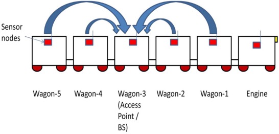
The system model considered in this paper is a train with a number of wagons. Each wagon is equipped with five sensor nodes. Of these, four nodes are placed at each corner of the wagon and one node at the center of the wagon. Center node is the cluster head (CH), and access point or base station (BS) is placed at the middle wagon of the train. CH collects data from the corner nodes and aggregates the received data onto its own data and forwards these data to BS. The sensed data received at BS is monitored through an audio or visual system by locomotive driver, and then decisions are taken accordingly [3] . A prototype of the system model is given in Fig. 1 .
|
|
|
Fig. 1. Prototype of the system model.
|
The vertical and lateral accelerations of the railway wagon are determined using accelerometers (ADXL 202/ADXL 210). From this, dynamic behavior between rail track and railway wagon is determined. For reliable wireless monitoring IEEE 802.15.4/ZigBee is used which focuses on low data rate and low power. Communication between sensor nodes placed inside rail wagon is carried out using ZigBee [2] , [3] and [4] . Here packets are transmitted by means of unicast forwarding, i.e. a source transmitting data packets to a single destination. Routing protocol used is ad-hoc on demand routing (AODV). When a node wants to start a communication process, it begins a path discovery process to discover the other node [5] and [8] .
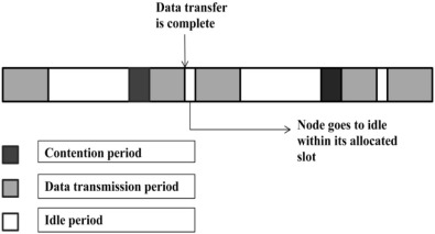
In time adaptive bit map assisted (TA-BMA) protocol, source nodes use piggybacking to make reservation of the corresponding data slot. It does not make reservation in the contention slot as soon as the data packet is available, but it waits for one additional frame duration to see if there is a successive data packet to send. Here, the time slot allocated is fixed and source node remains awake throughout the slot. This node has to be in active mode in its allocated time slot even when the data transfer is complete. TA-BMA is introduced to address this problem. Fig. 2 . illustrates the operation diagram of TA-BMA.
|
|
|
Fig. 2. Timing operation of TA-BMA.
|
Nodes in TA-BMA go to idle when data transfer is completed. This reduces energy consumption by shortening the active period of nodes in their respective time slots and thus makes it suitable for low to medium traffic. As in E-BMA, TA-BMA also has to compromise on the latency of data transmission because each data packet has to wait for one additional frame duration before being transmitted to the CH.
3. Various deployment scenarios of sensor nodes inside train wagons
There are various ways by which sensor nodes can be placed inside train wagons. Throughput alters for various deployment scenarios. The scenario with maximum throughput or with minimum number of dead nodes can be chosen for the proposed model. Various scenarios are discussed below:
- Four nodes at four corners and CH at middle of the wagon.
- Eight nodes at four corners and CH at middle of the wagon.
- Eight nodes at four corners of which only four nodes are active first and the rest are in sleep mode. The sleep nodes become active when the first four nodes die. CH is at the middle of the wagon. This arrangement is used to maintain sensing and connectivity.
- Four nodes at four corners and CH at middle of the wagon. When CH dies, the corner node with maximum energy becomes CH.
3.1. Analytical analysis for the proposed scenarios
For all the above cases, non-CHs sense data and transmit it to CH. The data are received by CH where it is aggregated and forwarded to access point. Data transmitted by a node are taken as . Data received by CH is and forwarded to sink are . Energy consumed by a node (N) to transmit data to CH is , and when the distance (d) between them is less than the threshold distance d0 (free space) then,
|
|
( 1) |
When d ≥ do (multipath)
|
|
( 2) |
Energy consumed by CH to transmit data to sink is , when distance (d) between them is less than d0 then,
|
|
( 3) |
When d ≥ d0
|
|
( 4) |
where is the length of the data packet from node to CH, is the length of the data packet from CH to sink, , is the energy dissipated to drive the transmitter or receiver circuitry, is the energy consumed during data aggregation, is the energy consumed by the transmitter amplifier assuming a free-space (d2 ) energy loss model and is the energy consumed by the transmitter amplifier assuming a free-space (d4 ) energy loss model [9] .
4. Effect of mobility through genetic algorithm
The train is considered to be moving at a constant speed, and the sensor nodes are stationary with respect to the motion of train. Thus, the effect of mobility on the proposed MAC protocol is determined using genetic algorithm (GA). It is motivated by the way biological chromosomes training genetic material mutate and cross over to produce better chromosomes in off-springs through a set of generations. Superior off-springs survive, whereas the inferior ones expire. The GA design consists of a fitness function that is used to evaluate the fitness of possible chromosomes, where a higher fitness indicates a better chromosome. In the proposed system, value_opt is considered as a measure of fitness and the objective of GA in these train scenarios is to find the chromosome that minimizes the value_opt. Hence, the objective is to reduce the value_opt so that the fitness is improved. The value_opt is proportional to the sum of two parameters, namely, energy consumption during transmission and total speed of nodes, cluster head and base station [4] , [10] and [11] . The speed of the base station is also considered as the base station is also present in the moving train.
If n_CH refers to the number of cluster heads and n_CH_nodes refers to the number of cluster members, then the total number of nodes in a train (N_Train) is given as follows,
|
|
( 5) |
The cluster head of a particular wagon (CH_Wagon) is chosen as follows,
|
|
( 6) |
The speed of the cluster head, nodes and the base station is considered as follows,
|
|
( 7) |
where Sn_CH refers to the speed of the cluster head, Sn_CH_nodes refers to the speed of the cluster head and SBS refers to the speed of the base station.
The total energy of the cluster members (E_n_CH_nodes) is the total energy consumed for transmitting per unit of information from each cluster member to its corresponding cluster head in all the wagons (E_nodes_T) and the energy spent by the cluster head to process the information (E_CH) and it is computed as follows:
|
|
( 8) |
where i ∈ n_CH_nodes, j ∈ n_CH and m are the number of data bytes transmitted by the nodes to CH.
The total energy of the cluster head (E_n_CH) is the total energy consumed on transmitting the aggregated information from each cluster head to the base station.
|
|
( 9) |
where E_BS is the energy spent by the base station to process the information that is transmitted from the cluster head.
The fitness value (value_opt) to be optimized is calculated as follows:
|
|
( 10) |
where αE_T ∈ (0,1)and βS_Train ∈ (0,1) refers to the scaling or smoothing factors that add weight to the parameters of the fitness function. Also, E_T_est and S_Train_est refer to the estimated total energy and speed, respectively. From Eq. (10) it could be understood that a proper balance is provided for obtaining the optimum value as fractional changes in the value of the parameters will affect the overall energy consumption of the network. Since, E_T and S_Train is ever changing, in practice, the value of E_T has to be updated for each transmission so as to reflect the real train scenario. Such empirical will result in the rapid fluctuation of E_T and S_Train. Hence, the value to be optimized is the weighted combination of the current value (estimated) and the previous values.
5. Simulation environment
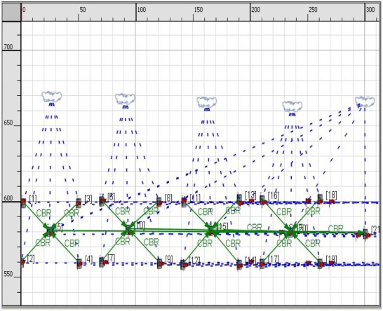
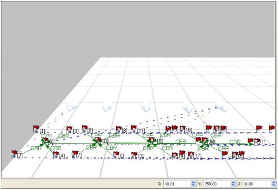
The proposed model is evaluated by QualNet (7.1) simulator. Fig. 3 and Fig. 4 displays the snapshots of the scenario implemented in QualNet. In the simulated scenario, there are 20 nodes and a BS placed within a 700 m × 700 m area. Nodes 1 through to 20 are source nodes that are deployed in the train wagon of which nodes 5, 10, 15 and 20 are the CHs and node 21 is the BS. Corner nodes sense data and send the data to the CH which is then forwarded to BS. Corner nodes are made reduced function device (RFD) and CHs and BS are made full function device (FFD). Simulation time used is 5 minutes. The number of constant bit rate (CBR) connections is 10. Two ray ground propagation models are used for wireless propagation. Nodes are fixed on train wagon and train is moving at a constant speed. The movement of nodes is shown using flags for each node. The simulation parameters are listed in Table 1 .
|
|
|
Fig. 3. 2D view of system model in QualNet.
|
|
|
|
Fig. 4. 3D view of system model in QualNet.
|
| Parameter | Value |
|---|---|
| Simulation area | 700 m × 700 m |
| Number of nodes | 21 |
| Channel frequency | 2.4 GHz |
| Data rate | 40 kbps |
| Network protocol | IPV4 |
| Path loss model | Two ray |
| Radio type | IEEE 802.15.4 |
| Packet reception model | PHY 802.15.4 |
| Modulation scheme | OQPSK |
| MAC layer protocol | IEEE 802.15.4 |
| Routing protocol | AODV |
| Traffic type | CBR |
| Antenna model | Omni-directional |
| Device type corner nodes | RFD |
| Device type CH | FFD (PAN coordinator) |
| Energy model | MicaZ |
6. Results and discussion
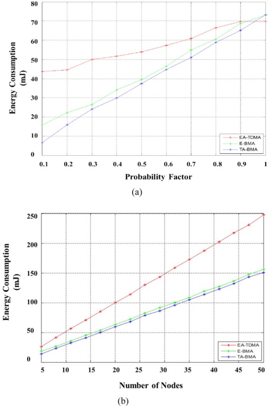
The performance of the TA-BMA protocol considering mobility is analyzed. The Zigbee enabled 2.4 GHz CC2420 RF transceiver uses 50 mW for transmitting, 54 mW for receiving and 50 mW for idle listening. The data rate is 25 kbps. Assume a data packet size of 100 bytes and a control packet size of 5 bytes [13] , [14] , [15] , [16] and [17] . Fig. 5(a) gives the comparison of TA-BMA, E-BMA and EA-TDMA protocols as a function of probability p. Here, p is the probability of a data packet not being piggybacked, N is the number of nodes and L is the frames per round. The proposed protocol TA-BMA outperforms all other protocols significantly. But at high traffic load when p ≥ 0.9, TA-BMA is outperformed by EA-TDMA. The percentage increase in energy consumption with respect to TA-BMA for EA-TDMA is 29.20% and E-BMA is 6.39%.
|
|
|
Fig. 5. Energy consumption for (a) varying probability factor of N = 10 and L = 2 and (b) varying number of nodes for p = 0.4 and L = 2.
|
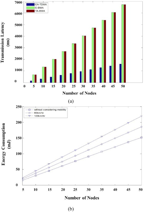
Fig. 5(b) gives the comparison of different protocols as a function of number of nodes N, taking p = 0.4 and L = 2. The performance of TA-BMA is the best at medium traffic (p = 0.4) followed by E-BMA and EA-TDMA. The energy consumption in TA-BMA is reduced by 39.7% and 5.18% with EA-TDMA and E-BMA, respectively. Fig. 6(a) gives variation of maximum transmission latency with respect to number of nodes. From the graph, it is evident that the transmission latency increases with number of nodes. The TA-BMA and E-BMA scheme display very high transmission latency as compared to EA-TDMA.
|
|
|
Fig. 6. (a) Transmission latency with increase in the number of nodes and (b) energy consumption for varying number of nodes considering mobility.
|
Fig. 6(b) gives the energy consumption of TA-BMA protocol for varying number of nodes considering mobility at different train speeds. Speed is varied from 60 km/h to 120 km/h. From the graph it is observed that as speed increases, total energy consumed also increases. At 60 km/h, total energy consumed is 300 J. At 120 km/h, total energy consumed is 600 J. Taking numbers of nodes as 20, the total energy consumed without considering mobility is 50 mJ. At 60 km/h total energy consumed is 75 mJ and at 120 km/h total energy consumed is 100 mJ. Thus energy consumption increases on considering mobility. Energy consumed is more in the case of 120 km/h.
6.1. Possible arrangements of sensor nodes inside wagons
The investigation on the possible arrangement of sensor nodes inside wagons and the election of the cluster head has been analyzed through various scenarios. Fig. 7(a) displays the arrangement of four nodes at four corners and CH at middle of the wagon, and Fig. 7(b) shows the arrangement of eight nodes at four corners and CH at middle of the wagon.
|
|
|
Fig. 7. (a) Case 1 – Four nodes at four corners and CH at middle of the wagon and (b) Case 2 – Eight nodes at four corners and CH at middle of the wagon.
|
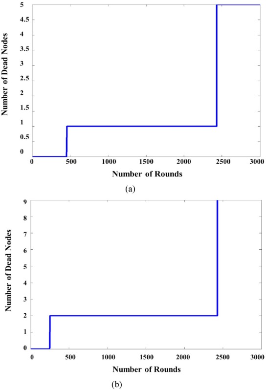
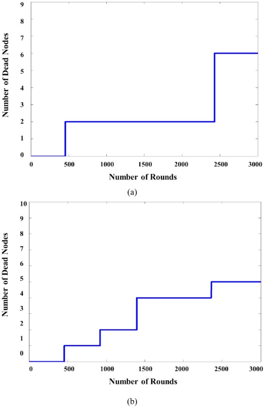
As the number of nodes increases the CH tends to spend its energy at a faster rate. Hence, the election of CH has to be carried out dynamically as the number of nodes increases. Also, the nodes have to follow a power saving mechanism to alter their active and sleep modes. Fig. 8(a) displays the eight nodes at four corners of which only four nodes are active first and the rest are in sleep mode and CH at middle of the wagon. Also, Fig. 8(b) shows the case of four nodes at four corners and CH at middle of the wagon. When CH dies, the corner node with maximum energy becomes CH. It is evident that the number of dead nodes decreases with increase in the number of rounds.
|
|
|
Fig. 8. (a) Case 3 – Four nodes in random are active first and the rest are in sleep mode and CH at middle of the wagon and (b) Case 4 – Dynamic election of CH through genetic algorithm.
|
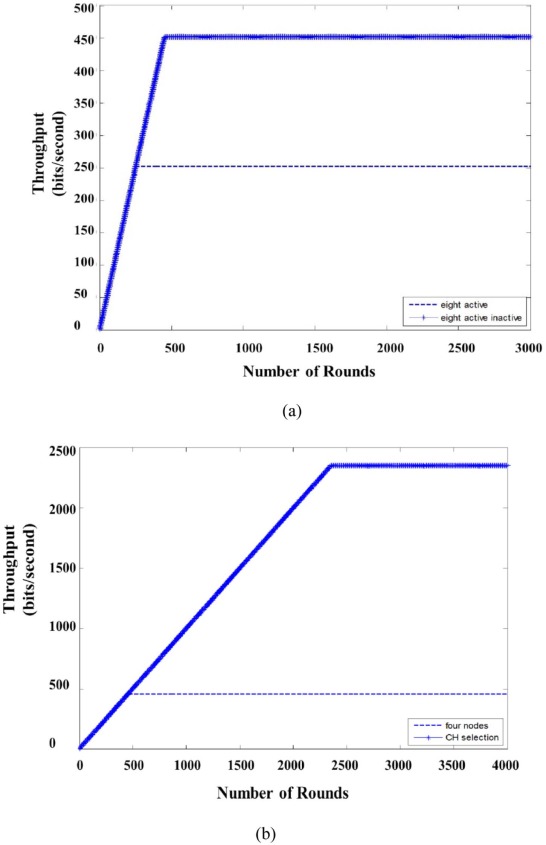
Fig. 9(a) compares the throughput of two cases. In Case 2, where all the eight nodes are active together, there is less throughput when compared to Case 3, where only four nodes are active first and the rest are in sleep mode. In Case 2, all eight nodes die at round 250 and thus no more packets are forwarded to CH. In Case 3, four active nodes die at round 250 and the remaining four nodes which were in sleep mode become active. These remaining nodes can be active for another round of 250, thus Case 3 has a lifetime of total number of rounds equal to 500. Fig. 9(b) compares the throughput of Case 1 and Case 4. In Case 1, where all the four nodes are active together, there are fewer throughputs when compared to Case 4 where a corner node acts as a CH as CH dies. Throughput is calculated on the basis of number of packets sent to base station. Packets are forwarded to BS as long as CH is alive. In Case 1, CH dies before round 500. In Case 4, CH dies before round 500, but the corner node with maximum energy becomes CH.
|
|
|
Fig. 9. Throughput comparison of (a) Case 2 and Case 3 and (b) Case 1 and Case 4.
|
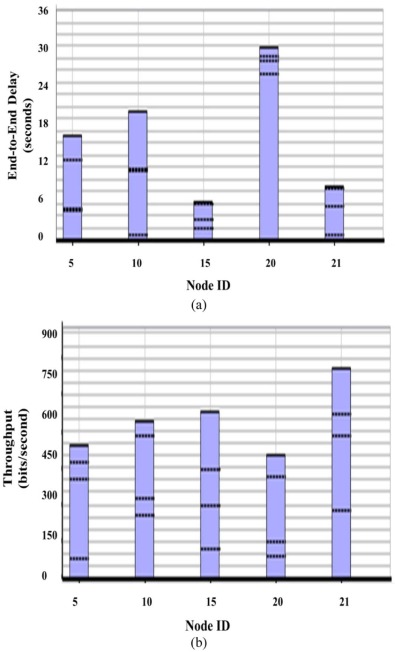
The system modeled in Qualnet 7.1 consists of 20 nodes placed inside train wagons. They are indexed from 1 to 20. Among these, nodes with index 5, 10, 15 and 20 are taken as cluster heads and the remaining are corner nodes or non CHs. Corner nodes sense data and send it to CHs which are then forwarded to Base Station (BS). It is indexed as 21. Fig. 10(a) gives the average unicast end to end delay of all CHs and BS in seconds. This gives the period between the data packets generation time and the last bit arrival time at the destination [10] . CH 20 has maximum end to end delay (32 seconds) and CH 15 has minimum end to end delay (6 seconds). BS has comparatively less delay (8 seconds).
|
|
|
Fig. 10. (a) Average unicast end to end delay and (b) unicast received throughput.
|
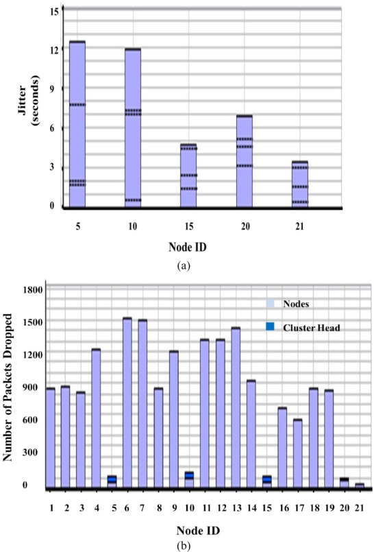
Fig. 10(b) shows unicast received throughput with corresponding node indexes. Throughput gives the portion of the channel capacity utilized for useful transmission [10] . It is calculated in bits per second (bps). This graph depicts the successful data received by CHs and BS. BS has maximum throughput (850 bytes). CH 20 has minimum throughput (450 bytes). BS receives maximum number of successful data when compared to CHs. Fig. 11(a) shows average unicast jitter with corresponding node indexes. Average jitter is the time difference in packet inter-arrival time to their destination [12] . CH 5 has maximum jitter (12 seconds). BS has minimum jitter (3 seconds). BS receives packet with minimum jitter.
|
|
|
Fig. 11. (a) Average unicast jitter and (b) number of packets dropped.
|
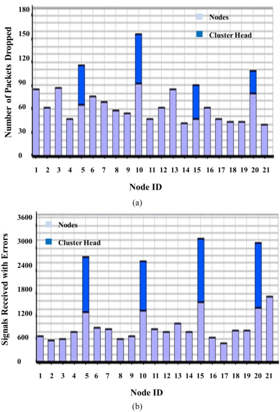
Fig. 11(b) gives the number of packets dropped with corresponding node indexes. Packets dropped by CHs are less when compared to corner nodes. BS (node 21) dropped minimum number of packets. Corner nodes dropped maximum number of packets around 900 to 1500. Fig. 12(a) shows number of data packets dropped due to channel access failure. This gives the number of packets dropped when the channel is proceeding to failure point. CH 10 drops maximum number of packets, i.e. 150 packets. Corner nodes drop less number of packets when compared to CHs. Corner node 4 drops 50 packets.
|
|
|
Fig. 12. (a) Number of packets dropped due to channel access failure and (b) signals received but with errors.
|
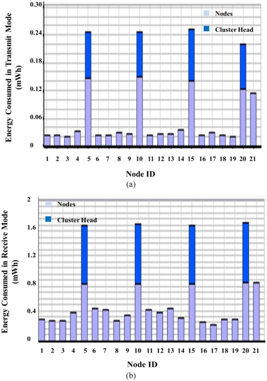
Fig. 12(b) shows the signals received but with errors. CHs received data with maximum errors which are followed by BS. CHs received signals with errors around 2600 to 3200. Corner nodes received data with less error (less than 800). Fig. 13(a) gives the energy consumed by nodes in transmit mode. CHs consumed maximum energy in transmit mode as CH forwards all data packets to BS. Energy consumed by CHs is in the range of 0.26 mWh. BS consumed 0.14 mWh in transmit mode. Corner nodes consumed less energy in transmit mode (0.02 mWh).
|
|
|
Fig. 13. (a) Energy consumed in transmit mode and (b) energy consumed in receive mode.
|
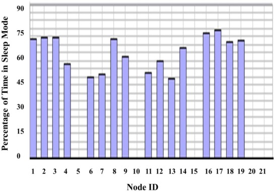
Fig. 13(b) gives the energy consumed by nodes in receive mode. CHs consumed maximum energy in receive mode as it receives all sensed data from corner nodes. Energy consumed by CHs lies between 1.6 to 2 mWh. After CHs, BS consumes maximum energy in receive mode, i.e. 0.9 mWh. Energy consumed by all corner nodes in receive mode is comparatively less. Fig. 14 gives the percentage of time of the nodes in sleep mode. As CHs are continuously receiving and forwarding packets, it cannot be in sleep mode. Similarly BS is also receiving packets that are forwarded by CHs. When nodes are not sensing data, it can remain in sleep mode. Thus only corner nodes stayed in sleep mode.
|
|
|
Fig. 14. Percentage of time the nodes are in sleep mode.
|
6.2. Comparison between BS at the middle and in the front wagon of the train
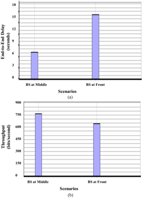
Fig. 15(a) compares unicast end to end delay of two scenarios, i.e. placing BS at middle wagon of the train and placing BS at front wagon of the train. The scenario with BS at front wagon of the train has high end to end delay (17 seconds), and the scenario with BS at middle wagon has low end to end delay (6 seconds). By considering the factor of end to end delay, scenario with BS at middle is observed well. Fig. 15(b) compares the unicast received throughput of BS at middle and front wagon scenarios. BS at front has fewer throughputs (650 bits/second) whereas BS at middle has high throughput (750 bits/second). Thus scenario with BS at middle can be chosen for optimal data transmission as it has low end to end delay and high throughput.
|
|
|
Fig. 15. (a) Average unicast end to end delay and (b) unicast received throughput.
|
7. Conclusion
In this paper, considering traffic load of the application, an energy efficient WSN MAC protocol has been investigated to monitor dynamic behaviors of railway wagons. Effect of mobility on TA-BMA protocol has been observed. Percentage increase in energy consumption on considering mobility is 18.51%. Different scenarios for deploying sensor nodes have been discussed and the best scenario for the system model has been found. Four nodes active and four nodes on sleep state scenario and the scenario in which the node with maximum energy was made CH turned out to be the best scenario. Real time analysis of the system has been examined through QualNet. Plotted different parameters of the scenario were created such as average unicast end to end delay, unicast received throughput, average unicast jitter, number of packets dropped, number of packets dropped due to channel access failure, signals received but with errors, energy consumed in transmit mode, energy consumed in receive mode and percentage of time in sleep mode. Placing BS at the middle wagon of the train is chosen for optimal data transmission as it gives high throughput and low end to end delay.
References
- [1] J. Li, G.Y. Lazarou; A bit-map-assisted energy-efficient MAC scheme for wireless sensor networks; Proceedings of 3rd International Symposium on Information Processing in Sensor Networks (IPSN) (2004), pp. 55–60
- [2] D.S.S. Rhee, S. Liu; Techniques for minimizing power consumption in low data-rate wireless sensor networks; Proceedings of Wireless Communications and Networking Conference (2004), pp. 1727–1731
- [3] G.M. Shafiullah, S.A. Azad, A.B.M.S. Ali; Energy-efficient wireless MAC protocols for railway monitoring applications; IEEE Trans. Intell. Transp. Syst, 14 (2) (2013), pp. 649–659
- [4] S. Lindsey, C.S. Raghavendra; Pegasis: Power-efficient gathering in sensor information systems; Aerospace Conference Proceedings, 2002, vol. 3, IEEE (2002), pp. 3-1125–3-1130
- [5] A. Agrawal, R. Thalore Manju, V. Raina, M.K. Jyoti Jha; Effects of different topologies on network lifetime in WSN; Int. J. Sci. Eng. Res, 4 (11) (2013)
- [6] F. Akyildiz, W. Su, Y. Sankarasubramaniam, E. Cayirci; A survey of sensor networks; IEEE Commun. Mag, 40 (8) (2002), pp. 102–114
- [7] G.M. Shafiullah, A. Thompson, P. Wolfs, S. Ali; Energy-efficient TDMA MAC protocol for wireless sensor networks applications; Proceedings of 11th International Conference on Computer and Information Technology (ICCIT 2008) (2008), pp. 85–90 December 24–27
- [8] C.P.E. Aboelela, W. Edberg, V. Vokkarane; Wireless sensor network based model for secure railway operations; Proceedings of 25th IEEE Performance, Computing, and Communications Conference (2006), pp. 623–628
- [9] M.B. Rasheed, N. Javaid, Z.A. Khan, U. Qasim, M. Ishfaq; E-Horm: an energy-efficient hole removing mechanism in wireless sensor networks; Proceedings of 26th IEEE Canadian Conference on Electrical and Computer Engineering (CCECE2013) (2013), pp. 1–4
- [10] S. Sarangi, S. Kar; Genetic Algorithm Based Mobility Aware Clustering for Energy Efficient Routing in Wireless Sensor Networks; IEEE (2011)
- [11] E. Heidari, A. Movaghar; Intelligent clustering in wireless sensor networks; Proceedings of the 2009 First International Conference on Networks and Communications, Ser. NETCOM ‘09, IEEE Computer Society, Washington, DC, USA (2009), pp. 12–17
- [12] R. Thalore Manju, M.K. Jyoti Jha; Performance evaluation of Bellman-Ford, AODV, DSR and DYMO protocols using QualNet in 1000 m × 1000 m terrain area; Int. J. Soft Comput. Eng, 2 (6) (2013), pp. 144–149
- [13] ADXL202E-low-cost-2 g dual-axis accelerometer with duty cycle output – analog devices, analogue devices; [Online] http://www.alldatasheet.com/datasheet-pdf/pdf/48922/AD/ADXL202E.html
- [14] W. Ye, J. Heidemann, D. Estrin; An energy efficient MAC protocol for wireless sensor networks; Proceedings of the IEEE INFOCOM (2002), pp. 1567–1576
- [15] IEEE; IEEE Standard 15.4: Wireless Medium Access Control (MAC) and Physical Layer (PHY) Specifications for Low-Rate Wireless Personal Area Networks (LR-WPAN); 802.15.4 IEEE Computer Society, New York (2003)
- [16] R.S. Bhuvaneswaran, J.L. Bordim, J. Cui, K. Nakano; Fundamental protocols for wireless sensor networks; Proceedings of 15th International Parallel and Distributed Processing Symposium (2001), pp. 1369–1376
- [17] M. Uzzwal, R. Sharma; Energy efficient MAC protocol & radio energy model for AODV & Bellman Ford routing protocol; IOSR J. Electron. Commun. Eng, 9 (1) (2014), pp. 44–50
Document information
Published on 10/04/17
Licence: Other
Share this document
Keywords
claim authorship
Are you one of the authors of this document?

