Published in Computational Plasticity, E. Oñate and R. Owen (Eds.), pp. 239-265, 2007
DOI: 10.1007/978-1-4020-6577-4_14
Abstract
An enhanced rotation-free three node triangular shell element (termed EBST) is presented. The element formulation is based on a quadratic interpolation of the geometry in terms of the six nodes of a patch of four triangles associated to each triangular element. This allows to compute an assumed constant curvature field and an assumed linear membrane strain field which improves the in-plane behaviour of the element. A simple and economic version of the element using a single integration point is presented. The implementation of the element into an explicit dynamic scheme is described. The efficiency and accuracy of the EBST element and the explicit dynamic scheme are demonstrated in many examples of application including the analysis of a cylindrical panel under impulse loading and sheet metal stamping problems.
1 Introduction
Triangular shell elements are very useful for the solution of large scale shell problems occurring in many practical engineering situations. Typical examples are the analysis of shell roofs under static and dynamic loads, sheet stamping processes, vehicle dynamics and crash-worthiness situations. Many of these problems involve high geometrical and material non linearities and time changing frictional contact conditions. These difficulties are usually increased by the need of discretizing complex geometrical shapes. Here the use of shell triangles and non-structured meshes becomes a critical necessity. Despite recent advances in the field [1-6] there are not so many simple shell triangles which are capable of accurately modelling the deformation of a shell structure under arbitrary loading conditions.
A promising line to derive simple shell triangles is to use the nodal displacements as the only unknowns for describing the shell kinematics. This idea goes back to the original attempts to solve thin plate bending problems using finite difference schemes with the deflection as the only nodal variable [7-9].
In past years some authors have derived a number of thin plate and shell triangular elements free of rotational degrees of freedom (d.o.f.) based on Kirchhoff's theory [10-26]. In essence all methods attempt to express the curvatures field over an element in terms of the displacements of a collection of nodes belonging to a patch of adjacent elements. Oñate and Cervera [14] proposed a general procedure of this kind combining finite element and finite volume concepts for deriving thin plate triangles and quadrilaterals with the deflection as the only nodal variable and presented a simple and competitive rotation-free three d.o.f. triangular element termed BPT (for Basic Plate Triangle). These ideas were extended in [20] to derive a number of rotation-free thin plate and shell triangles. The basic ingredients of the method are a mixed Hu-Washizu formulation, a standard discretization into three node triangles, a linear finite element interpolation of the displacement field within each triangle and a finite volume type approach for computing constant curvature and bending moment fields within appropriate non-overlapping control domains. The so called cell-centered and cell-vertex triangular domains yield different families of rotation-free plate and shell triangles. Both the BPT plate element and its extension to shell analysis (termed BST for Basic Shell Triangle) can be derived from the cell-centered formulation. Here the control domain is an individual triangle. The constant curvatures field within a triangle is computed in terms of the displacements of the six nodes belonging to the four elements patch formed by the chosen triangle and the three adjacent triangles. The cell-vertex approach yields a different family of rotation-free plate and shell triangles. Details of the derivation of both rotation-free triangular shell element families can be found in [20].
An extension of the BST element to the non linear analysis of shells was implemented in an explicit dynamic code by Oñate et al. [25] using an updated Lagrangian formulation and a hypo-elastic constitutive model. Excellent numerical results were obtained for non linear dynamics of shells involving frictional contact situations and sheet stamping problems [17,18,19,25].
A large strain formulation for the BST element using a total Lagrangian description was presented by Flores and Oñate [23]. A recent extension of this formulation is based on a quadratic interpolation of the geometry of the patch formed by the BST element and the three adjacent triangles [26]. This yields a linear displacement gradient field over the element from which linear membrane strains and constant curvatures can be computed within the BST element.
In this chapter an enhanced version of the BST element (termed EBST element) is derived using an assumed linear field for the membrane strains and an assumed constant curvature field. Both assumed fields are obtained from the quadratic interpolation of the patch geometry following the ideas presented in [26]. Details of the element formulation are given. An efficient version of the EBST element using one single quadrature point for integration of the tangent matrix is presented. An explicit scheme adequate for dynamic analysis is briefly described.
The efficiency and accuracy of the EBST element is validated in a number of examples of application including the non linear analysis of a cylindrical shell under an impulse loading and practical sheet stamping problems.
2 Basic Thin Shell Equations Using a Total Lagrangian Formulation
2.1 Shell Kinematics
A summary of the most relevant hypothesis related to the kinematic behaviour of a thin shell are presented. Further details may be found in the wide literature dedicated to this field [8,9].
Consider a shell with undeformed middle surface occupying the domain in with a boundary . At each point of the middle surface a thickness is defined. The positions and of a point in the undeformed and the deformed configurations can be respectively written as a function of the coordinates of the middle surface and the normal at the point as
|
where are arc-length curvilinear principal coordinates defined over the middle surface of the shell and is the distance from the point to the middle surface in the undeformed configuration. The product is the distance from the point to the middle surface measured on the deformed configuration. The parameter relates the thickness at the present and initial configurations as:
|
|
(3) |
This approach implies a constant strain in the normal direction. Parameter will not be considered as an independent variable and will be computed from purely geometrical considerations (isochoric behaviour) via a staggered iterative update. Besides this, the usual plane stress condition of thin shell theory will be adopted.
A convective system is computed at each point as
|
|
(4) |
|
This can be particularized for the points on the middle surface as
|
The covariant (first fundamental form) metric tensor of the middle surface is
|
|
(9) |
The Green-Lagrange strain vector of the middle surface points (membrane strains) is defined as
|
|
(10) |
with
|
|
(11) |
The curvatures (second fundamental form) of the middle surface are obtained by
|
|
(12) |
The deformation gradient tensor is
|
|
(13) |
The product (where is the right stretch tensor, and the right Cauchy-Green deformation tensor) can be written as
|
|
(14) |
In the derivation of expression (14) the derivatives of the thickness ratio and the terms associated to have been neglected.
Equation (14) shows that is not a unit tensor at the original configuration for curved surfaces (). The changes of curvature of the middle surface are computed by
|
|
(15) |
Note that .
For computational convenience the following approximate expression (which is exact for initially flat surfaces) will be adopted
|
|
(16) |
This expression is useful to compute different Lagrangian strain measures. An advantage of these measures is that they are associated to material fibres, what makes it easy to take into account material anisotropy. It is also useful to compute the eigen decomposition of as
|
|
(17) |
where and are the eigenvalues and eigenvectors of .
The resultant stresses (axial forces and moments) are obtained by integrating across the original thickness the second Piola-Kirchhoff stress vector using the actual distance to the middle surface for evaluating the bending moments. This gives
|
|
(18) |
|
|
(19) |
With these values the virtual work can be written as
|
|
(20) |
where are virtual displacements, is the virtual Green-Lagrange membrane strain vector, are the virtual curvatures and are the surface loads. Other load types can be easily included into (20).
2.2 Constitutive Models
In order to treat plasticity at finite strains an adequate stress-strain pair must be used. The Hencky measures will be adopted here. The (logarithmic) strains are defined as
|
|
(21) |
For the type of problems dealt within the paper we use an elastic-plastic material associated to thin rolled metal sheets.
In the case of metals, where the elastic strains are small, the use of a logarithmic strain measure reasonably allows to adopt an additive decomposition of elastic and plastic components as
|
|
(22) |
A linear relationship between the (plane) Hencky stresses and the logarithmic elastic strains is chosen giving
|
|
(23) |
where is the constitutive matrix. The constitutive equations are integrated using a standard return algorithm. The following Mises-Hill [30] yield function with non-linear isotropic hardening is chosen
|
|
(24) |
where and define the non-isotropic shape of the yield surface and the parameters , and define its size as a function of the effective plastic strain .
The simple Mises-Hill yield function allows, as a first approximation, to treat rolled thin metal sheets with planar and transversal anisotropy.
The Hencky stress tensor can be easily particularized for the plane stress case.
We define the rotated Hencky and second Piola-Kirchhoff stress tensors as
|
where is the rotation tensor obtained from the eigenvectors of given by
|
|
(27) |
The relationship between the rotated Hencky and Piola-Kirchhoff stresses is
|
|
(28) |
The second Piola-Kirchhoff stress tensor can be computed by
|
|
(29) |
The second Piola-Kirchhoff stress vector used in Eqs.(18–19) can be readily extracted from the tensor.
3 Enhanced Basic Shell Triangle
The main features of the element formulation (termed EBST for Enhanced Basic Shell Triangle) are the following:
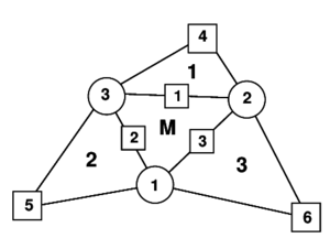
- The geometry of the patch formed by an element and the three adjacent elements is quadratically interpolated from the position of the six nodes in the patch (Fig. 1).
- The membrane strains are assumed to vary linearly within the central triangle and are expressed in terms of the (continuous) values of the deformation gradient at the mid side points of the triangle.
- An assumed constant curvature field within the central triangle is chosen. This is computed in terms of the values of the (continuous) deformation gradient at the mid side points.
Details of the derivation of the EBST element are given below.
3.1 Definition of the Element Geometry and Computation of Membrane Strains
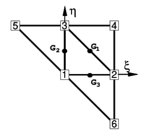
A quadratic approximation of the geometry of the four elements patch is chosen using the position of the six nodes in the patch. It is useful to define the patch in the isoparametric space using the nodal positions given in the Table 1 (see also Fig. 1).
| 1 | 2 | 3 | 4 | 5 | 6 | |
| 0 | 1 | 0 | 1 | -1 | 1 | |
| 0 | 0 | 1 | 1 | 1 | -1 |
The quadratic interpolation is defined by
|
|
(30) |
with ()
|
|
(31) |
This interpolation allows to computing the displacement gradients at selected points in order to use an assumed strain approach. The computation of the gradients is performed at the mid side points of the central element of the patch denoted by , and in Fig. 1. This choice has the following advantages.
|
|
| (a) | (b) |
| Figure 1: (a) Patch of three node triangular elements including the central triangle (M) and three adjacent triangles (1, 2 and 3); (b) Patch of elements in the isoparametric space | |
- Gradients at the three mid side points depend only on the nodes belonging to the two elements adjacent to each side. This can be easily verified by sampling the derivatives of the shape functions at each mid-side point.
- When gradients are computed at the common mid-side point of two adjacent elements, the same values are obtained, as the coordinates of the same four points are used. This in practice means that the gradients at the mid-side points are independent of the element where they are computed. A side-oriented implementation of the finite element will therefore lead to a unique evaluation of the gradients per side.
The Cartesian derivatives of the shape functions are computed at the original configuration by the standard expression
|
|
(32) |
where the Jacobian matrix at the original configuration is
|
|
(33) |
The deformation gradients on the middle surface, associated to an arbitrary spatial Cartesian system and to the material cartesian system defined on the middle surface are related by
|
|
(34) |
The membrane strains within the central triangle are obtained using a linear assumed strain field , i.e.
|
|
(35) |
with
|
|
(36) |
where are the membrane strains computed at the three mid side points ( see Fig. 1). In Eq.(36) , etc.
The gradient at each mid side point is computed from the quadratic interpolation (30):
|
|
(37) |
Substituting Eq.(11) into (36) and using Eq.(9) gives the membrane strain vector as
|
|
(38) |
and the virtual membrane strains as
|
|
(39) |
We note that the gradient at each mid side point depends only on the coordinates of the three nodes of the central triangle and on those of an additional node in the patch, associated to the side where the gradient is computed.
Combining Eqs.(39), (37) and (30) gives
|
|
(40.a) |
with
|
|
(40.b) |
where is the patch displacement vector and is the membrane strain matrix. An explicit form of this matrix is given in [26].
Note that the membrane strains within the EBST element are a function of the displacements of the six patch nodes.
3.2 Computation of Curvatures
We will assume the following constant curvature field within each element
|
|
(41) |
where is the assumed constant curvature field defined by
|
|
(42) |
where is the area (in the original configuration) of the central element in the patch.
Substituting Eq.(42) into (41) and integrating by parts the area integral gives the curvature vector within the element in terms of the following line integral
|
|
(43) |
where are the components (in the local system) of the normals to the element sides in the initial configuration . The integration by parts of Eq.(42) is typical in finite volume methods for computing second derivatives over volumes by line integrals of gradient terms [28,29].
For the definition of the normal vector , the linear interpolation over the central element is used. In this case the tangent plane components are
|
|
(44.a) |
|
|
(44.b) |
From these expressions it is also possible to compute in the original configuration the element area , the outer normals at each side and the side lengths . Equation (44.b) also allows to evaluate the thickness ratio in the deformed configuration and the actual normal .
The numerical evaluation of the line integral in Eq.(43) results in a sum over the integration points at the element boundary which are, in fact, the same points used for evaluating the gradients when computing the membrane strains. As one integration point is used over each side, it is not necessary to distinguish between sides () and integration points (). In this way the curvatures can be computed by
|
|
(45) |
Eq.(45) is now expressed in terms of the shape functions of the 3-noded triangle (which coincide with the area coordinates [4]). Noting the property of the area coordinates
|
|
(46) |
the expression for the curvature can be expressed as
|
|
(47) |
The gradient is evaluated at each side from the quadratic interpolation
|
|
(48) |
This is a basic difference with respect of the computation of the curvature field in the original Basic Shell Triangle (BST) where the gradient at the side mid-point is computed as the average value between the values at two adjacent elements [20,23,26,27].
Note again than at each side the gradients depend only on the positions of the three nodes of the central triangle and of an extra node (), associated precisely to the side () where the gradient is computed.
Direction t in Eq.(47) can be seen as a reference direction. If a different direction than that given by Eq.(44.b) is chosen at an angle with the former, this has an influence of order in the projection. This justifies Eq.(44.b) for the definition of t as a function exclusively of the three nodes of the central triangle, instead of using the 6-node isoparametric interpolation.
The variation of the curvatures can be obtained as
|
|
(49) |
In Eq.(49)
|
|
(50) |
Details of the derivation of the curvature matrix are given in [26,27].
3.3 The EBST1 Element
A simplified and yet very effective version of the EBST element can be obtained by using one point quadrature for the computation of all the element integrals. This element is termed EBST1. Note that this only affects the membrane stiffness matrices and it is equivalent to using a assumed constant membrane strain field defined by an average of the metric tensors computed at each side.
Numerical experiments have shown that both the EBST and the EBST1 elements are free of spurious energy modes.
4 Boundary Conditions
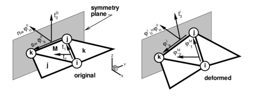
Elements at the domain boundary, where an adjacent element does not exist, deserve a special attention. The treatment of essential boundary conditions associated to translational constraints is straightforward, as they are the natural degrees of freedom of the element. The conditions associated to the normal vector are crucial in the bending formulation. For clamped sides or symmetry planes, the normal vector must be kept fixed (clamped case), or constrained to move in the plane of symmetry (symmetry case). The former case can be seen as a special case of the latter, so we will consider symmetry planes only. This restriction can be imposed through the definition of the tangent plane at the boundary, including the normal to the plane of symmetry that does not change during the process.
The tangent plane at the boundary (mid-side point) is expressed in terms of two orthogonal unit vectors referred to a local-to-the-boundary Cartesian system (see Fig. 2) defined as
|
|
(51) |
where vector is fixed during the process while direction emerges from the intersection of the symmetry plane with the plane defined by the central element (). The plane (gradient) defined by the central element in the selected original convective Cartesian system () is
|
|
(52) |
the intersection line (side ) of this plane with the plane of symmetry can be written in terms of the position of the nodes that define the side ( and ) and the original length of the side , i.e.
|
|
(53) |
That together with the outer normal to the side (resolved in the selected original convective Cartesian system) leads to
|
|
(54) |
where, noting that is the determinant of the gradient, the normal component of the gradient can be approximated by
|
|
(55) |
|
| Figure 2: Local Cartesian system for the treatment of symmetry boundary conditions |
For a simple supported (hinged) side, the problem is not completely defined. The simplest choice is to neglect the contribution to the side rotations from the adjacent element missing in the patch in the evaluation of the curvatures via Eq.(43) [20,23,26]. This is equivalent to assume that the gradient at the side is equal to the gradient in the central element, i.e.
|
|
(56) |
More precise changes can be however introduced to account for the different natural boundary conditions. One may assume that the curvature normal to the side is zero, and consider a contribution of the missing side to introduce this constraint. As the change of curvature parallel to the side is also zero along the hinged side, this obviously leads to zero curvatures in both directions.
We note finally that for the membrane formulation of element EBST, the gradient at the mid-side point of the boundary is assumed equal to the gradient of the main triangle.
More details on the specification of the boundary conditions on the EBST element can be found in [26,27].
5 Explicit Solution Scheme
For simulations including large non-linearities, such as those occuring in sheet metal forming processes involving frictional contact conditions on complex geometries or large instabilities, convergence is difficult to achieve with implicit schemes. In those cases an explicit solution algorithm is typically most advantageous. This scheme provides the solution for dynamic problems and also for quasi-static problems if an adequate damping is chosen.
The dynamic equations of motion to solve are of the form
|
|
(57) |
where is the mass matrix, is the damping matrix and the dot means the time derivative. The solution is performed using the central difference method. To make the method competitive a diagonal (lumped) matrix is typically used and is taken proportional to . As usual, mass lumping is performed by assigning one third of the triangular element mass to each node in the central element.
The explicit solution scheme can be summarized as follows. At each time step where displacements have been computed:
- Compute the internal forces . This follows the steps described in Box 1.
- Compute the accelerations at time
(58) - Compute the velocities at time
(59) - Compute the displacements at time
(60) - Update the shell geometry
- Check frictional contact conditions.
where is the diagonal (lumped) mass matrix.
6 Example 1. Cylindrical Panel under Impulse Loading
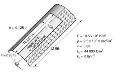
The geometry of the cylinder and the material properties are shown in Fig. 3. A prescribed initial normal velocity of in/sec is applied to the points in the region shown modelling the effect of the detonation of an explosive layer. The panel is assumed to be clamped along all the boundary. One half of the cylinder is discretized only due to symmetry conditions. Three different meshes of , and triangles were used for the analysis. The deformed configurations for are shown for the three meshes in Fig. 3.
The analysis was performed assuming an elastic-perfect plastic material behaviour ( ). A study of the convergence of the solution with the number of thickness layers showed again that four layers suffice to capture accurately the non linear material response [25].
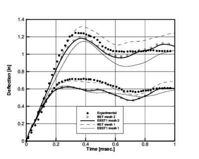
A comparison of the results obtained with the BST and EBST1 elements using the coarse mesh and the finer mesh is shown in Fig. 3 where experimental results reported in [32] have also been plotted for comparison purposes. Good agreement between the numerical and experimental results is obtained. Figs. 4 show the time evolution of the vertical displacement of two reference points along the center line located at in and in, respectively. For the finer mesh results between both elements are almost identical. For the coarse mesh it can been seen that the BST element is more flexible than the EBST1.
Where is the weight of the through-the-thickness integration point. Recall that is the current distance of the layer to the mid-surface and not the original distance. However, for small strain plasticity this distinction is not important. This computation of stresses is exact for an elastic problem.
| ||||||||||||||||
| |

| |
| Figure 3. Cylindrical panel under impulse loading. Geometry and material properties. Deformed meshes for | |
The numerical values of the vertical displacement at the two reference points obtained with the BST and EBST1 elements after a time of 0.4 ms using the mesh are compared in Table 2 with a numerical solution obtained by Stolarski et al. [31] using a curved triangular shell element and the mesh. Experimental results reported in [32] are also given for comparison. It is interesting to note the reasonable agreement of the results for in. and the discrepancy of present and other published numerical solutions with the experimental value for in.
| Vertical displacement (in.) | ||
| element/mesh | in | in |
| BST ( el.) | -1.310 | -0.679 |
| BST ( el.) | -1.181 | -0.587 |
| EBST1 ( el.) | -1.147 | -0.575 |
| EBST1 ( el.) | -1.171 | -0.584 |
| Stolarski et al. [31] | -1.183 | -0.530 |
| Experimental [32] | -1.280 | -0.700 |
|
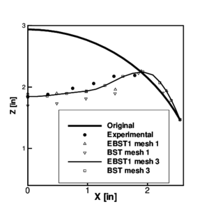
| Figure 5: Cylindrical panel under impulse loading. Final deformation () of the panel at the cross section . Comparison with experimental values |
|
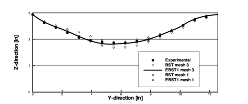
| Figure 6: Cylindrical panel under impulse loading. Final deformation () of the panel at the crown line (). Comparison with experimental values |
The deformed shapes of the transverse section for in. and the longitudinal section for obtained with the both elements for the coarse and the fine meshes after 1ms. are compared with the experimental results in Figs. 5 and 6. Excellent agreement is observed for the fine mesh for both elements.
7 Application to Sheet Metal Forming Problems
The features of tghe EBST1 element make it ideal for analysis of sheet metal stamping processes. A number of examples of simulations of practical problems of this kind are presented. Numerical results have been obtained with the sheet stamping simulation code STAMPACK where the EBST1 element has been implemented [35].
7.1 S-rail Sheet Stamping
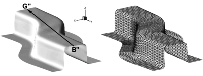
The next problem corresponds to one of the sheet stamping benchmark tests proposed in NUMISHEET'96 [33]. The analysis comprises two parts, namely, simulation of the stamping of a S-rail sheet component and springback computations once the stamping tools are removed. Figure 7 shows the deformed sheet after springback.
|
| Figure 7: Stamping of a S-rail. Final deformation of the sheet after springback obtained in the simulation. The triangular mesh of the deformed sheet is also shown |
The detailed geometry and material data can be found in the proceedings of the conference [33] or in the web [34]. The mesh used for the sheet has 6000 triangles and 3111 points (Fig. 7). The tools are treated as rigid bodies. The meshes used for the sheet and the tools are those provided by the benchmark organizers. The material considered here is a mild steel (IF) with Young Modulus and Poisson ratio . Mises yield criterion was used for plasticity behaviour with non-linear isotropic hardening defined by . A uniform friction of 0.15 was used for all the tools. A low (10kN) blank holder force was considered in this simulation.
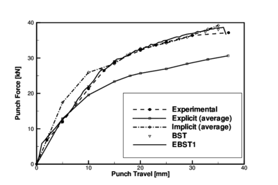
Figure 8 compares the punch force during the stamping stage obtained with both BST and EBST1 elements for the simulation and experimental values. Also for reference the average values of the simulations presented in the conference are included. Explicit and implicit simulations are considered as different curves. There is a remarkable coincidence between the experimental values and the results obtained with both the BST and EBST1 elements.
|
| Figure 8: Stamping of a S-rail. Punch force versus punch travel. Average of explicit and implicit results reported at the benchmark conference are also shown |

|
| Figure 9: Stamping of a S-rail. Z-coordinate along line B–-G after springback. Average of explicit and implicit results reported at the benchmark conference are also shown |
Figure 9 plots the coordinate along line B"–G" after springback. The top surface of the sheet does not remain plane due to some instabilities due to the low blank holder force used. Results obtained with the simulations compare very well with the experimental values.
7.2 Stamping of Industrial Automotive Part
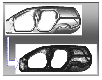
Figure 10 shows the geometry of the lateral panel of a car and the mesh of 457760 EBST1 elements used for the computation. Results of the stamping simulation are shown in Fig. 11. Note that the outpus of the simulation have been translated into graphical plots indicating the quality of the stamping process and the risk of failure in the different zones of the panel. This helps designers to taking decissions on the adequacy of the stamping process and for introducing changes in the design of the stamping tools (dies, punch, blankholders, etc.) and the process parameters if needed.
|
| Figure 10: Lateral panel of an automotive. Finite element mesh of 457760 triangles used for the simulation |
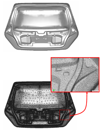
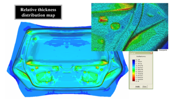
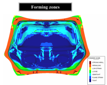
Figure 12 shows the geometry mesh and results of the stamping of a front fender part of an automotive. The initial mesh had 121960 EBST1 elements. Adaptive mesh refinement was used along the simulation process leading to a final mesh of 389870 elements. Finally, Figs. 13 and 14 show the same type of information for the stamping of a car tail gate. The initial and final meshes (after adaptive mesh refinement) had 186528 and 489560 EBST1 elements, respectively. The simulation results are displayed in both problems with an “engineering insight” in order to help the design and manufacturing of the stamping tools and the definition of the stamping process as previously mentioned.

|

|

|

|
| Figure 11: Lateral panel of a car. Results of the stamping analysis | |

|
| Figure 12: Front fender. Results of the stamping analysis using an initial mesh of 121960 EBST1 elements. The final adapted mesh had 389870 elements |
|
| Figure 13: Car tail gate. Geometry and final adapted mesh of 489560 EBST1 elements used for the stamping simulation |
| |
| |
| Figure 14: Car tail gate. Map of relative thickness distribution and forming zones on the stamped part | |
8 Concluding Remarks
An enhanced rotation-free shell triangle (termed EBST) is obtained by using a quadratic interpolation of the geometry in terms of the six nodes belonging to the four elements patch associated to each triangle. This allows to computing an assumed constant curvature field and an assumed linear membrane strain field which improves the in-plane behaviour of the original element. A simple and economic version of the element using a single integration point has been presented. The efficiency of the rotation-free shell triangle has been demonstrated in examples of application including the analysis of a cylinder under impulse loading and practical sheet stamping problems.
The enhanced rotation-free basic shell triangle element with a single integration point (the EBST1 element) is an excellent candidate for solving practical sheet metal stamping problems and other non linear shell problems in engineering involving complex geometry, dynamics, material and geometrical non linearities and frictional contact conditions.
ACKNOWLEDGEMENTS
The support of the company QUANTECH (www.quantech.es) providing the code STAMPACK [35] is gratefully acknowledged.
This research was partially supported by project SEDUREC of the Consolider Programme of the Ministerio de Educación y Ciencia of Spain.
References
[1] Oñate E (1994) A review of some finite element families for thick and thin plate and shell analysis. Publication CIMNE N. 53, May
[2] Flores FG, Oñate E, Zárate F (1995) New assumed strain triangles for non-linear shell analysis. Computational Mechanics 17:107–114
[3] Argyris JH, Papadrakakis M, Apostolopoulou C, Koutsourelakis S (2000) The TRIC element. Theoretical and numerical investigation. Comput Meth Appl Mech Engrg 182:217–245
[4] Zienkiewicz OC, Taylor RL (2005) The finite element method. Solid Mechanics. Vol II, Elsevier
[5] Stolarski H, Belytschko T, Lee S-H (1995) A review of shell finite elements and corotational theories. Computational Mechanics Advances vol. 2 (2), North-Holland
[6] Ramm E, Wall WA (2002) Shells in advanced computational environment. In V World Congress on Computational Mechanics, Eberhardsteiner J, Mang H, Rammerstorfer F (eds), Vienna, Austria, July 7–12. http://wccm.tuwien.ac.at.
[7] Bushnell D, Almroth BO (1971) Finite difference energy method for non linear shell analysis. J Computers and Structures 1:361
[8] Timoshenko SP (1971) Theory of Plates and Shells, McGraw Hill, New York
[9] Ugural AC (1981) Stresses in Plates and Shells, McGraw Hill, New York
[10] Nay RA, Utku S (1972) An alternative to the finite element method. Variational Methods Eng vol. 1
[11] Hampshire JK, Topping BHV, Chan HC (1992) Three node triangular elements with one degree of freedom per node. Engng Comput 9:49–62
[12] Phaal R, Calladine CR (1992) A simple class of finite elements for plate and shell problems. I: Elements for beams and thin plates. Int J Num Meth Engng 35:955–977
[13] Phaal R, Calladine CR (1992) A simple class of finite elements for plate and shell problems. II: An element for thin shells with only translational degrees of freedom. Int J Num Meth Engng 35:979–996
[14] Oñate E, Cervera M (1993) Derivation of thin plate bending elements with one degree of freedom per node. Engineering Computations 10:553–561
[15] Brunet M, Sabourin F (1994) Prediction of necking and wrinkles with a simplified shell element in sheet forming. Int Conf of Metal Forming Simulation in Industry II:27–48, Kröplin B (ed)
[16] Rio G, Tathi B, Laurent H (1994) A new efficient finite element model of shell with only three degrees of freedom per node. Applications to industrial deep drawing test. In Recent Developments in Sheet Metal Forming Technology, Barata Marques MJM (ed), 18th IDDRG Biennial Congress, Lisbon
[17] Rojek J, Oñate E (1998) Sheet springback analysis using a simple shell triangle with translational degrees of freedom only. Int J of Forming Processes 1(3):275–296
[18] Rojek J, Oñate E, Postek E (1998) Application of explicit FE codes to simulation of sheet and bulk forming processes. J of Materials Processing Technology 80-81:620–627
[19] Jovicevic J, Oñate E (1999) Analysis of beams and shells using a rotation-free finite element-finite volume formulation, Monograph 43, CIMNE, Barcelona
[20] Oñate E, Zárate F (2000) Rotation-free plate and shell triangles. Int J Num Meth Engng 47:557–603
[21] Cirak F, Ortiz M (2000) Subdivision surfaces: A new paradigm for thin-shell finite element analysis. Int J Num Meths in Engng 47:2039-2072
[22] Cirak F, Ortiz M (2001) Fully -conforming subdivision elements for finite deformations thin-shell analysis. Int J Num Meths in Engng 51:813-833
[23] Flores FG, Oñate E (2001) A basic thin shell triangle with only translational DOFs for large strain plasticity. Int J Num Meths in Engng 51:57–83
[24] Engel G, Garikipati K, Hughes TJR, Larson MG, Mazzei L, Taylor RL (2002). Continuous/discontinuous finite element approximation of fourth-order elliptic problems in structural and continuum mechanics with applications to thin beams and plates, and strain gradient elasticity. Comput Methods Appl Mech Engrg 191:3669–3750
[25] Oñate E, Cendoya P, Miquel J (2002) Non linear explicit dynamic analysis of shells using the BST rotation-free triangle. Engineering Computations 19(6):662–706
[26] Flores FG, Oñate E (2005) Improvements in the membrane behaviour of the three node rotation-free BST shell triangle using an assumed strain approach. Comput Meth Appl Mech Engng 194(6-8):907–932
[27] Oñate E, Flores FG (2005) Advances in the formulation of the rotation-free basic shell triangle. Comput Meth Appl Mech Engng 194(21–24):2406–2443
[28] Zienkiewicz OC, Oñate E (1991) Finite Elements vs. Finite Volumes. Is there really a choice?. Nonlinear Computational Mechanics. State of the Art. Wriggers P, Wagner R (eds), Springer Verlag, Heidelberg
[29] Oñate E, Cervera M, Zienkiewicz OC (1994) A finite volume format for structural mechanics. Int J Num Meth Engng 37:181–201
[30] Hill R (1948) A Theory of the Yielding and Plastic Flow of Anisotropic Metals. Proc Royal Society London A193:281
[31] Stolarski H, Belytschko T, Carpenter N (1984) A simple triangular curved shell element. Eng Comput 1:210–218
[32] Balmer HA, Witmer EA (1964) Theoretical experimental correlation of large dynamic and permanent deformation of impulsively loaded simple structures. Air force flight Dynamic Lab Rep FDQ-TDR-64-108, Wright-Patterson AFB, Ohio, USA
[33] NUMISHEET'96 Third International Conference and Workshop on Numerical Simulation of 3D Sheet Forming Processes, Lee EH, Kinzel GL, Wagoner RH (eds), Dearbon-Michigan, USA, 1996
[34] http://rclsgi.eng.ohio-state.edu/%Elee-j-k/numisheet96/
[35] STAMPACK. A General Finite Element System for Sheet Stamping and Forming Problems, Quantech ATZ, Barcelona, Spain, 2007. (www.quantech.es)
Document information
Published on 01/01/2007
DOI: 10.1007/978-1-4020-6577-4_14
Licence: CC BY-NC-SA license
Share this document
claim authorship
Are you one of the authors of this document?

