Abstract
A new irradiance adjustment system for the light source named “Programmable Reference cell system for Irradiance adjustment by Spectral Measurement (PRISM)” has been developed for photovoltaics evaluation. It can be applied for various kinds of solar cells and illumination conditions without the preparation of conventional reference cells. This system consists of a device for absolute spectral responsivity measurements, that is, the spectral responsivity unit, and a device for irradiance adjustment of the light source, that is, the spectral reference cell. First, the short circuit current of the target solar cell (Iref) is calculated by convolution of the absolute spectral responsivity with the spectral irradiance under STC (AM1.5 G, 1 kW/m2, 25°C) as defined in IEC 60904-3. The spectral irradiance of the light source is then adjusted for I–V measurements so that the short-circuit current of the spectral reference cell (Ical), calculated by convolution of the absolute spectral responsivity with the spectral irradiance of the light source, agrees with Iref. The difference between Iref and the short circuit current, as determined at an internationally recognized test center under STC, was within ±2% for crystalline silicon solar cells and ±3% for organic solar cells. The difference between Ical and the short-circuit current measured under a solar simulator or LED in which the irradiance was adjusted by this system was within ±4% when the irradiance was higher than 4 W/m2.
Introduction
Crystalline silicon solar cells are used in the largest quantities for solar energy systems, however, their high manufacturing cost and heavy weight prevent the widespread use of solar energy. To address this problem, various types of solar cells, for example, compound semiconductors, organic thin films, dye-sensitized, and perovskite [1] solar cells are under investigation by various groups with some of them being already commercialized.
Further development of materials and cell structure as well as appropriate evaluation methods for cell functions will be required to gauge and improve the overall performance of solar cells. International standards for the evaluation of silicon solar cells have been established by the IEC as the 60904 Series, however, they define only test methods under standard test conditions (STC) although, when compared to crystalline silicon-based cells, higher performance can be expected for some types of solar cells under weak irradiation such as faint morning, evening, indoor or oblique light [2]. Moreover, new types of solar cells sometimes have characteristics different from that of silicon solar cells such as nonlinearity between the current and light intensity, a light soaking effect, and slow response time, which are not taken into consideration in the IEC 60904 standards [3, 4].
The reference cell method is widely used for irradiance adjustment of a solar simulator [5] and this method requires the preparation of a reference cell as defined in IEC 60904-2, 4 [6, 7]. However, preparation of a reference cell with a spectral response that matches the solar cell being tested is difficult and extremely time-consuming [8, 9], especially, for such unstable cells as dye-sensitized solar cells (DSCs). It is necessary to prepare a filtered reference cell with its relative spectral responsivity coincident with that of the organic PV to be tested, which should then be calibrated at a recognized institute. However, this may take several months to 1 year since the filtered reference cell must also be checked for long-term stability. In this work, we have developed a new irradiance adjustment system for the light source named, “Programmable Reference cell system for Irradiance adjustment by Spectral Measurement (PRISM)” which can be applied for any type of solar cell under various illumination conditions without the use of conventional reference cells [10-19]. In this work, the performance of this system has been investigated for various solar cells and illumination conditions.
Principle
Basic procedures
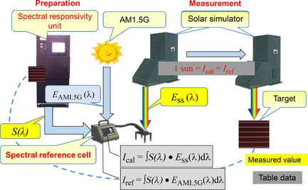
The PRISM system consists of a device for absolute spectral responsivity measurements (spectral responsivity unit: SK-1150) which meets IEC 60904-4, 8 standards [7, 8] and a device for light source irradiance adjustment (spectral reference cell: SRC-1100), as shown in Figure 1. The basic procedures for measurements at STC (AM1.5G, 1 kW/m2, 25°C) are as follows:
|
|
|
Figure 1. Schematic diagram of the PRISM system. PRISM, Programmable Reference cell system for Irradiance adjustment by Spectral Measurement. |
- Spectral responsivity of the target solar cell (S(λ)) is measured with the SK-1150 unit.
- The short-circuit current of the target solar cell (Iref) is calculated by convolution of the absolute spectral responsivity S(λ) with the spectral irradiance at STC (AM1.5G, 1 kW/m2, 25°C) as defined in IEC 60904-3 (EAM1.5G(λ)) [9], using the SRC-1100 reference cell device, as follows:
(1) - The spectral irradiance of the solar simulator (Ess(λ)) is adjusted until the short-circuit current of SRC-1100 (Ical), calculated from equation (2), agrees with Iref.
(2) - Current-voltage characteristics (I–V curves) of the target cell are measured by a solar simulator, the irradiance of which is adjusted through the above procedures.
Measurement of nonlinear cells
The short-circuit current of some types of organic solar cells is not always proportional to the irradiance. In this case, equation (1) should be modified to
|
|
(3) |
where S(λ, Eb) indicates the spectral responsivity which may vary with the irradiance (Eb = ∫Ess(λ) dλ). However, it is difficult to measure S(λ, Eb) by commonly available devices since they are not able to regulate the irradiance level to desired values. To address this problem, we have developed the PRISM system which uses the differential spectral responsivity (DSR) method developed by Physikalisch-Technische Bundesanstalt (PTB) and defined in IEC 60904-4, 8 and ISO 15387 [7, 8, 20, 21].
Measurements under various illumination conditions
The PRISM system employing the DSR method can be applied for measurements under any illumination conditions. Thus, the short-circuit current (Isc) for any solar cell under any illumination conditions can be calculated as follows:
|
|
(4) |
where E(λ) is the spectral irradiation from any light source.
Key Devices for the PRISM System
Spectral responsivity unit (SK-1150)
The SK-1150 unit has been constructed to simultaneously illuminate the bias light irradiance (Eb) and monochromatic light irradiance onto a solar cell. Both lights are combined in the lens and irradiated on the solar cell. The irradiation unit consists of a halogen lamp, Xenon lamp, grating and chopping units, and light monitors to compensate for any instability of the lamps. The current measurement unit consists of a source meter and lock-in amplifier, both of which are controlled by a computer.
The absolute spectral responsivity of this device is measured using a standard detector calibrated at an internationally recognized test center. Differential spectral responsivity is measured at various irradiances of bias light and S(λ, Eb) is then automatically calculated by a computer [7, 8, 20, 21].
When the current response to the applied light irradiation is slow, for example, in the case of dye-sensitized solar cells (DSCs), the chopping frequency of the monochromatic light should be low enough to obtain a steady-state current. Aoki et al. have reported that S(λ, Eb) decreases as the chopping frequency is increased [3], indicating that it should be lower than 3.3 Hz to obtain accurate data under 1 sun bias light irradiation. However, spectral responsivity measurement using the lock-in amplifier is unsuitable for low-frequency measurements since long and repetitive measurements are required to obtain accurate data, for example, several hours at 0.3 Hz.
To address this problem, this system has two methods to determine S(λ, Eb), that is, the selective amplification of the current caused by monochromatic light irradiation using the lock-in amplifier and the calculation of the difference between currents measured when the shutter of the monochromatic light is open and closed using the DC current amplifier. The latter method is similar to the AC-a method reported by Guo et al. [22], and requires less measuring time because the lock-in amplifier method takes a chopping frequency of 10 cycles.
Spectral reference cell device (SRC-1100)
The SRC-1100 device consists of a spectroradiometer for spectral irradiance measurement of the light source, an optical receiver and computer. With this device, irradiance adjustment of the solar simulator can be performed according to the procedures described in the 'Basic procedures' section.
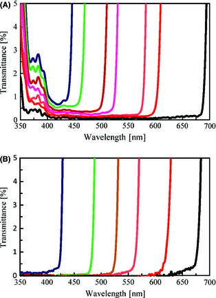
The spectroradiometer equipped in this device has a high sensitivity image sensor of back-thinned CCD to measure very low irradiance, such as indoor light, as compared to AM 1.5 G (1 kW/m2). Additionally, it has a unique optical system to reduce stray light which causes inaccurate readings. Figure 2 shows the transmittance level of the stray light measured in accordance with JIS Z8724 (Japan Industrial Standards, Methods of measurement Light-source colour) [23].
|
|
|
Figure 2. Transmittance level of stray light determined for: (A) a conventional spectroradiometer; and (B) the spectroradiometer equipped in this device. |
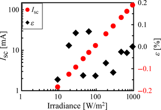
The irradiance measured by the spectroradiometer should have a linear relationship with the short-circuit current of the linear cell under a wide irradiation range, for example, from indoor light to 1 sun. The short-circuit current (Isc) and linearity error (ε) were determined for the linear cell (Konica Minolta, AK-200) by the spectroradiometer and were plotted against the Irradiance (), as shown in Figure 3 (Konica Minolta is hereafter referred to as KM). The ε was calculated as follows:
|
|
(5) |
where
|
|
|
Figure 3. Short-circuit current (Isc) and linearity error (ε) of SRC-1100 plotted against the irradiance. SRC, spectral reference cell |
The linearity error (ε) was within ±0.2% at an irradiation range of 10–1000 W/m2, as shown in Figure 3.
The sensitivity of a spectroradiometer is known to change with time [24] by vibration and degradation of its optical components, etc., while instrument-to-instrument variations also exist [25, 26]. No change in the relative spectral responsivity of the standard lamp was measured, but about a 5% decrease in irradiance was measured by the spectroradiometer in 100 days.
The SRC-1100 is first calibrated at the manufacturing factory using a standard lamp traceable to that of a recognized national institute; however, as mentioned above, the measured value changes with time. To reduce these effects, SRC-1100 has a user calibration function to resolve changes before measurements. This apparatus has a stable reference cell (KM, AK-200) with absolute spectral responsivity (Src(λ)) traceable to the calibrated value of a national institute. First, the reference cell is placed under the light source and the short-circuit current (Imes_rc) is measured. Next, the irradiance (Ess(λ)) is measured and the absolute irradiance calculated by multiplying (Ess(λ)) by a correcting factor (K = Imes_rc/Ess(λ)·Src(λ)d λ). If the sensitivity of SRC-1100 shows no change with time, K equals 1.
Intercomparison of Short Circuit Currents Among Calibration Centers
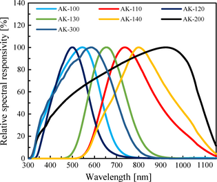
Intercomparisons of the short circuit currents were carried out at three internationally recognized calibration centers, that is, the National Institute of Advanced Industrial Science & Technology (AIST), National Renewable Energy Laboratory (NREL), and PTB [27] for multiple reference cells (KM, AK series) to investigate variations in their measured values. Table 1 and Figure 4 show the type of cells in the AK series and their relative spectral responsivities, respectively. Table 1 also summarizes the centroid wavelengths (Wc) of the reference cells for the AK series which were calculated by equation (7). Here, it should be noted that Wc is the representative wavelength of the spectral responsivity at STC.
| Reference cells | Type | Centroid wavelength |
|---|---|---|
| ||
| AK-100 | Amorphous Si-type | 521 nm |
| AK-110 | Microcrystalline Si-type | 791 nm |
| AK-120 | Top layer of triple junction | 499 nm |
| AK-130 | Middle layer of triple junction | 664 nm |
| AK-140 | Bottom layer of triple junction | 831 nm |
| AK-200 | Crystalline Si-type | 772 nm |
| AK-300 | DSC N719 type | 553 nm |
|
|
|
Figure 4. Relative spectral responsivities of the reference cells. |
|
|
(6) |
The centroid wavelength can be employed as the index of each reference cell to indicate the representative spectral responsivity, thus, allowing comparisons of multiple reference cells. For example, the centroid wavelengths of AK-100 (Amorphous Si-type cell), AK-200 (Crystalline Si-type cell), and AK-110 (Microcrystalline Si-type cell) are 521 nm, 772 nm, and 791 nm, respectively. First, the short-circuit current of each cell was measured at KM, then the secondary reference solar cell was calibrated at AIST. The cells were then sent to PTB and NREL, and variations in the short circuit currents among the three recognized calibration centers were investigated. The difference in short-circuit current with the elapse of time was found to be within ±0.3% in a 2-year period from 2011 to 2013.
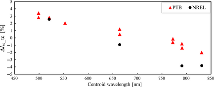
Figure 5 shows the differences in the short-circuit current among the test centers (ΔIsc_tc) plotted against the centroid wavelength of the spectral responsivity (Wc) for each cell. The ΔIsc_tc were calculated as follows:
|
|
(7) |
|
|
|
Figure 5. Difference in the short-circuit current among the calibration centers plotted against the centroid wavelength. |
where Isc_tc is the short-circuit current determined at PTB or NREL, and Isc_km is that determined at KM with the secondary reference solar cell calibrated at AIST. Dirnberger et al. have reported intercomparison of the short-circuit current for crystal Si-type and amorphous Si-type modules performed by the Fraunhofer Institute for Solar Energy Systems (ISE), European Solar Test Installation (ESTI of the European Commission, Joint Research Centre, Institute for Energy and Transport, Renewable Energy Unit), and the NREL and AIST [28]. They reported that deviations in the short-circuit current of the crystal Si-type module was 2% (−1.1 to 0.9%), but that of the amorphous Si-type module was −2.9% for the data measured at AIST and 1.6% for that measured at NREL. The value from NREL was found to be 4.5% higher than that of AIST. In this paper, deviation of the short-circuit current was 0.9% for crystalline Si-type cells and 2.8% (0–2.8%) for amorphous Si-type cells. Thus, the value from NREL was 2.8% higher than that of AIST. The tendency for greater deviation of the short-circuit current for amorphous Si-type cells than crystalline Si-type cells was also recognized in this paper. As shown in Figure 5, the ΔIsc_tc values of cells having Wc in the long wavelength range were negative and those of cells having Wc in the short wavelength range were positive, although the reason for this tendency is not yet clear at present. Further investigation is required to analyze this tendency. On the other hand, intercomparison results of this paper were found to be reasonable since the total estimated uncertainty to determine the short-circuit current was 3.8%. The estimated uncertainty of a recognized calibration center was within 1% and within 1.8% at KM. Taking these results into consideration, the maximum deviation under STC for the PRISM system was set within 4%, equivalent to the error range allowance in the above results.
Experimental
Performance verification of SK-1150
The performance of the SK-1150 unit was verified by comparing the short circuit currents of the solar cells at STC with those determined at a recognized test center. That is, the difference in the short-circuit current (ΔIsc_stc) between that determined by SK-1150 (Iref) and that determined at a test center (Iref_tc) was calculated as follows:
|
|
(8) |
Performance verification of SRC-1100
Performance of the SRC-1100 device was verified by comparing the short circuit currents calculated from equation (2) (Ical) with those measured under a solar simulator (Imes) or LED. The difference in the short-circuit current between Ical and Imes (ΔIsc) was calculated as follows:
|
|
(9) |
The three types of solar simulators and LED light source used in the evaluations are shown in Table 2. The solar simulators were all class AAA but with differing spectral irradiance distributions in order to examine the spectral irradiance dependence. The source meters were Agilent B2901A, ADCMT 6242, and Advantest R6246.
| Type | Manufacturer | Irradiance level | Target cells |
|---|---|---|---|
| |||
| XES-40S | SAN-EI ELECTRIC | 10–1000 W/m2 | Reference cells/Nonlinear cells/DSC-NIMS/OPV |
| 94023A | NewPort | 1000 W/m2 | Reference cells |
| YSS-T150A | YamashitaDenso | 10–1000 W/m2 | DSC-A/DSC-B |
| LED | Imac | 10–300 W/m2 | Reference cells/Nonlinear cells/DSC-NIMS/OPV |
Spectral responsivity measurements of DSC
Two different types of dye-sensitized solar cells (DSCs) were tested: one cell containing 3-Methoxypropionitrile (MPN) as the solvent for the electrolyte (DSC-A) and the other containing an ionic liquid electrolyte (DSC-B). The viscosity of the ionic liquid electrolyte was about 30 times higher than that containing MPN at 20°C. A mesoscopic TiO2 semiconductor electrode sensitized by cis-RuLL'-(SCN)2 (L = 2,2′-bipyridyl-4,4′-dicarboxylic acid, L' = 4,4′-dinonyl-2,2′-bipyridyl) (Z907) dye was used for both cells. The active area for each cell was 0.196 cm2 [3]. Additionally, DSCs supplied by the National Institute for Materials Science (DSC-NIMS-1 and DSC-NIMS-2) were also used. For these DSCs, a carbazole dye with hexyl-substituted oligothiophenes, MK-2 (Soken Chemical & Engineering Co., Ltd., Tokyo, Japan), was used as a sensitizer. An ionic liquid based on imidazolium iodide was used as the electrolyte. Transparent nanocrystalline TiO2 films were prepared as follows: The films were formed by a screen printing method, that is, TiO2 paste (Nanoxide-20N, Nikki Syokubai Kasei) was screen-printed onto a transparent conducting oxide (TCO) glass substrate (F-doped SnO2, sheet resistance 10 ohm/cm2, Nippon Sheet Glass), followed by sintering at 500°C for 60 min in air.
Before measurements, the cells were stabilized by light soaking at the same irradiance as that for the bias light. In the case of DSC-NIMS-1, the short-circuit current reached a steady-state value in about 96 h during light soaking at an irradiance of 1 sun. The cell was kept in the dark for about 100 h after 96 h light soaking, and then irradiated again under the same conditions. The short-circuit current reached a steady-state value immediately after irradiation.
The absolute spectral responsivity (S(λ)) was measured by SK-1150 at 25°C with bias light irradiance levels between 0 to 1.2 sun. Wavelength resolution was 10 nm and the chopping frequency of the monochromatic light was set low enough to obtain a steady-state current.
I–V measurements
Solar cell efficiencies are, at present, measured at STC, however, by adjusting the light irradiance using the PRISM method, I–V characteristics were measured under various irradiances with a solar simulator (San-ei Electric XES-40S) and LED light source (Imac). The voltage sweep rates were set so that an I–V curve determined by the forward scan (from short circuit to open circuit) agreed with that by reverse scan. The solar cell efficiency (η) and fill factor (FF) were calculated as follows:
|
|
(10) |
|
|
(11) |
where Voc, Jsc, Prad, and Pmax represent the open circuit voltage, short circuit current density, incident light intensity and maximum power, respectively.
Results and Discussions
Performance of the SK-1150 unit
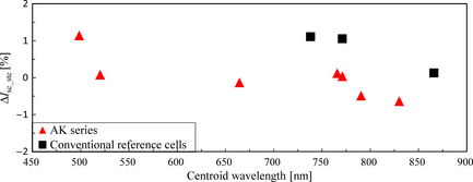
Figure 6 shows the differences in the short-circuit current (ΔIsc_stc) between that determined by SK-1150 and that determined at a recognized calibration center for linear reference cells at STC plotted against the centroid wavelength (Wc). As shown in Figure 6, the ΔIsc_stc was within ±1.5%.
|
|
|
Figure 6. Difference in the short-circuit current (ΔIsc_stc) between that determined by the PRISM SK-1150 unit and that determined at a calibration center for linear cells under STC plotted against the centroid wavelength of the spectral responsivity (Wc). PRISM, Programmable Reference cell system for Irradiance adjustment by Spectral Measurement; SK-1150, Spectral responsivity unit; STC, standard test conditions. |
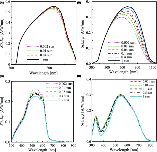
The spectral responsivity (S(λ, Eb)) determined for the two nonlinear cells (cells A and B), an organic thin film solar cell (OPV), and a dye-sensitized solar cell containing an ionic liquid electrolyte (DSC-B) are shown in Figure 7. The ΔIsc_stc values determined for these cells are shown in Tables 3 and 4. Nonlinear cells are those in which the spectral responsivities change with the bias light intensity [8]. The S(λ, Eb) of both cells increased with an increase in the bias light intensity in a wavelength range over 500 nm, while the degree of increase was larger for cell B. The ΔIsc_stc was 0.1% for cell A and −0.3% for cell B.
| Cell | ΔIsc_stc (%) |
|---|---|
| A | 0.1 |
| B | −0.3 |
| Cell | ΔIsc_stc (%) |
|---|---|
| |
| OPV | −1.1 |
| DSC-B | −2.6 |
|
|
|
Figure 7. Spectral responsivity (S(λ, Eb)) determined for two nonlinear cells (cells A and B), OPV and DSC-B: (A) Cell A, (B) Cell B, (C) OPV, (D) DSC-B. DSC, dye-sensitized solar cells; OPV, organic thin film solar cell. |
Unlike the nonlinear cells, the S(λ, Eb) of the OPV and DSC-B decreased with an increase in the bias light intensity at wavelengths under 650 nm. Similar results have been reported for DSCs by Hara et al. [29], Guo et al. [22] and Aoki et al. [3]. Hara et al. have suggested that this decrease in the spectral responsivity may be related to light absorption in the wavelength range of 400–500 nm caused by accumulation in the vicinity of the electrode due to oxidation of I− and accelerated by bias light irradiation. Table 4 shows that ΔIsc_stc was −1.1% for the OPV and −2.6% for DSC-B.
The maximum deviation under STC for the PRISM system was set within 4%, as mentioned before. The ΔIsc_stc values determined for the linear and nonlinear reference cells, OPV, and DSC were found to be within this maximum deviation.
Performance of the SRC-1100 device
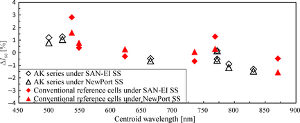
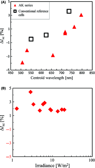
First, the differences in the short-circuit current (ΔIsc) between Ical and Imes calculated from equation (10) for the linear reference cells under STC were determined, and the results are shown in Figure 8. Two sets of the SRC-1100 device with different solar simulators (San-ei Electric XES-40S and Newport Corp 94023A) were employed. As shown in Figure 8, ΔIsc was within ±3%, which is within the maximum deviation set for the PRISM system.
|
|
|
Figure 8. Difference in the short-circuit current (ΔIsc) between Ical and Imes calculated from equation (10) for the reference cells (Konica Minolta AK series and conventional reference cells made by other companies) under the solar simulators. |
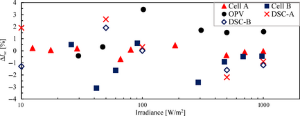
Next, the ΔIsc of the nonlinear cells, OPV, and DSCs were determined by changing the irradiance. A San-ei Electric XES-40S solar simulator was used for the nonlinear cells and the OPV, and a Yamashita Denso YSS-T150A simulator was used for the DSCs. Figure 9 shows the ΔIsc determined for these cells. The ΔIsc of the nonlinear cells and the OPV was within ±4% and larger for cell B than cell A. The ΔIsc of the DSCs was within ±3% and larger for DSC-A than DSC-B. The ΔIsc determined for DSC-NIMS-1 and DSC-NIMS-2 were within ±4% under the solar simulator with an irradiance range of 10–1000 W/m2. These results show that the ΔIsc is within the maximum deviation set for the PRISM system even under such low irradiance as 10 W/m2.
|
|
|
Figure 9. ΔIsc determined for two nonlinear cells (cells A and B), OPV, DSC-A and DSC-B under the solar simulator. OPV, organic thin film solar cell; DSC, dye-sensitized solar cells. |
The ΔIsc under LED was also investigated. The ΔIsc for the reference cells under LED with an irradiance of 3.97 W/m2 and that determined for nonlinear cells by changing the irradiance of LED are shown in Figure 10. The ΔIsc of the reference cells was within ±4% which is within the maximum deviation set for the PRISM system. The ΔIsc of the nonlinear cells was within ±3% when the irradiance was higher than 4 W/m2. These results show that the PRISM system is applicable not only to sunlight but also LED light when the irradiance is higher than 4 W/m2. Since an increase in ΔIsc under low irradiance may result from the S/N ratio of the equipment, improvement in the equipment components will also need to be implemented for less uncertainty.
|
|
|
Figure 10. (A) ΔIsc determined for the reference cells under LED with an irradiance of 3.97 W/m2 and (B) ΔIsc determined for nonlinear cells by changing the irradiance of LED. |
I–V characteristic measurements
Changes in solar cell efficiency and open circuit voltage upon irradiance with a light source
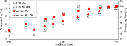
The PRISM system was applied to determine changes in the solar cell efficiency (η) and open circuit voltage (Voc) upon irradiance with a solar simulator. The target cells were DSC-NIMS-2 and AK-100, and the solar simulator was a San-ei Electric XES-40S. Figure 11 shows the changes in η and Voc upon irradiance with the solar simulator. The η of the DSC increased with an increase in irradiance at a range from 0.01 to about 0.2 sun, then gradually decreased, whereas the Voc monotonously increased with an increase in irradiance. Contrarily, in the case of AK-100, both η and Voc decreased with a monotonous decrease in irradiance. The rates of decrease in η and Voc for the DSC with a decrease in irradiance were less than of those for AK-100.
|
|
|
Figure 11. Changes in the solar cell efficiency (η) and open circuit voltage (Voc) determined for DSC-NIMS-2 and AK-100 upon irradiance with a solar simulator. DSC-NIMS-2, dye-sensitized solar cells-National Institute for Materials Science. |
Determination of solar cell efficiency under weak LED irradiation
The results shown in Figure 11 suggest that, under weak irradiation, higher performance can be expected for some types of solar cells when compared to crystalline solar cells. For example, organic solar cells can be specifically considered for indoor use due to their flexibility, lightness and high designability, however, a standard method to verify their performance has yet to be established.
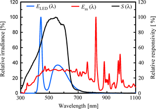
The PRISM system was also applied to determine the photoelectric conversion efficiencies of OPV and DSC under LED which exhibits irradiance similar to indoor light. Table 5 shows the performance of the OPV under the solar simulator and LED. The solar cell efficiency (η) under LED was more than twice that obtained under 1 sun. Figure 12 shows the relationship between the spectral responsivity of the OPV and spectral irradiances of the light sources. As shown in Figure 12, the light emission wavelength region of the LED was approximately within the absorption wavelength region of the OPV, however, the wavelength region of natural sunlight is much wider than the absorption wavelength region of the OPV. This may explain why the η obtained under LED was greater than that obtained under 1 sun. The performance of DSC-NIMS-1 under the solar simulator and LED are shown in Table 6. As with the OPV, the η under LED was larger than that under 1 sun.
| Light source | Jsc mA/cm2 | Voc V | Pmax W/m2 | Irradiance W/m2 | η % |
|---|---|---|---|---|---|
| |||||
| Solar simulator | 7.05 | 0.46 | 18.0 | 1000 (1 sun) | 1.8 |
| LED | 0.0815 | 0.34 | 0.176 | 4.57 | 3.9 |
| Light source | Jsc mA/cm2 | Voc V | Pmax W/m2 | Irradiance W/m2 | η % |
|---|---|---|---|---|---|
| |||||
| Solar simulator | 13.8 | 0.60 | 61.4 | 1000 (1 sun) | 6.1 |
| LED | 0.120 | 0.47 | 0.345 | 4.10 | 8.4 |
|
|
|
Figure 12. Relationship between the spectral responsivity of the OPV (S(λ)) and spectral irradiance of the light sources ((E_LED(λ) for LED, E_ss(λ) for the San-ei Electric XES-40S (1 sun)). OPV, organic thin film solar cell. |
Conclusions
The newly developed PRISM system, consisting of a SK-1150 unit which measures the absolute spectral responsivity of a target cell and the SRC-1100 device which stores this data along with the reference spectral irradiance and that of the light source in order to adjust its irradiance, was found to be applicable for any type of solar cell under various illumination conditions. Significantly, the SRC-1100 acts as the reference cell, allowing comparison studies without the preparation of conventional reference cells as defined in IEC 60904-2, 4, thus, dramatically reducing the preparation time for I–V characterization measurements of a newly developed cell. The PRISM system makes it unnecessary to prepare a filtered reference cell and then confirm its stability over months. It is thus possible to avoid these tedious and lengthy procedures before measurement of organic solar cell performance. This is because the data of the absolute spectral responsivity itself serves the same function as a reference cell.
Regarding accuracy, differences in the short-circuit current between that determined by the SK-1150 and at a recognized test center under STC were within ±2% for the filtered reference cells and nonlinear cells, and within ±3% for organic solar cells. The typical calibration uncertainty at a secondary or working calibration institute is around 2%, meaning that SK-1150′s accuracy is comparable to calibrations at these facilities. Upon irradiance adjustment with this PRISM system, the difference in the short-circuit current between that obtained by convolution of the absolute spectral responsivity with the spectral irradiance of a solar simulator or LED and that measured with the adjusted light source was within ±3% under STC and ±4% under various illumination conditions when the irradiance was higher than 4 W/m2.
In the case of calibration of the light irradiance under STC conditions using a conventional method with a reference cell, the adjustment accuracy was also comparable the present PRISM method. However, in the case of the calibration of various kinds of light sources with even low irradiance, the PRISM system enables a traceable measurement method for irradiance adjustment which had so far been difficult due to the lack of a suitable reference cell with a certified value. This system will be particularly useful for the preparation and I–V measurement of nonlinear organic solar cells which have a variety of spectral responsivities.
Acknowledgments
The authors express their sincere appreciation to the Japan Science and Technology Agency (JST) Development of Advanced Measurement and Analysis Systems funding program for their financial support and encouragement. They thank Dr M. Yanagida of the National Institute for Materials Science for supplying the stable DSC cells used in this work. Sincere gratitude is also extended to the National Institute of Advanced Industrial Science & Technology (AIST, Japan), National Renewable Energy Laboratory (NREL, USA), and Physikalisch Technische Bundesanstalt (PTB, Germany) for their useful advice on the traceable calibration method.
Conflict of Interest
None declared.
References
- Lee, M. M., J. Teuscher, T. Miyasaka, T. N. Murakami, and H. J. Snaith. 2012. Efficient hybrid solar cells based on meso-superstructured organometal halide perovskites. Science338:643–647. doi: 10.1126/science.
- Ito, S., H. Matsui, K. Okada, S. Kusano, T. Kitamura, Y. Wada, et al. 2004. Calibration of solar simulator for evaluation of dye-sensitized solar cells. Solar Energy Mater. Solar Cells82:421–429. doi: 10.1016/j.solmat.
- Aoki, D., T. Aoki, H. Saito, S. Magaino, and K. Takagi. 2012. Methods for spectral responsivity measurements of dye-sensitized solar cells. Electrochemistry80:640–646. doi: 10.5796/electrochemistry.
- Takagi, K., S. Magaino, H. Saito, T. Aoki, and D. Aoki. 2013. Measurements and evaluation of dye-sensitized solar cell performance. Photochem. Rev.14:1–12. doi: 10.1016/j.photochemrev.
- Emery, K. A., and C. R. Osterwald. 1989. Solar cell calibration methods. Solar Cells27:445–453.
- IEC 60904-22nd edition 2007–03: photovoltaic devices - part 2; Requirements for reference solar devices.
- IEC 60904-41st edition 2009–06: photovoltaic devices - part 4; Reference solar devices - procedures for establishing calibration traceability.
- IEC 60904-83rd edition 2014–05: photovoltaic devices - Part 8; Measurement of spectral responsivity of a photovoltaic (PV) device.
- IEC 60904-32nd edition 2008–04: photovoltaic devices - Part 3; Measurement principles for terrestrial photovoltaic (PV) solar devices with reference spectral irradiance data.
- Gevorgyan, S. A.2011. An inter-laboratory stability study of roll to roll flexible polymer solar modules. Sol. Energy Mater. Sol. Cells95:1398–1468.
- Hinsch, A. 2013. Status of the dye solar cell technology (DSC) as a guideline for further research. Proceeding of the 28th European PV Solar Energy Conference and Exhibition 2013; 2239–2247.
- Nishikawa, Y., K. Miyao, S. Tochimoto, K. Imai, and S. Winter. 2012a. The application of spectral reference cell to various photovoltaic cells. The Japan Society of Applied Physics Spring Meeting; March 2012: 16P-GP9-1.
- Nishikawa, Y., K. Miyao, S. Tochimoto, K. Imai, and S. Winter. 2012b. The application of spectral reference cell to various photovoltaic cells. The Japan Society of Applied Physics Spring Meeting; March 2012: 16P-GP9-2.
- Nishikawa, Y., K. Imai, S. Tochimoto, K. Miyao, and S. Winter. 2013. The application of spectral reference cells to non-linear photovoltaic cell. Konica Minolta Technol. Rep.10:81–87.
- Uchida, S., and Y. Nishikawa. New evaluation method of photovoltaic by using spectral technology. International Conference on the Evaluation & Standardization of Organic Solar Cells 2013 (ICES2013); January 2013: IL3.
- Nishikawa, Y. Organic photovoltaic evaluation method by utilizing spectral reference cell. Proceeding of the 93rd Annual Meeting of The Chemical Society of Japan; March 2013: 3H1-31.
- Uchida, S., Y. Nishikawa, K. Miyao, K. Imai, S. Tochimoto, S. Magaino, et al. The new generations PV evaluation method by utilizing spectral technology. Proceeding of the 28th European PV Solar Energy Conference and Exhibition 2014; 3552-3556.
- Uchida, S., Y. Nishikawa, K. Miyao, K. Imai, S. Tochimoto, S. Magaino, et al. The differential spectral responsivity (DSR) technology for evaluation of new generation PV. Proceeding of the 23rd International Photovoltaic Science and Engineering Conference; October 2013: 5-O-5.
- Nishikawa, Y. New traceable evaluation method for organic photovoltaics. International Conference on the Evaluation & Standardization of Organic Solar Cells 2014 (ICES2014); February 2014: IL5.
- ISO 15387: 2005 space systems - single-junction solar cells - measurement and calibration procedures.
- Metzdorf, J., W. Möller, T. Wittchen, and D. Hünerhoff. 1991. Principle and application of differential spectroradiometry. Metrologia28:247–250.
- Guo, X.-Z., Y.-H. Luo, Y.-D. Zhang, X.-C. Huang, D.-M. Li, and Q.-B. Meng. 2010. Study on the effect of measuring methods on incident photon-to-electron conversion efficiency of dye-sensitized solar cells by home-made setup. Rev. Sci. Instrum.81:103106.
- JIS Z 8724: 1997 methods of color measurement - Light-source colour.
- Sperfeld, P., D. Dzafic, F. Plag, F. Haas, C. Kröber, H. Albert, et al. Usability of compact array spectroradiometers for the traceable classification of pulsed solar simulators. Proceeding of the 27th European Photovoltaic Solar Energy Conference and Exhibition 2012; 3060–3065.
- Habte, A., A. Andreas, L. Ottoson, C. Gueymard, G. Fedor, S. Fowle, et al. Indoor and outdoor spectroradiometer intercomparison for spectral irradiance measurement. Technical Report NREL/TP-5D00-61476. 2014: i–21.
- Galleano, R., W. Zaaiman, P. Morabito, A. Minuto, A. Spena, S. Bartocci, et al. 2012. Intercomparison of spectroradiometers for solar spectral irradiance measurements. Preliminary results. AIP Conf. Proc.1477:139–142. doi: 10.1063/1.4753853.
- Green, M. A., K. Emery, Y. Hishikawa, and W. Warta. 2009. Solar cell efficiency tables (Version 33). Prog. Photovoltaics Res. Appl.17:85–94.
- Dirnberger, D., U. Kräling, H. Müllejans, E. Salis, K. Emery, Y. Hishikawa, et al. 2014. Progress in photovoltaic module calibration: results of a worldwide intercomparison between four reference laboratories. Meas. Sci. Technol.25:105005.
- Hara, K., S. Igari, S. Takano, and G. Fujihashi. 2005. Characterization of photovoltaic performance of dye-sensitized solar cells. Electrochemistry73:887–896. doi: 10.5796/Electrochemistry.
Document information
Published on 01/06/17
Submitted on 01/06/17
Licence: Other
Share this document
Keywords
claim authorship
Are you one of the authors of this document?
