Abstract
The application of the semi-Lagrangian particle finite element method (SL–PFEM) for the seakeeping simulation of the wave adaptive modular vehicle under spray generating conditions is presented. The time integration of the Lagrangian advection is done using the explicit integration of the velocity and acceleration along the streamlines (X-IVAS). Despite the suitability of the SL–PFEM for the considered seakeeping application, small time steps were needed in the X-IVAS scheme to control the solution accuracy. A preliminary proposal to overcome this limitation of the X-IVAS scheme for seakeeping simulations is presented.
This is a post-peer-review, pre-copyedit version of an article published in Computational Particle Mechanics. The final authenticated version is available online at: http://dx.doi.org/10.1007/s40571-016-0127-2
1 Introduction
The Particle Finite Element Method (PFEM) [1] is a versatile framework for the analysis of fluid–structure interaction problems. The PFEM combines Lagrangian particle-based techniques with the advantage of the integral formulation of the Finite Element Method (FEM). It has been shown [2] to successfully simulate a wide variety of complex engineering problems, e.g., free-surface/multi-fluid flows with violent interface motions, multi-fluid mixing and buoyancy-driven segregation problems etc. The latest development within the framework of the PFEM is the X-IVAS (eXplicit Integration along the Velocity and Acceleration Streamlines) scheme [3]. It is a semi-implicit scheme built over a semi-Lagrangian (SL) formulation of the PFEM.
In this paper we present the application of the SL–PFEM using the X-IVAS scheme1 to the seakeeping simulation of the Wave Adaptive Modular Vehicle (WAM-V) [4]. The objective of the WAM-V is to be a lightweight watercraft capable of moving fast and efficiently on the surface of the sea. The motivation is that this technology could someday be used for quickly deploying research and reconnaissance equipment to far-flung locations and for search-and-rescue operations in the sea. To operate safely close to the shore, the WAM-V has an inflatable catamaran-style hull that displaces only a few feet below the waterline. To travel efficiently with low wave resistance in rough seas, it is designed to have a flexible wave-adaptive sub-structure. This feature allows it to surf on top of the waves rather than cut through them.
Objective The purpose of this paper is first to show the suitability of the SL–PFEM method to simulate the aforesaid seakeeping problem under spray generating conditions and secondly, to identify some limitations of the SL–PFEM related to the trajectory approximation obtained using the X-IVAS scheme when the underlying physics imposes wave-like motion. Finally, the work presents a preliminary proposal to overcome the identified limitation.
Seakeeping simulations usually involve water wave motion. Stokes waves propagating on the water surface is an interesting example where time integration schemes are coerced into using small time steps. The X-IVAS scheme is no exception; the hypothesis–-the streamlines are a good approximation to the pathlines, fails for this example. Using second-order Stokes wave propagation as the model problem we illustrate the particle trajectory approximation in the X-IVAS scheme which explains why the underlying hypothesis fails. An alternative to the X-IVAS scheme is where the particles are driven by the acceleration in the latest configuration. The trajectory approximation driven by acceleration in the latest configuration is illustrated which shows a remarkable improvement compared to the one obtained by the X-IVAS scheme.
(1) The SL–PFEM method using the X-IVAS scheme has been called the Particle Finite Element Method second generation (PFEM-2) by the original authors [3]. However, we choose the former nomenclature (SL–PFEM + X-IVAS) to acknowledge its connection (see Sect. 3) with semi-Lagrangian schemes.
2 Semi-Lagrangian formulation
Semi-Lagrangian schemes can be classified into two groups based on the way the problem variables are stored in the formulation: the Eulerian storage (ES) group and the Lagrangian storage (LS) group. However, the keyword semi-Lagrangian almost always points to ES–SL schemes in the literature. The ES–SL schemes are extensions of the Courant–Isaacson–Rees [5] method for hyperbolic equations. John Sawyer [6] and Andre Robert [7] made seminal contributions to ES–SL schemes. ES–SL schemes are unconditionally stable and therefore allow for large time steps. The solution is defined on a mesh and the nodal values are stored. Lagrangian particles are used as an auxiliary tool to compute the advective time evolution of the variables. For each time step (say to ) particles are initially placed at the mesh nodes and are transported backwards in time (for s) along the pathlines passing through these nodes at time . The solution at the terminal positions are then assigned to the nodal values. The backward trajectories seldom end at existing nodes. The ES–SL schemes provide models for the a priori unknown pathlines and to determine the solution at the terminal positions.
The simplest first-order ES–SL scheme traces back a straight line characteristic and use piecewise-linear interpolation of the solution. Min and Gibou [8] proposed a second-order scheme by numerically tracing back curved characteristics and using higher order polynomial interpolation. Dupont and Liu [9] combined a first-order SL scheme with the back and forth error compensation and correction (BFECC) method [10] to obtain a second-order unconditionally stable scheme. Selle et al. used a similar approach to create a second-order scheme [11] using the MacCormack method [12] instead of the BFECC method. The initial condition and the solution evolution in the ES–SL schemes are known up to the spatial resolution of a fixed mesh. Hence, the overall accuracy of the ES–SL schemes is subjected to numerical erosion.
On the contrary, a majority of the solution variables are stored with the particles in the LS–SL schemes and their advective evolution is computed in a Lagrangian manner. Necessarily implicit variables (NIV) like the pressure are defined on the mesh and are stored at the nodes. Implicit corrections (e.g., action of viscosity) and the evolution of NIV (e.g., pressure) are computed on the mesh. For each time step (say to ) particles are transported forward in time (for s) along the pathlines passing through their respective positions at time . The solution variables carried with the particles are updated by interpolating (usually piecewise-linear) implicit corrections (if any) at the updated locations.
The LS–SL schemes have their origin in the Particle-in-Cell (PIC) method [13,14]. However the PIC method is an ES–SL scheme (solution is stored on the mesh) and it is not suitable to simulate incompressible flows. The material-point method [15] (MPM) is an improvement of the PIC method wherein each particle is endowed with a fixed point mass, a position, a stress and specific material parameters. In the MPM, the pathlines are approximated by tracing forward a simple straight line characteristic (see Zhang et al. [16] and Gelet et al. [17]).
The X-IVAS scheme is a LS–SL scheme wherein the streamlines computed using the solution is used to approximate the pathlines. Unlike in the MPM, here particles carry with them only the intrinsic material and flow properties. This permits the user to insert or remove particles without affecting the extrinsic flow properties (e.g., total mass). Several benchmark CFD and FSI examples were simulated [2] with the SL–PFEM using the X-IVAS scheme and taking very large time steps, e.g., – times the standard Courant–Friedrichs–Lewy (CFL) stability limit [18]. Further, the simulation results of multi-fluid flows were compared with those obtained with OpenFOAM (openfoam.org) and for similar accuracy the SL–PFEM using the X-IVAS scheme was shown [2] to be twice faster than OpenFOAM.
Celledoni et al. showed [19] that second-order ES–SL schemes are effectively second-order approximations to standard exponential integrators. A similar connection between the X-IVAS scheme (a LS–SL scheme) and exponential integrators was pointed out [20] by the first author, albeit using heuristic arguments. Exponential integrators are designed to integrate stiff initial value problems with large time-steps. This connection explains why the SL schemes admit very large time-steps without deteriorating the solution accuracy.
3 Semi-Lagrangian Particle Finite Element Method
Notation Vectors are written using bold italic font and matrices are written using bold upright font. The independent variables in Lagrangian kinematics are , where represents a label to identify particles and represents the time elapsed after labeling. The primary dependent variable is the fluid particle trajectory denoted as . The independent variables in Eulerian kinematics are , where denotes the spatial coordinate. The primary dependent variable is the fluid velocity .
Consider the Eulerian description of the incompressible Navier-Stokes equations.
|
where is the kinematic viscosity and , are the pressure (scaled by the density) and the external acceleration fields, respectively. The effective acceleration field in the fluid domain is obtained from the momentum balance equation of the flow.
|
|
(3) |
Note that the functional dependence on the independent variables is suppressed in equations (1), (2) and (3) for brevity.
The fundamental principle of kinematics relates the Eulerian description of the flow with the Lagrangian description as follows.
|
|
(4) | |
|
|
(5) |
X-IVAS scheme The basic idea is to update the fluid particle position and velocity within a time-step using
|
|
(6) | |
|
|
(7) |
where and denote spatially continuous piecewise linear approximations of the velocity and acceleration defined on a background simplicial mesh. Note that and at time are used. It follows that and can be expressed locally as linear functions of , i.e. and . The matrices , and the vectors , are spatially piecewise constant and depend on the time . The particle trajectory and its velocity computed in this manner are denoted as and , respectively.
Nielson and Jung presented [21] formulas in 2D and 3D to compute the closed-form analytical solution of tangent curves for piecewise linear vector fields defined over simplicial meshes. Thus, the Nielson–Jung formulas can be used to compute the analytical solution of (6). Idelsohn et al. presented [3] a procedure to compute the analytical solution of (6) and (7) in 2D. However the Nielson–Jung formulas and the calculation procedure described by Idelsohn et al. to compute the analytical solution are not numerically stable; loss of significance occurs due to subtractive cancellations near removable singularities. Recently, the first-author presented [20] numerically stable formulas in 2D and 3D for the closed-form analytical solution of (6) and (7). However, due to ease of implementation numerical sub-stepping procedures based on simple finite difference schemes (e.g. forward Euler) are often used to integrate equations (6) and (7).
We briefly describe the algorithm to implement the SL–PFEM using the X-IVAS scheme. First the Lagrangian advection (see [20] for details) of the particles: and are done using equations (6) and (7). Then we project the data advected with particles onto a background finite element (FE) mesh. The data include the particle velocities and identities (in multi-fluid flows) among other problem dependent information. If required, the interface between multiple fluids are reconstructed [22] on the FE mesh using the advected particle identities. Appropriate enrichments are determined [22] for the pressure FE shape functions about the interface. Using the particle velocities projected onto the FE mesh as the solution at the start of the time intreval , we solve the Stokes equations on the background FE mesh. For instance using the backward Euler time integration the semi-discrete Stokes system to be solved is
|
where is a projection operator from the particles to the FE mesh, , and .
We refer to earlier papers [23,24,3] on the SL–PFEM for several alternate time integration strategies for the Stokes system to be solved on the background mesh. Finally the particle velocities are updated by the increment evaluated at the particle positions.
|
|
(11) |
4 Seakeeping simulation of the WAM-V using the SL–PFEM
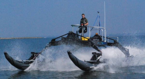
Experimental testing of the WAM-V prototype revealed an operability problem–-at high speeds the hull generates an intense water spray (see Figure 1). Beyond a critical speed the spray leads to reduced visibility and the operator (or the reconnaissance equipment) will get drenched. Both represent operational and also safety hazards, especially in cold climates where there is a heightened risk of marine ice formation.
|
| Figure 1: Spray generated by the WAM-V hull at 21 knots [25]. Courtesy of Prof. Mehdi Ahmadian, VirginiaTech, USA. |
Computer simulations are highly valuable to evaluate a wide range of ideas prior to construction and prevent the cost of purchasing components. The results of such simulations assist engineers in the decision making process towards better hull design that control and mitigate the spray formation.
The inflatable hull of the WAM-V is designed such that it displaces just a few feet below the waterline. It is reasonable to assume that the waterline never reaches the sub-structure connecting the hulls during the motion of the WAM-V. Therefore we just simulate the response of the free surface of the water due to the action of the WAM-V hull. A qualitative understanding of the physical conditions leading to spray generation can be obtained by simulating the action of just one hull.
|
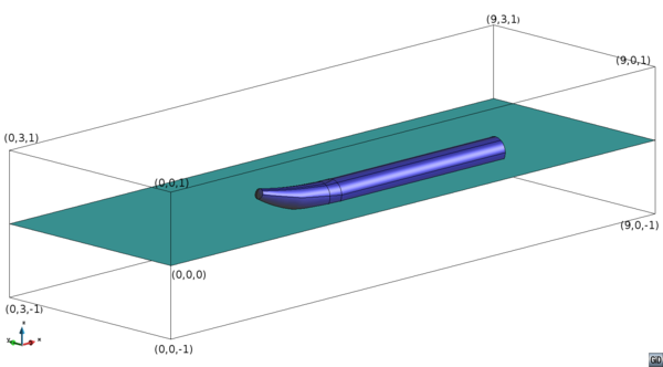
| Figure 2: The domain dimensions, location of the hull and the waterline. |
The domain is a 3D box with straight walls (see Figure 2) with dimensions: , and along the , and axes, respectively. The coordinates and represent two diagonally opposite corners of the domain. The face with coordinates , , and represents the plane of symmetry of the WAM-V. The geometry of the hull considered in the simulations corresponds to those of the WAM-V. The 3D space of the fluid domain is obtained by subtracting the volume occupied by the catamaran-type hull of the WAM-V from the volume of the containing 3D box. The draft of the hull, i.e. the displacement below the steady waterline is taken as .
The problem domain is discretized by a mesh of nodes and three-node tetrahedral elements. On an average twenty particles (material points that transport intrinsic properties of the fluid) per element were used in the simulations.
A pre-defined rigid body oscillatory motion is imposed as a transient boundary condition to model the pitch of the WAM-V hull. The pitch axis is parallel to the y-axis and passes through the point . The angle of rotation (in radians) about the pitch axis is taken as
|
|
(12) |
The background mesh is deformed every time step such that its internal boundary always conforms to that of the WAM-V hull. The mesh deformation scheme used is based on a Laplacian solver which is commonly used in the implementation of the Arbitrary Lagrangian–Eulerian formulations. This enables us to impose the no-slip velocity boundary conditions at the internal boundary in a straight-forward manner. The computer code used in this work was developed in the C++ programming environment KRATOS [26]. KRATOS is an open-source multi-physics software framework which provide a collection of tools useful to perform tasks that are useful to all FEM codes.
Water wave motion is generated by imposing the solution of a deep-water second-order Stokes wave in a narrow strip of water at the inlet and on the walls of the outlet.
|
where is the amplitude of the wave, is the angular wavenumber, is the acceleration due to gravity and is the angular frequency. Further is the velocity with which the WAM-V moves relative to water and , represent the spatial inlet velocity components of the water in an inertial reference frame that moves with the WAM-V. The narrow strip at the inlet where the wave velocity is imposed has a width of . This periodic velocity condition causes a disturbance which is propagated in the rest of the domain and whose motion is governed by the Navier–Stokes equations.
Three cases were studied which correspond to three different speeds of the WAM-V, viz. , and , respectively. The total physical time of simulation was chosen to be using time steps of each. All the three cases took nearly hours each to perform the computations using a workstation with an Intel® Core CPU and RAM. The computations were performed in parallel using four (available) cores and a single thread per core. Due to the very large mesh size ( million elements) and particle collection ( million particles), the memory requirements of these simulations are high; nearly of RAM.
|
|
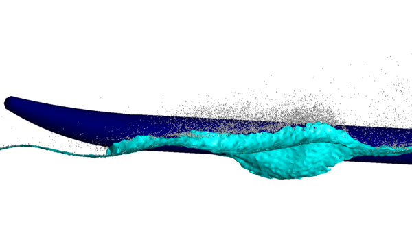
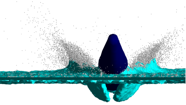
| Figure 3: Detail of the spray generated by the WAM-V hull at and time = . | |
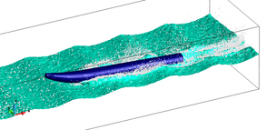
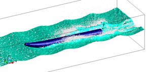
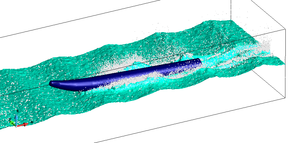
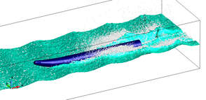
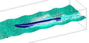
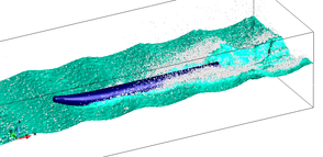
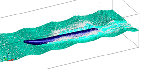
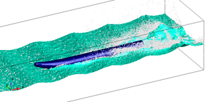
Figure 3 illustrates the details of the spray generated by the WAM-V hull moving at . Eight snapshots are shown in Figure 4 which correspond to a time interval (–) near the end of the simulation. In this sequence of snapshots we can see the initiation of the spray generation, its gradual development and a skewed separation from the axis of the WAM-V hull (cf. Figure 1). Near the end of this snapshot sequence we can see the process start over again. The spray generation (with respect to the location) at regular intervals is caused due to the presence of waves and the imposed pitch of the hull. The differences in the results obtained using and (not shown here) are in the height and intensity of the spray, which as expected increased gradually with the velocity.
|
|
|
|
|
|
|
|
| Figure 4: Simulation of the spray generated by the WAM-V hull moving at 25 knots using the SL–PFEM. | |
We see that the SL–PFEM is suitable for the seakeeping simulation of the WAM-V under spray generating conditions. Conventional CFD software tools are not suitable to reproduce spray generating conditions for this challenging problem. This is an example where particle-based incompressible flow simulation tools (e.g. SL–PFEM) stand out and deliver superior results.
In these simulations the water–air interface evolves in a very complicated manner. At any particular instant of time, all elements of the background mesh are labelled as water-element, air-element or interface-element. Each particle has an identity which is either air (label: +1) or water (label: -1). Within each element and at every time-step the particles transfer their identities to the element nodes. These contributions are weighted based on their location within the element and are assembled at the nodes. After the assembly, each node has an identity between -1 and +1. Following this line, a continuous piecewise linear approximation of the otherwise discrete identity data (on the particles) is obtained on the background mesh. The water–air interface is defined as the piecewise linear (planar) surface where the continuous piecewise linear approximate identity takes a value 0. The boundaries of the interface are determined at the resolution of the background mesh.
|
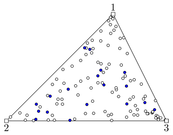
| Figure 5: Particles that compose the spray in an air-element. The water particles are shown as blue circles; the air particles are seen as white circles. |
In due course, situations may arise where there are regions within an air-element that are filled with water particles. There will also be interface-elements wherein we will find water particles on the air-side of the interface. These particles compose the spray generated in the simulations (see Figure 5). Should the pockets of water particles be large enough then it creates a situation where there are one or more water-elements surrounded by air-elements. These islands of water-elements are seen as water splash in the simulations which represent violent separation and/or merger of the interface. Naturally, such representation of water spray and its intensity depends on the number of particles chosen in the simulation. Nevertheless, the number of particles that compose the spray is not a representation of the mass of water in the spray. Recall that particles represent material points that carry with them only the intrinsic properties of the flow. So a smaller number of particles just mean that the spray representation is sampled at a coarser level of detail.
Other possible physical conditions which may generate spray are not modelled in the simulations. For instance, the viscous action of air motion may separate water particles from the interface or decompose existing water splash into water spray. Additionally, this phenomenon can happen at multiple scales wherein entities which can be classified as water spray at a coarse scale may be classified as water splash at a fine scale (which in turn can be decomposed into spray). This cascade will continue until surface tension forces comes to prominence and protect the integrity of the water droplets. Reproducing such physical conditions is out of the scope of the current implementation of the SL–PFEM.
Remark For a wide class of engineering applications the X-IVAS scheme usually admits very large time steps in the Lagrangain advection stage, e.g. – times the one given by the CFL condition. However in the simulations presented here we had to use small time steps (of the same order as the CFL limit) to control the accuracy of the solution. The reason for this limitation is discussed in the next section.
5 Trajectory approximation for Stokes waves
Consider a second-order Stokes wave in deep sea and position the 2D coordinate system at the height of the mean sea level. The solution of the free surface is
|
|
(16) |
Substituting in the equations (14) and (15 we obtain the solution of the velocity components.
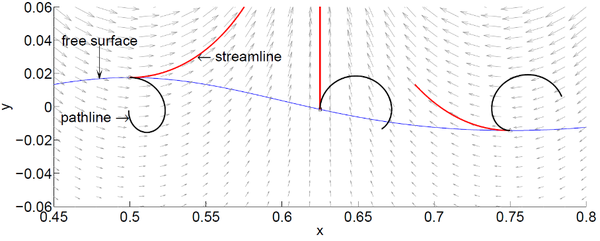
Consider the initial time step in the X-IVAS scheme and let the initial velocity and pressure be given by substituting in the exact solution. Figure 6 illustrates the streamlines of the initial velocity field originating at three distinct positions on the surface of the Stokes wave. Two of these initial positions are chosen as the crest and trough of the wave and the third point is chosen midway. In the X-IVAS scheme the computed trajectories are identical to the streamlines. The exact trajectories (pathlines) of particles initially located at these three points are also shown.
|
| Figure 6: Trajectory approximation in the X-IVAS scheme. The velocity field in the initial configuration is shown in the background as a vector plot. |
For the Stokes wave we see that the streamlines are not a good approximation to the pathlines. Recall that in the X-IVAS scheme we first compute tangent curves (streamlines) of the velocity vector field and choose them as the trajectories of the particles.
|
|
(17) |
Then we increment particle velocities by an amount equal to the line integral of the acceleration vector field along the streamlines.
|
|
(18) |
Therefore the updates in the particle position and its velocity within a time-step are decoupled in the X-IVAS scheme. In the Stokes wave propagation problem, transporting particles along the streamlines with large time steps will lead to significant errors in the configuration of the fluid domain. Now consider an alternative scheme for the Lagrangian advection: update the fluid particle position and velocity within a time-step using solutions to the following explicit second-order system of equations.
|
|
(19) |
Unlike in the X-IVAS scheme the solution of the above equation admits correction to the trajectories caused due to the updates in the particle velocities within a time-step.
|
|
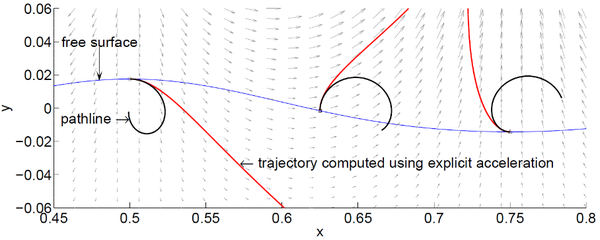
| Figure 7: Trajectory driven by the acceleration field (shown in the background as a vector plot) in the initial configuration. |
Figure 7 illustrates the trajectories driven by the initial acceleration field and originating at the considered three initial positions. Clearly the approximation in Figure 7 stands out as a higher fidelity model to the pathlines. Numerically stable formulas to compute the closed-form analytical solution of equation (19) will be done during the implementation of the Marie Skodowska-Curie action–-FastFlowSim1.
(1) http://cordis.europa.eu/project/rcn/200435_en.html
6 Conclusions
In the seakeeping simulation of the WAM-V, we have seen that the semi-Lagrangian Particle Finite Element method is a suitable CFD tool for the analysis of incompressible flows subjected to challenging physical conditions, e.g. violent interface motions, spray generating conditions etc. Due to the Lagrangian treatment of the advective processes and the Lagrangian data storage strategy in the SL–PFEM, the interfaces are accurately tracked. Further, the computational task associated to advective transport is mutually exclusive and hence scalable on parallel computers.
However, seakeeping simulations often involve water wave motion. Examining a second-order Stokes wave propagating on the surface of a deep sea, we have seen that the streamlines are not a good approximation to the pathlines. In such situations the use of large time steps in the X-IVAS scheme will result in significant errors in the fluid configuration. The particle trajectories driven by the acceleration in the initial configuration of the second-order Stokes wave are shown to be a better approximation to the pathlines. For seakeeping simulations with the SL–PFEM, this latter time-integration scheme seems to be a promising alternative to mitigate the small time-step limitation of the X-IVAS scheme.
7 Compliance with Ethical Standards
The authors declare that they have no conflict of interest. This study was partially supported by the WAM-V project funded under the Navy Grant N62909-12-1-7101 issued by Office of Naval Research Global, the SAFECON project (ref. 267521, FP7-IDEAS-ERC) and the FORECAST project (ref. 664910, H2020-ERC-2014-PoC) of the European Research Council (European Commission). The United States Government has a royalty-free license throughout the world in all copyrightable material contained herein.
Permission to use the image shown in Figure 1 has been granted by Prof. Mehdi Ahmadian, VirginiaTech, USA. This image has appeared earlier in Andrew William Peterson's Ph.D. thesis [25].
BIBLIOGRAPHY
[1] Idelsohn, Sergio Rodolfo and Oñate, Eugenio and Del Pin, Facundo. (2004) "The particle finite element method: a powerful tool to solve incompressible flows with free-surfaces and breaking waves", Volume 61. International Journal for Numerical Methods in Engineering 7 964–989
[2] Idelsohn, Sergio Rodolfo and Marti, Julio and Becker, Pablo and Oñate, Eugenio. (2014) "Analysis of multifluid flows with large time steps using the particle finite element method", Volume 75. International Journal for Numerical Methods in Fluids 9 621–644
[3] Idelsohn, Sergio Rodolfo and Nigro, Norberto and Limache, Alejandro and Oñate, Eugenio. (2012) "Large time-step explicit integration method for solving problems with dominant convection", Volume 217-220. Computer Methods in Applied Mechanics and Engineering 168–185
[4] WAM-V "The Wave Adaptive Modular Vessel". Marine Advanced Research, Inc.
[5] Courant, Richard and Isaacson, Eugene and Rees, Mina. (1952) "On the solution of nonlinear hyperbolic differential equations by finite differences", Volume 5. Communications on Pure and Applied Mathematics 3 243–255
[6] SAWYER, John Stanley. (1963) "A semi-Lagrangian method of solving the vorticity advection equation", Volume 15. Tellus 4 336–342
[7] Robert, André. (1981) "A stable numerical integration scheme for the primitive meteorological equations", Volume 19. Atmosphere-Ocean 1 35–46
[8] Min, Chohong and Gibou, Frédéric. (2006) "A second order accurate projection method for the incompressible Navier–Stokes equations on non-graded adaptive grids", Volume 219. Journal of Computational Physics 2 912–929
[9] Dupont, Todd F. and Liu, Yingjie. (2007) "Back and forth error compensation and correction methods for semi-lagrangian schemes with application to level set interface computations", Volume 76. Mathematics of Computation 258 647–669
[10] Dupont, Todd F. and Liu, Yingjie. (2003) "Back and forth error compensation and correction methods for removing errors induced by uneven gradients of the level set function", Volume 190. Journal of Computational Physics 1 311–324
[11] Selle, Andrew and Fedkiw, Ronald and Kim, ByungMoon and Liu, Yingjie and Rossignac, Jarek. (2008) "An Unconditionally Stable MacCormack Method", Volume 35. Journal of Scientific Computing 2-3 350–371
[12] MacCormack, Robert W. (2003) "The Effect of Viscosity in Hypervelocity Impact Cratering", Volume 40. Journal of Spacecraft and Rockets 5 757–763
[13] Harlow, Francis H. (1957) "Hydrodynamic Problems Involving Large Fluid Distortions", Volume 4. Journal of the ACM 2 137–142
[14] Evans, Martha W. and Harlow, Francis H. (1957) "The Particle-in-Cell Method for Hydrodynamic Calculations". Los Alamos National Laboratory. Library Without Walls Project 75
[15] Sulsky, Deborah and Zhou, Shi-Jian and Schreyer, Howard L. (1995) "Application of a particle-in-cell method to solid mechanics", Volume 87. Computer Physics Communications 1-2 236–252
[16] Zhang, Duan Z. and Zou, Qisu and VanderHeyden, W. Brian and Ma, Xia. (2008) "Material point method applied to multiphase flows", Volume 227. Journal of Computational Physics 6 3159–3173
[17] Gelet, Rachel Marie and Nguyen, Giang and Rognon, Pierre. (2015) "Modelling interaction of incompressible fluids and deformable particles with the Material Point Method". The 6th International Conference on Computational Methods (ICCM2015)
[18] Courant, Richard and Friedrichs, Kurt and Lewy, Hans. (1967) "On the Partial Difference Equations of Mathematical Physics", Volume 11. IBM Journal of Research and Development 2 215–234
[19] Celledoni, Elena and Kometa, Bawfeh Kingsley and Verdier, Olivier. (2015) "High Order Semi-Lagrangian Methods for the Incompressible Navier–Stokes Equations". Journal of Scientific Computing
[20] Nadukandi, Prashanth. (2015) "Numerically stable formulas for a particle-based explicit exponential integrator", Volume 55. Computational Mechanics 5 903–920
[21] Nielson, Gregory M. and Jung, Il-Hong. (1999) "Tools for computing tangent curves for linearly varying vector fields over tetrahedral domains", Volume 5. IEEE Transactions on Visualization and Computer Graphics 4 360–372
[22] Becker, Pablo and Idelsohn, Sergio Rodolfo and Oñate, Eugenio. (2014) "A unified monolithic approach for multi-fluid flows and fluid–structure interaction using the Particle Finite Element Method with fixed mesh". Computational Mechanics
[23] Idelsohn, Sergio Rodolfo and Nigro, Norberto Marcelo and Gimenez, Juan Marcelo and Rossi, Riccardo and Marti, Julio Marcelo. (2013) "A fast and accurate method to solve the incompressible Navier-Stokes equations", Volume 30. Engineering Computations 2 197–222
[24] Idelsohn, Sergio Rodolfo and Oñate, Eugenio and Nigro, Norberto and Becker, Pablo and Gimenez, Juan. (2015) "Lagrangian versus Eulerian integration errors", Volume 293. Computer Methods in Applied Mechanics and Engineering 191–206
[25] Peterson, Andrew William. (2014) "Simulation and Testing of Wave-Adaptive Modular Vessels". Virginia Polytechnic Institute and State University 476
[26] Dadvand, Pooyan and Rossi, Riccardo and Oñate, Eugenio. (2010) "An Object-oriented Environment for Developing Finite Element Codes for Multi-disciplinary Applications", Volume 17. Archives of Computational Methods in Engineering 3 253–297
Document information
Published on 01/01/2016
DOI: 10.1007/s40571-016-0127-2
Licence: CC BY-NC-SA license
Share this document
claim authorship
Are you one of the authors of this document?
