Abstract
The application of PFSA-based proton exchange membranes was investigated for the production of hydrogen and sulfuric acid using a SO2-depolarized electrolyzer system. Parameters investigated included hot pressing pressure for the membrane electrode assembly (MEA) manufacturing, cell temperature, membrane thickness, catalyst loading, membrane type, and SO2 anode feed concentration. The effect of cell temperature, membrane thickness, and acid concentrations was also investigated when using a second method, where clean sulfuric acid as cathode and SO2 saturated sulfuric acid as anode were used. Electrochemical impedance spectroscopy showed that the pressure exerted in the MEA manufacturing step had a significant influence with 125 kg cm−2 yielding the highest current density. High temperatures (>80°C) and thin membranes (≈120 μm) showed the best performance while thicker membranes produced higher acid concentration when using the first system. The SO2 concentration in the anode had a significant influence with the over potential increasing with decreasing SO2 concentration. When using the second method, it was found that the SO2 solubility in sulfuric acid is important as the mass transport of the SO2 limits the overall reaction rate. From the two systems tested, the first method, that is, dry SO2 anode and liquid water cathode showed the best operational effectiveness reaching a maximum of 0.32 A cm−2 at 80°C using N115 coated with 1 mgPt cm−2 while the second system under the same conditions achieved a current density of 0.18 A cm−2 when using N117.
Introduction
It is well known that the electrolysis of water is regarded as an alternative to the conventional methods for the production of hydrogen. With the development of proton exchange membranes (PEM), the interest in the electrochemical production of oxygen and hydrogen from water has significantly increased as PEM-based water electrolysis is an efficient and environmental friendly method that can be used for the production of hydrogen when zero-carbon power sources, such as renewable or nuclear, are used [1]. Also, the theoretical energy input for water electrolysis is 1.229 V with the practical operating voltage in the 1.7–2 V range. Attempts to increase the overall electrolysis efficiency have been made, for example, in the development of high temperature steam electrolysis [2]. More intricate systems have also been nominated as possible improvements on normal electrolysis including the thermochemical cycles. Almost 100 thermochemical cycles have been identified by the Department of Energy (DOE, USA), of which the sulfur-based cycles, specifically the sulfur iodine (SI) and the Hybrid Sulfur (HyS) cycles [3], seem most favorable. The HyS cycle, which is the focus of this study, requires a high temperature step (also present in the SI cycle),which has conventionally been assumed to be supplied by nuclear reactors, where sulfuric acid (H2SO4) is decomposed to SO2, H2O, and O2. Subsequently, the oxygen is removed as a product, whereas the SO2 and H2O are fed to an Platinum Group Metal catalyzed SO2 electrolyzer where the SO2 and water are converted to H2 and H2SO4 by means of a PEM (proton exchange membrane) electrode assembly (MEA) [4]. The overall reaction for the electrolysis step is shown in equation (1).
|
|
(1) |
The produced H2SO4 is recycled to the decomposer to complete the cycle [5]. By making certain assumptions for the decomposer and separation step, Gorensek and Summers [3] showed that when operating the electrolyzer at 0.6 V and 0.5 A cm−2, the entire HyS cycle can achieve a thermal to electrical efficiency of 47% [3]. The advantage of the SO2 depolarized electrolysis is that the theoretical potential needed to drive the electrolysis step is only 0.158 V [4] with practical potentials of 0.5–0.9 V, which is considerably lower than that of water electrolysis. However, for the electrolyzer to be economically feasible, the hydrogen produced must be of high purity as its purity is essential when used in the fuel cell market where it has been clearly shown that impurities, such as SO2, reduce the operation efficiency of a fuel cell dramatically [6]. On the other hand, a high concentration of sulfuric acid (in the range of 65 wt% [7]) is needed to ensure that the subsequent HyS decomposition step is efficient enough to make the entire HyS cycle competitive compared to other hydrogen production methods currently being explored [8].
When the Westinghouse Corporation initially developed the SO2 electrolyzer in the 70s, it was run using a diaphragm as separator, where clean sulfuric acid was fed to the cathode and sulfuric acid saturated with SO2 gas was fed to the anode [5]. Although initial results were poor due to the high ohmic resistance of the separator and the limited mass transport of the SO2 gas in the acid, it did show the potential of SO2 depolarized electrolysis.
Sivasubramanian et al. [4] showed that the performance of the SO2 electrolyzer can be increased by exchanging the diaphragm with polysulfonic acid (PFSA)-based PEM, such as Nafion®, and supplying the cathode with liquid water and the anode with dry SO2 gas. More recently, Staser and Weidner [9] showed that the cell voltage can be decreased further by increasing the cathode water pressure, whereby the authors almost reached the desired electrolyzer operating conditions initially proposed by Gorensek and Summers [3], reaching 0.760 V at 0.5 A cm−2. The acid concentration produced was, however, not sufficient for recirculation to the decomposer. Other aspects that need further attention include the SO2 crossover from the anode to the cathode leading not only to the removal of unreacted SO2 but also to an increased cell voltage due to catalyst poisoning on the cathode while simultaneously producing unwanted and potentially toxic gasses such as H2S in the H2 product stream. Although the high cathode pressure used by Staser et al. [10] significantly reduces the SO2 crossover, further work is required to increase the produced acid concentration.
In this study, an extensive preliminary evaluation of commercial PFSA-based PEM for use in SO2 electrolysis is reported. The various parameters include hot pressing pressure used in the MEA manufacturing step, operating cell temperature, catalyst loading, membrane thickness, membrane type, and SO2 concentration in the anode. Furthermore, the effect of using clean sulfuric acid as the cathode feed and SO2 saturated sulfuric acid as the anode feed (as was used initially in the HyS cycle) was evaluated by varying the cell temperature, membrane thickness, and acid concentration used. The main objective of the study was to systematically determine the influence of various operating parameters including cell temperature, membrane thickness, and catalyst loading on the performance of the SO2 electrolyzer.
Experimental Methods
General operating procedure
All membrane samples, including both the Nafion® (Ion Power, New Castle, DE) and the modified PFSA membranes (FZP-50; Fumatech, St. Ingbert, Germany) were pretreated in 1 mol/L H2SO4 at 80°C for 90 min [4] unless stated otherwise. Membrane electrode assemblies were manufactured by hot pressing (model# 3912; Carver, Wabash, IN) the membranes between two commercial gas diffusion electrodes (FuelCellEtc, College Station, TX), consisting of carbon cloth and a microporous layer onto which the catalyst loading had been deposited. A pressure of 125 kg cm−2, unless stated otherwise, at a temperature of 120°C for 5 min was used. The hot-pressed MEAs were stored in a plastic bag in DI water until use. Before SO2 electrolysis, all MEAs were hydrated at the intended operating temperature for at least 2 h within the electrolyzer. Electrolysis was achieved by supplying dry SO2 gas (150 mL min−1) to the anode using a thermal mass flow controller, while DI water was circulated through the cathode compartment as previously described [11]. The acid produced was collected in a glass separation vessel at the anode side. Figure 1 shows the experimental system, where a 25 cm2 electrolyzer (Fuel Cell Technologies, Albuquerque, NM) was used unless stated otherwise.
|
|
|
Figure 1. Schematic of the experimental SO2 electrolysis setup with a liquid cathode and a dry SO2 anode feed with (1) SO2 flow meter, (2) SO2 electrolyzer, (3) cathode, (4) anode, and (5) glass acid separator. |
All membranes were preconditioned by running the electrolyzer at 0.1 A cm−2 for 20 min before the polarization curve was started. The polarization curves were obtained by increasing the current density incrementally every 90 sec while recording the voltage. The system used was controlled by a Labview® (National Instruments, Midrand, South Africa) program.
Electrochemical impedance spectroscopy (EIS) analysis was applied using a Gamry REF300 (Gamry Instruments, Warminster, PA) potentiostat equipped with a frequency response analyzer. The impedance of the electrolyzer was measured galvanostatically with a perturbation signal of 10% (2% at current densities higher than 0.25 A cm−2 to avoid voltages above 1.1 V) with a frequency range of 10 kHz to 10 mHz. The anode was used as the working electrode, while the cathode served as both the counter and reference electrode. An electrical circuit was fitted (refer to references [12, 13] for electrical circuit) to the data to, using the Gamry software, determine the membrane resistance, charge resistance, and mass transport effect as described previously [12, 13].
Variables tested
From literature it has been shown that the performance of the SO2 electrolyzer is influenced by cell temperature, pressure, membrane thickness, catalyst loading, SO2 concentration supplied to the anode, sulfuric acid concentration produced at the anode, and water transport within the MEA.
The effects of various parameters were investigated in this study to determine their influence on SO2 electrolysis. These parameters include hot pressing pressure, temperature, catalyst loading, membrane thickness, membrane type, and the SO2 concentration supplied to the anode. Finally, a second system was used to evaluate the effect of using SO2 saturated sulfuric acid as the anode and clean sulfuric acid as the cathode where the effect of cell temperature, membrane thickness, and acid concentration on cell performance were determined.
The effect of the applied pressure during MEA hot pressing was evaluated in a pressure range of 50–140 kg cm−2. Both the pressing temperature and time were kept constant at 120°C and 5 min, respectively, while both polarization curves and EIS were used for characterization.
To determine the influence of temperature on electrolysis [14], the system was operated at temperatures ranging from 50°C to 90°C (each with a new MEA) using N117 and a catalyst loading of 1 mgPt cm−2. Since reaction kinetics are generally increased using a higher catalyst loading [14], three catalyst loadings were tested including 0.3, 0.5, and 1 mgPt cm−2. It should be noted that the 1 mgPt cm−2 catalyst loading contained platinum black (with no supporting material), while both the 0.5 and 0.3 mgPt/C cm−2 contained platinum on a carbon support. The notation of Pt/C will be used to indicate the platinum supported on carbon catalyst.
As it has been previously shown that the water transport through the membrane influences the SO2 electrolysis even when a water pressure gradient was used [9], the effect of membrane thickness was investigated by additionally measuring the sulfuric acid concentration and the specific resistance. The acid concentration was determined by titration with 0.1 mol/L NaOH and phenolphthalein as indicator, while the area specific resistance (Ω cm2) was measured using a high-frequency milliohm meter (HP, 4328A, Test Equipment, Lake Mary, FL).
It has been shown for fuel cell applications that the type and configuration of PFSA-based materials, such as different side chains on the Polytetrafluoroethylene-type backbone [15], different equivalent weights being used [15], and alterations to the membrane configuration to promote proton conductivity [16] influence performance. It was shown that by including zirconium particles within the membrane matrix, the membranes water content increases at higher temperatures [16]. To determine this influence on SO2 electrolysis, such a zirconium containing membrane (FZP-50, Fumatech) was evaluated using 1 mgPt cm−2 at 80°C and compared to a commercial Nafion® based N115.
While previous literature used pure SO2 gas [4] as the anode, this is not always possible when the electrolyzer is connected to an industrial process such as a coal firing plant [17], where the concentration of SO2 is depleted after the scrubbing methods to reduce SO2 emissions. Hence to determine the influence of the SO2 concentration, the electrolyzer performance was determined using a SO2 feed concentration ranging 10–100% (v/v) where N2 gas was used to dilute the SO2.
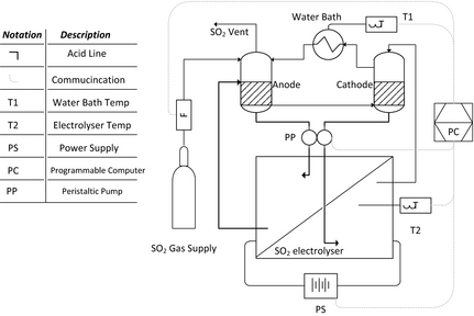
To determine the influence of dry SO2 gas versus a SO2 dissolved in diluted H2SO4 feed, clean sulfuric acid was supplied to the cathode and SO2 saturated sulfuric acid to the anode as schematically illustrated in Figure 2. Two double walled glass containers each with a volume of 250 mL (±5 mL) were used as the anode and cathode feed compartment, respectively. Batch solutions (2000 mL) of 30 and 65 wt% sulfuric acid were prepared by diluting 98 wt% H2SO4 in DI water (18 MΩ cm). Each glass container was filled with 50 mL of acid. The temperature of the acid solutions was controlled by circulating preheated water through the outer compartments using a FED-12ED Julabo water bath. Prior to the application of a current, SO2 gas was bubbled through the anode compartment for at least 2 h at 50 mL min−1 to ensure saturation, while the cathode solution was purged with N2 gas. No pressure was used to increase the SO2 content in the anode compartment due the glass construction of the vessels.
|
|
|
Figure 2. Schematic representation of the SO2 electrolyzer system used with an acid cathode and a SO2 saturated anode feed. |
Both anode and cathode solutions were circulated through the electrolyzer cell back to the glass containers using a peristaltic pump (WMB, Du520; Johannesburg, South Africa). The same DC power supply was used as for the liquid cathode/dry SO2 anode system (Fig. 1). Polarization curves were obtained by increasing the applied current incrementally every 90 sec. For this investigation, scanning electron microscope (FEI Quanta 250 FEG with ESEM capabilities) images were made of the membrane electrode assemblies for characterization purposes after 3 h of operation at 0.1 A cm−2 and 50°C and 80°C, respectively. Additional cross-sectional images are shown for N115 and N117.
Results and Discussion
The selection of operational parameters is a critical component when SO2 electrolysis is used for the production of both hydrogen and H2SO4. In order to compare data more conveniently, all the parameters were tested using N117 unless stated otherwise.
Influence of hot pressing pressure
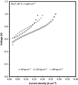
It has been previously reported that the hot pressing pressure does influence the operational efficiency of the PFSA-based membranes, specifically in fuel cells [18]. For this reason, the pressure exerted in the hot pressing step was varied from 50 to 140 kg cm−2 where both polarization curves and EIS were used to evaluate the effect of the pressure used on the performance. Figure 3 shows the polarization curves for N117 at 80°C with a catalyst loading of 1 mgPt cm−2. From Figure 3 it is interesting to notice that the 50 and 140 kg cm−2 are comparable at low current densities (<0.03 A cm−2), while the 50 kg cm−2 pressure has better performance up to 0.14 A cm−2. With increased current density (>0.15 A cm−2) the 140 kg cm−2 pressure shows both better performance and reached higher current density than the 50 kg cm−2. The 125 kg cm−2 pressure shows the best performance irrespective of the current density used. It should also be noticed that the 125 kg cm−2 reached almost 0.3 A cm−2 (0.1 A cm−2 more than the 140 kg cm−2). It has been shown that the pressure applied in the MEA manufacturing step for fuel cell application also influences performance [18]. A change in the gas diffusion electrode (similar to the one used in this study) gas permeability was observed for gasses. Thus, the permeability of the reactant SO2 to the anode as well as the produced H2SO4 permeability from the anode to the flow field should also be influenced significantly.
|
|
|
Figure 3. Polarization curves as a function of hot pressing pressure for N117, 1 mgPt cm−2 at 80°C. |
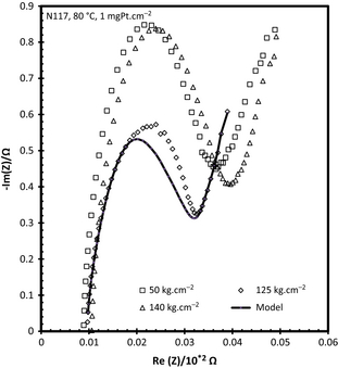
To determine why the pressure influences the overall performance of the electrolyzer, EIS is shown at 0.15 A cm−2. Although EIS data were produced at other (higher) current densities for 50 and 125 kg cm−2 (data not shown), the highest current density reached for 140 kg cm−2 was used for comparison. The current density was selected as the 50 kg cm−2 could only reach 0.17 A cm−2, that is, the perturbation current signal of 0.1 A would cause the voltage to increase above the 1 V corrosion limit set by the use of graphite flow field plates.
Figure 4 illustrates the EIS data attained for the various hot pressing pressures. It is apparent that the membrane resistance (interception with the x-axis) was not significantly influenced by the hot pressing pressure as has been previously reported in literature [19]. By visual inspection, Figure 4 confirms the improved polarization curve attained for the 125 kg cm−2 compared to the 50 kg cm−2 hot-pressed MEA due to the improved charge transfer characteristics as shown by the width of the semicircle.
|
|
|
Figure 4. Nyquist plots for SO2 electrolysis as a function of MEA hot pressing pressure. The EIS shown were performed at 0.15 A cm−2. MEA, membrane electrode assembly; EIS, electrochemical impedance spectroscopy. |
Mass transport effects can be identified by the straight line in the low frequency range in Figure 4 (far right of the x-axis) and is present at all pressures used [18]. Using the electrical circuit as previously described [18], a model fitment could be made to separate the membrane resistance, charge resistance, and mass transport limitations. The data obtained from the model (data not shown) support the assumption made regarding the membrane resistance was confirmed with the membrane resistance increasing slightly from 8.30 to 10.20 mΩ when the pressure is increased from 50 to 140 kg cm−2, respectively. While the charge resistance was comparable between 125 and 140 kg cm−2 (20.98 vs. 28.50 mΩ) while the 50 kg cm−2 had the highest resistance of 56.90 mΩ. The mass transport limitations increased as the applied hot pressing pressure increased. It is clear that the most influential factor for performance, at 0.15 A cm−2, appears to be the charge resistance as this is the only parameter in which the 125 kg cm−2 is better than the 50 and 140 kg cm−2.
Influence of temperature
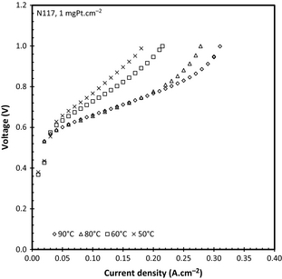
The effect of temperature on the cell performance for the 25 cm−2 active area acid electrolyzer is shown in Figure 5 for N117 (±170 μm) using a 1 mgPt cm−2 catalyst loading. Experiments were repeated at 50°C and 80°C showing an error of 5% on the operating voltage. Sivasubramanian et al. [4] showed that at low current densities, and no cathode water pressure, the water diffusion from the cathode to the anode provides sufficient water for the reaction. This is, however, not true at current densities above 0.4 A cm−2, where the water drawn to the cathode due to electro-osmotic drag offsets the natural diffusion of water through the membrane. This was confirmed in this study showing the clear limit on the current density attainable due to the water mass transport limitations. It is well known that the uptake of water by PFSA-based membranes is temperature dependant, that is, increasing the proton conductivity of the membrane, with an electro-osmotic drag coefficient of 2 at 20°C compared to the 3.3 at 90°C at a constant current [20]. The significant increased performance for the SO2 electrolyzer with increased temperature can be attributed to the higher proton conductivity (due to higher water uptake). However, Staser et al. [21] have shown that the solubility coefficient (cm2 sec−1) during the crossover of SO2 from the anode to the cathode increases with increasing temperature which can reduce the hydrogen evolution efficiency dramatically.
|
|
|
Figure 5. Temperature effect on SO2 electrolysis using N117 and 1 mgPt cm−2. |
Table 1 shows both the acid concentration and the high frequency values (area specific resistivity, Ω cm2) as a function of temperature and current density for N117. It can be seen that the cell temperature did not have a significant influence on the area specific resistance at any current density. However, the resistance did increase as a function of the current density. This has also been illustrated by Staser et al. [22] who obtained an increase in the resistance as a function of the acid concentration produced, that is, current density.
| Current density (A cm−2) | 50°C | 60°C | 80°C | 90°C | ||||
|---|---|---|---|---|---|---|---|---|
| [H2SO4] (mol L−1) | RAC (Ω cm2) | [H2SO4] (mol L−1) | RAC (Ω cm2) | [H2SO4] (mol L−1) | RAC (Ω cm2) | [H2SO4] (mol L−1) | RAC (Ω cm2) | |
| 0.05 | 4.75 | 0.1 | 4.38 | 0.125 | 4.5 | 0.125 | 4.44 | 0.1 |
| 0.1 | 6.88 | 0.1 | 6.63 | 0.125 | 4.53 | 0.125 | 5.81 | 0.1 |
| 0.15 | 6.72 | 0.11 | 8.28 | 0.15 | 7.1 | 0.138 | 6.56 | 0.1 |
| 0.18 | 7.5 | 0.125 | – | – | – | – | – | – |
| 0.2 | – | – | 9.81 | 0.163 | 6.88 | 0.138 | 6.94 | 0.11 |
| 0.25 | – | – | – | – | 7.44 | 0.138 | – | – |
| 0.28 | – | – | – | – | – | – | 12.69 | 0.125 |
When considering the acid concentration, it is clear from Table 1 that at 50°C the acid produced is slightly more concentrated than at 60°C for current densities below 0.15 A cm−2. However, when the current density was increased above 0.15 A cm−2 the acid concentration increased from 50°C to 60°C. While this tendency did not hold when increasing to 80°C, it is noticeable that an acid concentration of 12.69 ± 0.2 mol L−1 (corresponding to 55 wt%) was reached at 90°C at 0.28 A cm−2. While this product acid is the most concentrated H2SO4 attained under these conditions, the concentration is below the optimum concentration for the HyS cycle, which should be in the region of 65 wt% [7]. It is clear from the results presented that to increase the concentration of the acid the cell would have to run at higher current densities while maintaining a reasonable operating voltage. Staser et al. [22] showed that the area specific resistance increases significantly with increased acid concentration produced although a water pressure on the cathode was used.
Influence of catalyst loading
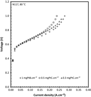
Since the catalyst loading is important when considering large scale operation of any process due to cost, the effect of the catalyst loading was also included in this study using N117 for comparative purposes. Figure 6 shows the data obtained for the different catalyst loadings tested. It is clear that at low current densities the cell performance is almost identical. This is probably due to the low reaction rate of SO2 at the anode allowing the water enough time to diffuse through the MEA. A slight difference (37 mV when comparing 0.5 and 0.3 loadings) can, however, be observed when the current densities are above 0.18 A cm−2, where the 1 mgPt cm−2 achieved a higher current density when compared to the 0.5 or 0.3 mgPt/C cm−2. This effect has not been seen when a differential pressure is applied where it has been shown that the catalyst loading of 1.5 mgPt cm−2 versus 0.5 mgPt/C cm−2 had little to no effect on cell performance [9] using catalyst coated membranes. It must be noted that the particle size and catalyst wt% in the ink used to manufacture the gas diffusion layers (GDEs) also influence the overall catalyst utilization [23] making a direct comparison more difficult as the supplier of the GDEs has confirmed that the PtB catalyst particle size was 9 μm while the Pt/C (60 wt%) catalyst was 4.0–5.5 nm. However, the aim of this specific study was to compare the two different commercial catalysts which unfortunately were not available with the same catalyst particle size.
|
|
|
Figure 6. Effect of catalyst loading on cell voltage at 80°C. |
In a recent study, Lee et al. [24] investigated the effect of catalyst loading on SO2 oxidation using a three electrode system. They were able to show that the Pt utilization is influenced significantly by the electrochemical surface area showing a decrease in utilization with increasing Pt loading [24]. In spite of this inverse proportionality, they were able to show that the exchange current density increases from 9.0 × 10⁻⁹ to 2.7 × 10⁻⁵ A cm−2 when the Pt loading was increased from 0.4 to 4.02 mgPt cm−2. The area specific resistance was also measured for each catalyst loading and no considerable difference could be established with the resistivity being in 0.14–0.15 Ω cm2 region.
Influence of membrane thickness
Although literature does provide ample information on the effect of membrane thickness on the cell performance when operating under a differential pressure, it does not supply data on its affect at ambient anode and cathode pressures [9]. This is illustrated in Figure 7 showing the effect of membrane thickness for three different Nafion membranes on SO2 electrolysis. All MEAs were produced using 0.5 mgPt/C cm−2 GDEs.
|
|
|
Figure 7. Effect of membrane thickness on SO2 electrolysis performance at 80°C. |
When considering the membrane thicknesses of these membranes (N115 = 122 μm; N117 = 170 μm; and N1110 = 245 μm) it is evident that the membrane thickness has a significant influence on the cell performance in terms of current density with N115 reaching 0.32 A cm−2 compared to 0.17 A cm−2 achieved by N1110. It is well known that the water permeation of Nafion® membranes is dependent on membrane thickness with thicker membranes having a lower diffusion coefficient [25]. Thus, at a constant current density and temperature the total water flux to the anode will increase for thinner membranes. This effect will then, in turn, decrease the acid concentration of thinner membranes while thicker membranes will produce more concentrated sulfuric acid. This was confirmed when considering Table 2, where the acid and the area specific resistance as a function of membrane thickness at a constant temperature of 80°C are shown.
| Current density (A cm−2) | N115 | N117 | N1110 | |||
|---|---|---|---|---|---|---|
| [H2SO4] (mol L−1) | RAC (Ω cm2) | [H2SO4] (mol L−1) | RAC (Ω cm2) | [H2SO4] (mol L−1) | RAC (Ω cm2) | |
| 0.05 | 2.5 | 0.1 | 5.063 | 0.14 | 7 | 0.15 |
| 0.1 | 4.53 | 0.1 | 7.25 | 0.14 | 7.38 | 0.18 |
| 0.15 | 6.88 | – | – | 0.13 | 8.94 | 0.19 |
| 0.2 | 7.4 | 0.11 | 7.75 | 0.15 | – | – |
| 0.25 | 7.44 | 0.12 | 8.69 | 0.15 | – | – |
| 0.32 | 8.84 | 0.14 | – | – | – | – |
Although cell temperature does influence the operating voltage, it has been shown that the acid concentration influences the reaction kinetics of SO2 reduction as well as the average membrane conductivity even when using a differential pressure [22]. As in Table 1, the area specific resistance seemed to increase with increasing current. In addition, the resistance also showed an increase with increasing membrane thickness, where the resistance of N1110 (at 0.1 A cm−2) was nearly twice that of N115. The increasing resistance with increasing current density can be attributed to the produced acid concentration. As N1110 had lower water diffusing to the anode, the acid would be more concentrated compared to N115 and N117. This increase of acid concentration with membrane thickness has also been reported by Staser et al. [20, 22] when using a pressure differential. Although the acid concentrations are lower due to the permeating water (pressure driven effect) the effect of membrane thickness on acid concentration is still present. It is also interesting to note that the acid concentration increased more rapidly for N115 (increased by 6.34 mol L−1 from 0.05 to 0.32 A cm−2) than for N117 (increased by 3.63 mol L−1 over the same current density range).
Comparison of N115 and FZP-50
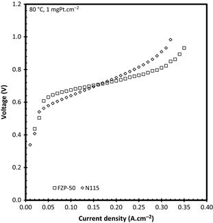
While Nafion® is the commercial standard membrane used for water electrolysis and therefore often referred to for SO2 electrolysis, there are other PFSA-based PEM of interest. One example is a novel FZP-50 PFSA-based PEM from Fumatech, which was evaluated using ambient pressure at 80°C with a 0.5 mgPt/C cm−2 catalyst loading. Figure 8 shows the comparative performance of N115 and FZP-50 during SO2 electrolysis. It is clear that the FZP-50 yielded lower voltages at current densities above 0.2 A cm−2 than N115. Although the membrane thickness of the FZP-50 is almost 40 μm thinner than the N115 it does show that alternative PFSA membranes are suitable for SO2 electrolysis.
|
|
|
Figure 8. Comparison between N115 and FZP-50 PFSA membranes at 80°C and 1 mgPt cm−2. |
The FZP-50 PFSA membrane contains zirconium oxide within the polymeric membrane to facilitate water sorption which was initially manufactured for operation of PEM Fuel Cells at temperatures close or higher than 100°C where PFSA membranes have the drawback of losing conductivity (and in turn its water content). It is clear that this improved ability to retain water within the PFSA membrane is advantageous in the SO2 electrolyzer especially at higher current densities as can be seen from Figure 8. According to the measurements, the ohmic resistance of FZP-50 remained near constant increasing only 0.01 Ω cm2 over the entire operating current density, while the N115 increased from 0.1 to 0.14 Ω cm2 showing that the FZP-50 membrane is more stable (better proton conductivity at high acid concentration) in an acid environment than the N115. The acid concentration produced was similar for the two membranes with N115 producing a slightly higher acid concentration (8.84 vs. 7.2 mol L−1 at 0.32 A cm−2).
Influence of SO2 feed concentration
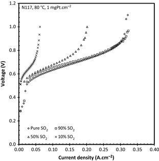
As previously mentioned, the SO2 anode feed concentration is important when the SO2 supply for the electrolyzer is to be obtained from other sources such as industrial processes that do not necessarily supply a 100% pure SO2 gas. To determine this influence, the performance of the SO2 electrolyzer fed with a reduced concentration of SO2 was investigated. In Figure 9 the results obtained when feeding the anode concentrations of 100%, 90%, 50%, and 10% (v/v) SO2 gas using 1 mgPt and N115 at 80°C.
|
|
|
Figure 9. Effect of reduced SO2 concentration on SO2 electrolysis. |
The significant increase in the potential with decreasing SO2 concentration at constant current density was to be expected in view of the starvation of the anode reactant. This effect has also been shown by Jeong et al. [26] who did, however, show that better (reaching a 0.2 A cm−2 for 20% SO2) performances could be attained at higher temperatures, although it was not clear if a pressure difference was used. The overall voltage increase can be linked both to the decreased amount of SO2 available and to the increased diffusion paths of the SO2 through the N2. The voltage penalty caused by reducing the SO2 concentration from 100% to 50% is 225 mV at 0.2 A cm−2. A possible mitigation step apart from the increased temperatures suggested by Jeong et al. [26], could be to increase the anode pressure which would reduce the operating potential at lower SO2 concentrations. This would increase the SO2 concentration while improving the operating voltage and attainable current density.
Influence of feed stream configuration
Operating the SO2 electrolyzer using alternative configurations is possible, for example, by using clean sulfuric acid as the cathode feed and SO2 saturated sulfuric acid as the anode reactant feed [27]. This configuration was investigated varying the operating temperature, the membrane thickness, and the acid concentration. For this configuration either N115 or N117 were used.
Influence of temperature
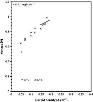
Figure 10 illustrates the effect of temperature on the performance of SO2 electrolysis using a 30 wt% sulfuric acid solution. N117 was used with a catalyst loading of 1 mgPt cm−2 and an electrolyzer with a 25 cm2 active area. It was expected that the overall performance would increase with increasing temperature as had been observed in the SO2 dry anode fed results presented in Figure 5. This was however not the case when the SO2 was dissolved in H2SO4, which can probably be ascribed to the solubility of SO2 in H2SO4. It has been shown [28, 29] that the solubility of SO2 gas in 30 wt% decreases with increasing temperature at a constant pressure thereby reducing the amount of SO2 gas available for the reaction resulting in an increased operating voltage.
|
|
|
Figure 10. Effect of cell temperature on cell performance using acid/acid feed and N117. |
The presence of the relatively high over potential (compared to using SO2 anode feed – see Fig. 5) is also due to the fact that the dissolved SO2 gas has a significantly lower diffusivity in the liquid H2SO4 than it would have in a gas. The lower SO2 concentration combined with the mass transport limitation resulted in a maximum operational current density of 0.2 A cm−2. It should be reported that the system had fairly poor voltage stability at 50°C with an increase of 100 mV per hour which could have been caused by the poor reaction kinetics. It has been shown that various parameters such as the Nafion® content in the catalyst layer and MEA hot pressing temperature can be optimized to increase the overall cell performance [27]. However, at 80°C there was no significant increase in voltage.
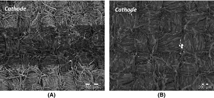
Figure 11 shows surface SEM images taken after electrolysis from the cathode for both the 50°C and 80°C MEAs. According to Figure 11A, it is clear that some sulfur deposition (determined with energy-dispersive x-ray (EDX) analysis and visible as the light gray area between the carbon fibers) has occurred on the GDE used at 50°C. This deposition of sulfur is due to SO2 diffusion from the anode to the cathode where possible parasitic reactions can occur [9, 30] producing elemental sulfur or H2S gas, although no odor was apparent during operation. The cathode acid turned light milky indicating that H2S and SO2 dissolved in the liquid. The darker area in Figure 11A is the land area of the flow field showing that the sulfur produced is only present within the flow field area. Although this article has shown that SO2 crossover does occur, we have previously illustrated that the operating voltage remained constant over an extended period of time for a similar system (100–150 h.) [11, 31] confirming that sulfur deposition did not results in significant decrease in performance.
|
|
|
Figure 11. SEM images of the cathode GDE surface after SO2 electrolysis at 50°C (A) and 80°C (B). |
Figure 11B shows the cathode surface after electrolysis at 80°C. Although there is less (determined by visual inspection) sulfur deposited on the surface, its presence confirms that even with a reduced amount of SO2 dissolved (due to increased solution temperature) some SO2 did diffuse through the membrane.
Influence of membrane thickness
The effect of membrane thickness (N117 vs. N115) was also investigated for this system using 1 mgPt cm−2 GDEs at 80°C. The results are shown in Figure 12. In view of the data obtained from the liquid cathode and dry SO2 anode experiments (Fig. 7), it was expected that the thinner membrane would perform better. However, for this configuration the thicker N117 membrane showed a slightly better performance. This effect can be explained in terms of the SO2 transport across the membrane. As the SO2 flux across the membrane is dependent on the membrane thickness [9], it can be expected that N115 allowed more SO2 to the cathode than N117. The presence of SO2 at the cathode has been shown to reduce cell performance by increasing the cell potentials [32].
|
|
|
Figure 12. Effect on membrane thickness on cell performance when using acid/SO2 acid reactants. |
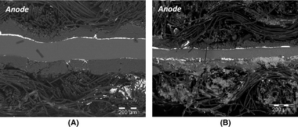
In order to show this effect more clearly SEM images were taken of the cross section of each MEA after electrolysis (Fig. 13). From the SEM images one can clearly see the membrane thickness difference between the N117 and N115. When considering the sulfur deposition observable from the cross section of the N117 MEA (Fig. 13A), it is clear that only small amounts of sulfur had been deposited on the cathode side of the MEA confirming the observations made earlier for N117 (Fig. 11B). From Figure 13B, it is clear that significantly more sulfur had been deposited on the cathode explaining its worse performance.
|
|
|
Figure 13. Cross-sectional view of N117 (A) and N115 (B) membrane electrode assembly after SO2 electrolysis. |
Influence of H2SO4 concentration
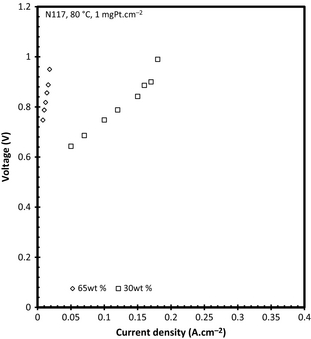
To determine the effect of acid concentration the performance was determined using a 30 wt% and a 65 wt% H2SO4 feed solution. It is clear from the V–i curve (Fig. 14) that a higher over potential was present when using the more concentrated 65 wt%. This can be attributed to the low solubility characteristics of SO2 gas in more concentrated acid solutions. Gorensek et al. [28] showed that the SO2 solubility decreased from 0.748 to 0.665 g SO2 per 100 g H2SO4 when the acid concentration was increased from 30 to 65 wt% at constant pressure and temperature. In addition, the diffusion of the SO2 from the solution to the anode catalyst will decrease with increasing sulfuric acid concentration as the viscosity of the acid increases from 1 (39.92 wt% H2SO4) to 2.8 centipoise (65.13 wt% H2SO4) at 80°C [30]. The open circuit voltage determined for both acid concentrations was 0.183 V (30 wt%) and 0.265 V (65 wt%), respectively. These values can be compared to the values obtained theoretically (from the Nernst equation using an OLI MSE model-generated species activities) by Gorensek et al. [28] who reported a theoretical reversible potential of 0.206 V (30 wt%) and 0.347 V (60 wt%) at 80°C for an SO2 electrolyzer operated with a liquid cathode and a dry SO2 anode under 6 bar differential pressure. The higher reversible potential as a function of acid concentration might be due to the adsorption of sulfur species to the anode before any current is available. The data shown here, for the 30 wt% case, also correspond well with that of literature operating at 0.97 V at 0.18 A cm−2 versus 0.95 V [27].
|
|
|
Figure 14. Effect of H2SO4 concentration used for the acid/SO2 acid system at 80°C when using N117. |
Conclusion
Various parameters influencing SO2 electrolysis were investigated including a liquid cathode and dry SO2 anode fed system where the influence of hot pressing pressure, cell temperature, catalyst loading, membrane thickness, membrane type, and SO2 concentration were investigated. Subsequently the reactant configuration was changed to a clean sulfuric acid cathode feed and a SO2 saturated H2SO4 feed setup, where the influence of cell temperature, membrane thickness, and acid concentration used was determined. It was found that performance was influenced by the hot pressing pressure during MEA manufacturing, while higher cell temperature, thinner membranes, and operating at low current densities improved performance. The highest acid concentration (which is beneficial to the HyS cycle) of 12.69 mol L−1 was attained (at 0.993 V) using a N117 at 90°C and 0.28 A cm−2. The effect of catalyst loading showed little influence at low current densities (<0.2 A cm−2) although the 1 mgPt cm−2 loading showed slightly better performance at higher current densities. The overall cell voltage was a strong function of SO2 concentration supplied to the anode showing an increase in voltage as the SO2 concentration was decreased. Considering both acid concentration and operating voltage, the optimal operating conditions for the electrolyzer would be at 80°C, using N115 and 1 mgPt cm−2. It was shown that the SO2 solubility in sulfuric acid is crucial when the cathode is supplied with clean sulfuric acid and the anode with SO2 saturated sulfuric acid. Increasing the cell temperature from 50°C to 80°C showed a decrease in performance (due to a decrease in SO2 solubility in sulfuric acid as temperature is increased). Decreasing membrane thickness also resulted in high over potential which is probably due to increased SO2 crossover from the anode to the cathode.
Acknowledgments
The authors thank the DST (Department of Science and Technology, South Africa) for their financial support through HySA Infrastructure CoC under project KP5 – IO3, L. Tiedt for the support in attaining the SEM images, and H. Dannhauser and H. van der Merwe who helped with some of the electrolysis work. The support from the Ministry of Education and Science of the Russian Federation is also acknowledged.
Conflict of Interest
None declared.
References
- Carmo, M., D. L. Fritz, J. J. Mergel, and D. Stolten. 2013. A comprehensive review on PEM electrolysis. Int. J. Hydrogen Energy38:4901–4934. doi: 10.1016/j.ijhydene.2013.01.151
- Zhang, H., S. Su, X. Chen, G. Lin, and J. Chen. 2013. Configuration design and performance optimum analysis of solar-driven high temperature steam electrolysis system for hydrogen production. Int. J. Hydrogen Energy38:4298–4307.
- Gorensek, M. B., and W. A. Summers. 2008. Hybrid sulfur flowsheets using PEM electrolysis and a bayonet decomposition reactor. Int. J. Hydrogen Energy34:1–18.
- Sivasubramanian, P., R. P. Ramasamy, F. J. Freire, C. E. Holland, and J. W. Weidner. 2007. Electrochemical hydrogen production from thermochemical cycles using proton exchange membrane electrolyzer. Int. J. Hydrogen Energy32:463–468.
- Brecher, L. E., S. Spewock, and C. J. Warde. 1977. The Westinghouse sulfur cycle for the thermochemical decomposition of water. Int. J. Hydrogen Energy2:7–15. doi: 10.1016/0360-3199(77)90061-1
- Cheng, X., Z. Shi, N. Glass, L. Zhang, J. Zhang, D. Song, et al. 2007. A review of PEM hydrogen fuel cell contamination: impacts, mechanisms, and mitigation. J. Power Sources165:739–756.
- Gorensek, M. B.2011. Hybrid sulfur cycle flowsheets for hydrogen production using high-temperature gas-cooled reactors. Int. J. Hydrogen Energy36:12725–12741.
- Zhang, P., S. Z. Chen, L. J. Wang, T. Y. Yao, and J. M. Xu. 2010. Study on a lab-scale hydrogen production by closed cycle thermo-chemical iodine-sulfur process. Int. J. Hydrogen Energy35:10166–10172.
- Staser, J. A., and J. W. Weidner. 2009. Effect of water transport on the production of hydrogen and sulfuric acid in a PEM electrolyzer. J. Electrochem. Soc.156:B16–B21.
- Allen, J. A., G. Rowe, J. T. Hinkley, and S. W. Donne. 2014. Electrochemical aspects of the hybrid sulfur cycle for large scale hydrogen production. Int. J. Hydrogen Energy39:11376–11389. doi: 10.1016/j.ijhydene.2014.05.112
- Peach, R., H. M. Krieg, A. J. Krüger, D. van der Westhuizen, D. Bessarabov, and J. Kerres. 2014. Comparison of ionically and ionical-covalently cross-linked polyaromatic membranes for SO2 electrolysis. Int. J. Hydrogen Energy39:28–40.
- Krüger, A. J., H. M. Krieg, J. van der Merwe, and D. Bessarabov. 2014. Evaluation of MEA manufacturing parameters using EIS for SO2 electrolysis. Int. J. Hydrogen Energy39:18173–18181. doi: 10.1016/j.ijhydene.2014.09.012
- Krüger, A. J., H. M. Krieg, and D. Bessarabov. 2015. Effect of H2S on SO2-depolarised water electrolysis. Int. J. Hydrogen Energy40:4442–4450. doi: 10.1016/j.ijhydene.2015.02.036
- Williamson, Z., S.-K. Chun, T. Lee, C. Squibb, and D. K. Chun. 2011. Experimental evaluation of cell temperature effects on miniature, air-breathing PEM fuel cells. Appl. Therm. Eng.31:3761–3767.
- Lei, C., D. Bessarabov, S. Ye, Z. Xie, S. Holdcroft, and T. Navessin. 2011. Low equivalent weight short-side-chain perfluorosulfonic acid ionomers in fuel cell cathode catalyst layers. J. Power Sources196:6168–6176. doi: 10.1016/j.jpowsour.2011.03.024
- Zhang, H., C. Ma, J. Wang, X. Wang, H. Bai, and J. Liu. 2014. Enhancement of proton conductivity of polymer electrolyte membrane enabled by sulfonated nanotubes. Int. J. Hydrogen Energy39:974–986. doi: 10.1016/j.ijhydene.2013.10.145
- Lokkiluoto, A., P. A. Taskinen, M. Gasik, A. V. Kojo, H. Peltola, M. H. Barker, et al. 2012. Novel process concept for the production of H2 and H2SO4 by SO2-depolarized electrolysis. Environ. Dev. Sustain.15:529–540.
- Ting, F.-P., J.-C. Lin, C.-M. Lai, S.-D. Chyou, and K.-L. Hsueh. 2012. Electrochemical impedance spectroscopy to evaluate the effect of pressure exerted in the hot-pressing stage on the performance of PEMFC. Int. J. Electrochem. Sci.7:7165–7178.
- Su, H., V. Linkov, and B. J. Bladergroen. 2013. Membrane electrode assemblies with low noble metal loadings for hydrogen production from solid polymer electrolyte water electrolysis. Int. J. Hydrogen Energy38:9601–9608.
- Luo, Z., Z. Chang, Y. Zhang, Z. Liu, and J. Li. 2010. Electro-osmotic drag coefficient and proton conductivity in Nafion membrane for PEMFC. Int. J. Hydrogen Energy35:3120–3124.
- Staser, J., R. P. Ramasamy, P. Sivasubramanian, and J. W. Weidner. 2007. Effect of water on the electrochemical oxidation of gas-phase SO2 in a PEM electrolyzer for H2 production. Electrochem. Solid State Lett.10:E17–E19.
- Staser, J. A., M. B. Gorensek, and J. W. Weidner. 2010. Quantifying individual potential contributions of the hybrid sulfur electrolyzer. J. Electrochem. Soc.157:B952–B958.
- Wikander, K., H. Ekstrom, A. E. C. Palmqvist, and G. Lindebergh. 2007. On the influence of Pt particle size on the PEMFC cathode performance. Electrochim. Acta52:6848–6855.
- Lee, S.-K., C.-H. Kim, W.-C. Cho, K.-S. Kang, C.-S. Park, and K.-K. Bae. 2009. The effect of Pt loading amount on SO2 oxidation reaction in an SO2-depolarized electrolyzer used in the hybrid sulfur (HyS) process. Int. J. Hydrogen Energy34:4701–4707.
- Majsztrik, P. W., M. B. Satterfield, A. B. Bocarsly, and J. B. Benziger. 2007. Water sorption, desorption and transport in Nafion membranes. J. Memb. Sci.301:93–106. doi: 10.1016/j.memsci.2007.06.022
- Jeong, S. U., W. C. Cho, K. S. Kang, K. K. Bae, C. S. Park, and C. H. Kim. 2013. Effect of sulfur dioxide concentration on cell performance and sulfur dioxide crossover. 224th ECS Meeting Electrochemical Society.
- Xue, L., P. Zhang, S. Chen, L. Wang, and J. Wang. 2013. Sensitivity study of process parameters in membrane electrode assembly preparation and SO2 depolarized electrolysis. Int. J. Hydrogen Energy38:11017–11022. doi: 10.1016/j.ijhydene.2012.12.120
- Gorensek, M. B., J. A. Staser, T. G. Stanford, and J. W. Weidner. 2009. A thermodynamic analysis of the SO2/H2SO4 system in SO2-depolarized electrolysis. Int. J. Hydrogen Energy34:6089–6095.
- Kruger, A. J., H. M. Krieg, and H. W. J. P. Neomagus. 2014. SO2 solubility in 50 wt % H2SO4 at elevated temperatures and pressures. J. Chem. Eng. Data59:1–7. doi: 10.1021/je4002366
- Fasullo, O. T.1965. Sulfuric acid: use and handling. McGraw-Hill Book Company, New York, NY.
- Kruger, A. J., P. Cichon, J. Kerres, D. Bessarabov, and H. M. Krieg. 2015. Characterisation of a polaromatic PBI blend membrane for SO2 electrolysis. Int. J. Hydrogen Energy40:3122–3133. doi: 10.1016/j.ijhydene.2014.12.081
- Elvington, M. C., H. Colon-Mercado, S. McCatty, S. G. Stone, and D. T. Hobbs. 2010. Evaluation of proton-conducting membranes for use in a sulfur dioxide depolarized electrolyzer. J. Power Sources195:2823–2829.
Document information
Published on 01/06/17
Submitted on 01/06/17
Licence: Other
Share this document
Keywords
claim authorship
Are you one of the authors of this document?

