Abstract
The near surface mounted (NSM) fiber reinforced polymer (FRP) reinforcement is emerging as a promising alternative strengthening technique to externally bonded reinforcement (EBR) for increasing the load carrying capacity of reinforced concrete (RC) members. NSM FRP technique has several advantages, in comparison with the EBR method, such as reducing the risk of debonding, and a better protection from the external sources of damage. In this research, the performance and effectiveness of the NSM and EBR techniques for the flexural strengthening of RC beams are compared. In order to achieve this objective, six full-scale, RC beams were strengthened with different carbon FRP (CFRP) schemes and tested. Such beams were designed to fail in a flexural mode. Test results indicated that if the same amount of CFRP is used, beams strengthened with NSM strips achieved higher ultimate load than those strengthened with EBR. Such increase in the ultimate load ratio ranged between 12% and 18%. Furthermore, a design approach for computing the moment capacity of RC flexural members strengthened with NSM CFRP strips is developed and presented in this paper.
Keywords
Flexural strengthening; Reinforced concrete beams; FRP; NSM
1. Introduction
The use of FRP materials for increasing and upgrading the flexural capacity of reinforced concrete members has increased considerably during the last few decades. FRP sheets and laminates are applied on the surfaces of the members required to be strengthened, using EBR technique. However, many researches carried out on RC flexural members strengthened with EBR have indicated low efficiency of this technique, due to the premature FRP debonding failure [1] and [2]. Moreover, the FRP materials in the case of EBR technique are subjected to physical damage, fire, temperature variation, and ultraviolet rays. In order to overcome these drawbacks, to improve utilization of the FRP materials, and to ensure higher durability, NSM technique was recently introduced as an alternative strengthening technique to the EBR technique for increasing flexural strength of reinforced concrete members [3], [4], [5], [6], [7] and [8]. The NSM technique consists of inserting FRP strips into pre-cut grooves through the concrete cover at the tension side of the members to be strengthened. A high-strength epoxy adhesive is used to bond the FRP strips to the concrete. This method is simple and considerably enhances the bond of the FRP reinforcements since both faces of the strips are bonded to the concrete. However, the available researches on strengthening RC flexural members using NSM strips are relatively limited in comparison with those of EBR technique as reported in the FIB [9] and the ACI-440.2R-08 [10].
In this study, the performance and effectiveness of the NSM and EBR techniques for the flexural strengthening of RC beams are discussed and compared. In order to achieve this purpose, six full-scale, RC beams were strengthened with different CFRP schemes and were tested under four point loads. Such beams were designed to fail in a pure bending mode.
In order to stipulate a suitable design procedure for NSM technique, the design scheme for the moment capacity specified in the ACI 440.2R-08 [10] was adopted. Moreover, a formula is proposed to compute the maximum possible applicable strain for the FRP material in the case of NSM technique. The relationship between the effective strain of the NSM CFRP strip and the equivalent reinforcement ratio proposed by Barros and Kotynia [11] was modified using the available test results and was used in the calculation of the ACI formula for the moment capacity.
The objectives of this research study were as follows:
- To discuss the performance and mode of failure of RC beams strengthened with NSM and EBR CFRP strips.
- To address the variables that may affect the flexural strength of RC beams strengthened with NSM CFRP laminates such as; CFRP amount and distribution.
- To compare between the behavior of RC beams strengthened with NSM and EBR techniques.
- To propose a formula to compute the maximum possible applicable strain for the NSM FRP material.
2. Experimental program
2.1. Test specimens and materials
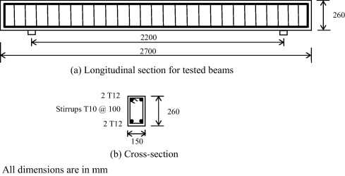
In this study, the test program includes casting, instrumentation, and testing six RC beams having a rectangular cross-section. The cross section of all beams was 260 mm depth and 150 mm width. The overall length of all beams was 2700 mm whereas the beam span was 2200 mm. the same steel reinforcement was provided for all tested beams; the flexural reinforcement consisted of two 12-mm diameter steel bars as bottom reinforcement and two 12-mm diameter steel bars as top reinforcement. For shear reinforcement; 10 mm diameter stirrups with spacing 100 mm were used throughout the entire beam length. The thickness of the concrete cover was 25 mm at the lateral and upper faces of the beam and 35 mm at the bottom side. The dimensions and details of the tested beams are summarized in Fig. 1.
|
|
|
Figure 1. Dimensions and reinforcement details for tested beam specimens. |
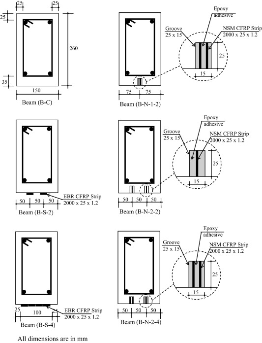
The CFRP strips used have a width of 50 mm and a thickness of 1.2 mm. In order to insert the strip through the concrete cover, the strips were cut into two halves each had a 25 mm width.
The ultimate tensile strength and modulus of elasticity of the CFRP strips used are 2800 MPa and 165 GPa, respectively as given in the manufacturer technical data sheet (Sika Egypt). The adhesive used to adhere the strips was two component epoxy resin, selected fine-grain aggregates and special additives mixed according to the instructions of the manufacturer. The mechanical properties of the materials used for tested beams are listed in Table 1. Many variables were considered in the experimental program such as: (a) FRP amount (i.e., two strips or four strips); (b) FRP distribution (i.e., using one grove or two groves); and (c) Laminate applications technique (i.e., NSM technique or EBR technique).
| Material | Dimensions (mm) | Yield point (MPa) | Compressive strength (MPa) | Ultimate tensile strength (MPa) | Modulus of elasticity (GPa) |
|---|---|---|---|---|---|
| Concrete | – | – | 35 | – | 28 |
| Steel reinforcement | D = 12 | 400 | – | 600 | 200 |
| D = 10 | 350 | – | 520 | 200 | |
| CFRP strips | t = 1.2 | – | – | 2800 | 165 |
2.2. Strengthening configuration
The strengthening schemes for tested beams are presented in Fig. 2. Beam B-C was tested in its original condition without strengthening and therefore it is considered as the control beam. Three beams were strengthened with NSM CFRP strips and were tested to investigate their performance and modes of failure. The installation of the NSM strips started by cutting slits of about 25 mm depth and 25 mm width through the concrete cover of the beams using a diamond blade cutter. Pressurized air was then used to remove the dust from the grooves to ensure a better adherence between the concrete surface and the CFRP strips. Following that, each groove was filled with epoxy adhesive and then the CFRP strip was inserted into the groove and was pressed so the adhesive is forced to completely fill the space between the strip and the sides of the groove. The surface was then leveled and the excess adhesive was removed. Beam B-N-1-2 was strengthened using two NSM CFRP strips installed into one groove whereas Beam B-N-2-2 was strengthened using two NSM CFRP strips installed into two grooves (i.e., one strip in each groove). Beam B-N-2-4 was strengthened using four NSM CFRP strips installed into two grooves (i.e., two strips in each groove). All Beams had the same strip dimensions and the same groove size. Furthermore, two beams were strengthened using EBR CFRP strips. Beam B-S-2 was strengthened using two EBR CFRP strips whereas Beam B-S-4 was strengthened using four EBR CFRP strips.
|
|
|
Figure 2. Details of tested RC beams. |
2.3. Test setup and instrumentation
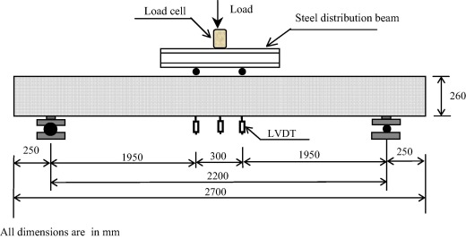
All beams were simply supported and were tested to failure under the effect of four point loads. A hydraulic jack of 1000 kN capacity was used to apply the load through a steel distribution beam as shown in Fig. 3.
|
|
|
Figure 3. Test setup. |
Three linear variable differential transformers (LVDTs) were used for all tested beams to monitor the mid-span deflection. For all beams strengthened with CFRP strips, strain gauges were attached to the CFRP strips at the mid length of the strips and oriented in the longitudinal direction to monitor CFRP strain. The load was applied incrementally up to failure of each beam. At every load increment, the propagation of cracks was observed and was marked. The deflections and strains were recorded using a data acquisition system.
2.4. Test results and discussions
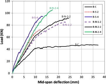
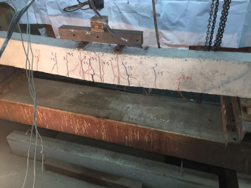
The performance and the effectiveness of NSM technique in enhancing the flexural strength of the RC beams were compared to those of the EBR technique. The effects of strips distribution (one groove versus two grooves), and the CFRP amount are presented. A summary of test results for all tested beams is presented in Table 2. The test results in terms of the relationship between the applied load and the mid-span deflection for all tested beams are shown in Fig. 4. The control beam B-C failed at a load of 47.03 kN by concrete crushing after yielding of steel reinforcement. The formation of the cracks followed a typical crack pattern of flexural members as shown in Fig. 5. The first visible crack was observed at the mid span at a total load of about 10 kN. By increasing the loads, new flexural cracks started to form and uniformly distributed along the full length of the beam. The crack width increased with increasing the load up to the beam failure.
| Specimen | Strengthening scheme | Test results | ||||||
|---|---|---|---|---|---|---|---|---|
| No. of grooves | No. of strips in each groove | Total no. of strips | Total area of CFRP (mm2) | Maximum CFRP strain measured at the ultimate load (mm/mm) | Maximum mid-span deflection at the ultimate load (mm) | Total applied load at failure Pt (kN) | CFRP strengthening effectiveness ratioa (%) | |
| B-C | N/A | N/A | N/A | – | – | 36.64 | 47.03 | – |
| B-S-2 | N/A | N/A | 2 | 60 | 0.0048 | 12.25 | 72.26 | 54 |
| B-S-4 | N/A | N/A | 4 | 120 | 0.0048 | 13.21 | 94.57 | 101 |
| B-N-1-2 | 1 | 2 | 2 | 60 | 0.0097 | 22.55 | 85.25 | 81 |
| B-N-2-2 | 2 | 1 | 2 | 60 | 0.0128 | 24.50 | 91.57 | 95 |
| B-N-2-4 | 2 | 2 | 4 | 120 | 0.0059 | 17.35 | 105.56 | 125 |
a. Strengthening effectiveness ration = (failure load of the beam − failure load of the control beam)/failure load of the control beam.
|
|
|
Figure 4. Load versus mid-span deflection for tested beams. |
|
|
|
Figure 5. Crack pattern at failure for the control beam B-C. |
All strengthened beams showed similar behavior as that observed for the control beam up to cracking. After cracking, the load deflection relationship of beams strengthened with NSM CFRP strips was almost similar to that for beams strengthened with EBR CFRP strips.
For beam B-S-2 strengthened with two EBR CFRP strips, firstly vertical flexural cracks were observed at the mid-span when the applied load reached about 15 kN. With further increase in the load, the cracks continued to widen but the presence of CFRP reinforcement controlled the crack width in comparison with the control beam. The failure occurred at a total applied load of 72.26 kN by debonding of CFRP strips at the strip–epoxy interface. The debonding started from mid-span and was followed by concrete crushing as shown in Fig. 6. It should be noted that strengthening beam B-S-2 using two EBR CFRP strips resulted in a 54% increase in the ultimate load in comparison with that of the un-strengthened control beam. The maximum measured FRP strain was 0.0048 mm/mm, which represents about 28% of the ultimate strain of the CFRP. This value is not absolute because it depends on the location of the strain gauges with respect to the cracks.
|
|
|
Figure 6. Cracking pattern and debonding of CFRP strips at failure for beam B-S-2. |
In the case of beam B-S-4 strengthened with four EBR CFRP strips, the formation and propagation of cracks were similar to those of beam B-S-2. The failure occurred due to debonding at the strip-epoxy and the epoxy–concrete interfaces starting from mid-span as shown in Fig. 7. It was followed by concrete crushing at a load of 94.57 kN. Strengthening Beam B-S-4 with four EBR CFRP strips resulted in a 101% increase in the ultimate load in comparison with that of the control beam. The maximum recorded CFRP strain was 0.0048 mm/mm and represents 28% of the ultimate strain of the CFRP. Comparing the results of testing Beam B-S-4 to those of testing beam B-S-2, the amount of CFRP used to strengthen beam B-S-4 was greater than that used for beam B-S-2 by 100%. However, only a 31% increase in the ultimate load was obtained. This means that there is an optimum amount of FRP, beyond which the strengthening effectiveness becomes questionable.
|
|
|
Figure 7. Cracking pattern and debonding of CFRP strips at failure for beam B-S-4. |
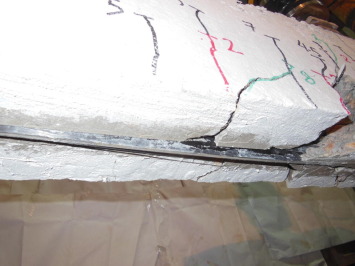
As a result of using NSM technique, a significant increase in the load carrying capacity was observed due to the high utilization of the bond strength of the CFRP reinforcement. In the case of beam B-N-1-2 strengthened with two CFRP strips in one groove, the maximum total applied load at failure was 85.25 kN, which is 81% and 18% higher than that of the control beam, B-C, and the beam strengthened with the same amount of CFRP in the form of two EBR CFRP strips, B-S-2, respectively. Therefore, the NSM strengthening technique using CFRP strips is more effective than the externally bonded one (EBR). It can be observed that the failure occurred at the interface between the epoxy adhesive and the concrete, as shown in Fig. 8. The maximum measured CFRP strain at failure was 0.0097 mm/mm, which represents 57% of the ultimate CFRP strain. It should be noted that the measured CFRP strain at failure for beam strengthened with NSM strips, beam B-N-1-2, was higher than that for beam strengthened with EBR strips, Beam B-S-2, by about 102%.
|
|
|
Figure 8. Ultimate failure of beam B-N-1-2. |
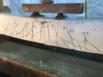
In case of beam B-N-2-2 strengthened with two NSM CFRP strips installed in two grooves (i.e., one strip in each groove), failure occurred by debonding at the epoxy–concrete interface near the maximum moment region after extensive cracking of the concrete at mid span as shown in Fig. 9. The maximum total applied load was 91.57 kN, which is 95% and 8% higher than that of the control beam, B-C, and that of beam B-N-1-2, respectively. It should be noted that beam B-N-2-2 was strengthened with the same amount of NSM CFRP as that for beam B-N-1-2 (i.e., two NSM CFRP strips) but the strips were inserted in two grooves instead of one. This resulted in an increase in the ultimate load due to effect of strips distribution. The maximum measured CFRP strain was 0.0128 mm/mm, which represents 75% of the ultimate strain of the CFRP.
|
|
|
Figure 9. Cracking pattern at failure for beam B-N-2-2. |
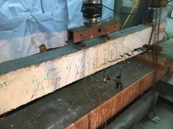
Among all tested beams, it was found that the ultimate load of beam B-N-2-4 was the highest. Such beam was strengthened using four NSM CFRP strips. The ultimate load in this case was 105.56 kN which is 125% higher than that of the control beams, B-C. When comparing the results of beams B-N-2-4 and B-S-4, the amount of CFRP used to strengthen beam B-N-2-4 was the same as that used for beam B-S-4. However, an increase in the load carrying capacity of 12% was obtained. This means that using the NSM flexural strengthening technique is more effective than the EBR technique. It should be noted that beam B-N-2-4 failed by peeling off of the CFRP strips together with the concrete cover as shown in Fig. 10. The maximum recorded CFRP strain at failure was 0.0059 mm/mm, which represents 35% of the ultimate CFRP strain.
|
|
|
Figure 10. Cracking pattern and peeling off of CFRP at failure for beam B-N-2-4. |
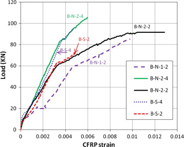
The load-CFRP strain relationships for tested beams are presented in Fig. 11. The maximum measured tensile strain was 0.0048 and 0.0128 for the EBR CFRP strips and the NSM CFRP strips, respectively. This means that EBR system did not utilize the full tensile strength of the CFRP strips in comparison with the NSM technique.
|
|
|
Figure 11. Load versus measured CFRP strain for tested beams. |
3. Design approach
In order to develop a design approach for the flexural members strengthened with NSM technique, the model of the moment capacity specified in the ACI 440.2R-08 [10] was adopted.
The moment capacity of the strengthened flexural member was expressed in the following form:
|
|
(1) |
where Mn is the nominal bending moment, As and Af are the cross sectional areas of the longitudinal steel reinforcement and FRP respectively, fs is the ultimate steel tensile stress, ffe is the effective ultimate tensile stress of the FRP, h is the total depth of the beam, ds is the effective depth of the steel reinforcement, c is the position of the neutral axis, and ψf = 0.85 is a safety factor, and β1 is an parameter given in Section 10.2.7.3 of ACI 318-02 [12]. However, the formulation for the effective strain level in the FRP at ultimate, εfe was expressed in the ACI 440.2R-08 [10] as follows:
|
|
(2) |
where ɛcu is the maximum acceptable concrete compressive strain (=0.003), df is the effective depth of FRP reinforcement, εbi is the initial strain of the concrete substrate, and εfd is the upper limit of the FRP strain level at which debonding may occur. This can be obtained from the following equation in the case of EBR:
|
|
(3) |
where is the specified compressive strength of concrete, n is the number of plies of FRP flexural reinforcement, tf is the thickness of the FRP material, Ef is the modulus of elasticity of FRP materials, and εfu is the FRP rupture strain.
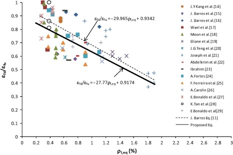
For the NSM technique, the ACI 440.2R-08 [10] has indicated that the value of εfd may vary from 0.6 εfu to 0.9 εfu depending on many factors such as member dimensions, steel and FRP reinforcement ratio, and surface roughness [13] and [14] and recommended using εfd = 0.7 εfu. Moreover, the analysis found in the available researches for flexural members strengthened with NSM technique indicates that εfd/εfu decreases with the increase of the equivalent reinforcement ratio, ρl,eq[15], that can be obtained from the following equation:
|
|
(4) |
where b is the beam width, and Es is the Young’s modulus of the steel reinforcement. The relationship of the εfd/εfu, and ρl,eq has been proposed by Barros and Kotynia [11] and was taken from the analysis of the experimental results of beams and slabs strengthened with NSM strips. This relationship has been represented by the following equation:
|
|
(5) |
In this study, modifications are proposed to improve the Equation proposed by Barros and Kotynia [11] to include results of new tests of beams and slabs strengthened with NSM strips.
The proposed modified relationship of εfd/εfu and ρl,eq was calibrated using the available 60 test results, shown in Fig. 12[14], [15], [16], [17], [18], [19], [20], [21], [22], [23], [24], [25], [26], [27], [28] and [29]. It can be observed from the results presented that there is a tendency for a decrease of εfd/εfu with the increase of ρl,eq. The relationship was established and is expressed as follows:
|
|
(6) |
|
|
|
Figure 12. Relationship between εfd/εfu and the equivalent reinforcement ratio ρl,eq. |
The value of εfd obtained from the above Equation may be used in the design scheme of ACI 440.2R-08 [10] as an upper limit of strain in the FRP at ultimate load instead of the constant value of 0.7 εfu.
Moreover, the available researches also indicate that εfd/εfu decreases with a decrease in the distance of the FRP strip to the edges of the beam and with a decrease in the distance between FRP strips [14] and [15]. Furthermore, the geometry of the slit and the properties of the adhesive materials may also have some influence on the value of the εfd/εfu ratio. However, insufficient research results are available to perform a quantitative estimate of the influence of these variables on the variation of the εfd/εfu ratio.
3.1. Comparison between test results and those obtained from proposed equation
The comparison between the calculated values of εfe/εfu estimated from the ACI 440.2R-08 [10] equations for tested beams B-N-1-2, B-N-2-2, and B-N-2-4 and the upper proposed limit of εfd/εfu (Eq. (6)) is presented in Table 3. The comparison indicates that the proposed equation for the upper limit of εfd/εfu gives conservative results for tested beams in comparison with the experimental results.
| Specimen | Experimental results | Calculated value of εfe/εfu | Proposed equation for the upper limit of εfd/εu Eq. (6) | |
|---|---|---|---|---|
| Total applied load at ultimate Pt (kN) | Applied bending moment at ultimate Mu (kN m) | |||
| B-N-1-2 | 85.25 | 40.5 | 0.593 | 0.69 |
| B-N-2-2 | 91.57 | 43.49 | 0.68 | 0.69 |
| B-N-2-4 | 105.56 | 50.14 | 0.44 | 0.65 |
4. Conclusions and recommendations for future research
An experimental investigation was conducted in order to compare and to evaluate the performance and effectiveness of the NSM and EBR techniques for the flexural strengthening of RC beams. Six beams were casted and tested through the experimental program. A design approach for flexural members strengthened with NSM technique was developed using the moment capacity model specified in the ACI 440.2R-08 [10].
Based on this study, the following conclusions can be drawn:
- The ultimate load carrying capacity of beams strengthened with NSM CFRP strips was higher than that for beams strengthened with EBR CFRP strips having the same amount of CFRP materials with a percentage ranged from 12% to 18%. This is due to the higher bond strength of the CFRP strips in the case of NSM technique. The NSM CFRP strips have double the bonding area compared with the EBR CFRP strips.
- Increasing the amount of CFRP strips not necessarily results in a proportional increase in the flexural capacity of the RC member especially if debonding of CFRP strips controls the failure.
- Using the same amount of NSM CFRP Strips, and distributing the strips in two grooves instead of one leads to a significant reduction in the crack widths and an increase in the ultimate load.
- Failure of beams strengthened with EBR CFRP strips is controlled by debonding at the strip–epoxy or the epoxy–concrete interfaces.
- For beams strengthened with NSM CFRP strips, failure is controlled by debonding of CFRP strips and peeling off of the CFRP strips together with the concrete cover.
- The suggested design approach may be used efficiently for computing the moment capacity of RC flexural members strengthened with NSM CFRP strips.
Recommendations for future research are as follows:
- It is recommended to consider the following for future research:
- A wider experimental database is needed to confirm the trends indicated by the present study.
- Some parameters that may affect the performance of NSM FRP technique such as the edge distance, the distance between two adjacent slits, the geometry of the slit, the properties of the adhesive materials, and the thickness of the adhesive layers, should be investigated.
Acknowledgment
The test program presented in this study was carried out at the Reinforced Concrete Laboratory of the Structural Engineering Department at the Faculty of Engineering – Alexandria University. Thanks are due to all of the laboratory’s staff for their assistance throughout the test program.
References
- [1] M. Arduini, A. Di Tommaso, A. Nanni; Parametric study of beams with externally bonded FRP reinforcement; ACI Struct. J., 94 (5) (1997), pp. 493–501
- [2] A. Morsy, K. Helmy, N. El-Ashkar, M. Nada, Flexural strengthening for R.C beams using CFRP sheets with different bonding, in: International Conference on Advanced in Structural and Geotechnical Engineering (ICASGE’15), Hurghada, Egypt, April 2015, 13 pp.
- [3] Raafat El-Hacha, Sami Rizkalla; Near-surface-mounted fiber-reinforced polymer reinforcements for flexural strengthening of concrete structures; ACI Struct. J., 101 (5) (2014), pp. 717–726
- [4] Slobodan Rankovie, Radomir Folic, Marina Mijalkovie; Effects of RC beams reinforcement using near surface mounted reinforcement FRP composites; Facta Univ., Ser. A & CE, 8 (2) (2010), pp. 177–185
- [5] L. De Lorenzis, J.G. Teng; Near-surface mounted FRP reinforcement: an emerging technique for strengthening structures; Composites Part B, 38 (2007), pp. 119–143
- [6] Tarek Hassan, Sami rizkalla; Investigation of bond in concrete structures strengthened with near surface mounted carbon fiber reinforced polymer strips; J. Compos. Constr., ASCE (2003), pp. 248–257
- [7] Paul Ciobanu, Nicolae Taranu, Sergiu Popoaei, Dragos Banu, Structural response of reinforced concrete beams strengthened in flexural with near surface mounted fiber reinforced polymer reinforcement experimental setup, Technical University of Iasi, Faculty of Civil Engineering and Services, LVIII(LXII), Fasc. 4, 2012, 8 pp.
- [8] A.A Khalil, E.E. Etman, A.H.EL-Masry, Behavior of reinforced concrete continuous beams strengthened with near surface mounted reinforcement, in: International Conference on Advanced in Structural and Geotechnical Engineering, ICASGE15, 6–9 April 2015, Hurghada, Egypt, 17 pp.
- [9] Fib – Bulletin 14, Externally Bonded FRP Reinforcement for RC Structures, Technical report by Task Group 9.3 FRP (Fiber Reinforced Polymer) reinforcement for concrete structures, Féderation Internationale du Béton – fib, July 2001, 130 pp.
- [10] ACI Committee 440, Guide for the Design and Construction of Externally Bonded FRP Systems for Strengthening Concrete Structures (440.2R-08), American Concrete Institute, 2008, 76 pp.
- [11] J.A.O. Barros, R. Kotynia, Possibility and challenges of NSM for the flexural strengthening of RC structures, in: Fourth International Conference on FRP Composites in Civil Engineering (CICE 2008), 22–24 July 2008, Zurich, Switzerland, 6 pp.
- [12] ACI Committee 318, building Code Requirements for Structural Concrete (ACI 318–02) and Commentary (ACI 318R-02), American Concrete Institute, Detroit, 2002, 369 pp.
- [13] Renato Parretti, Antonio Nanni; Strengthening of RC members using near-surface mounted FRP composites: design overview; Adv. Struct. Eng., 7 (5) (2004)
- [14] J.Y. Kang, Y.H. Park, J.S. Park, Y.J. You, W.T. Jung, Analytical evaluation of RC beams strengthened with near surface mounted CFRP laminates, in: 7th International Symposium, Fiber Reinforced Polymer Reinforcement for Concrete Structures (FRPRCS7), Kansas City, 2005, pp. 779–794.
- [15] J.A.O. Barros, S.J.E. Dias, J.L.T. Lima; Efficacy of CFRP-based techniques for the flexural and shear strengthening of concrete beams; J. Cem. Concr. Compos., 29 (2007), pp. 203–217
- [16] J.A.O. Barros, A.S. Fortes; Flexural strengthening of concrete beams with CFRP laminates bonded into slits; J. Cem. Concr. Compos., 27 (4) (2005), pp. 471–480
- [17] Wael Ibrahim, Waleed A. Fattah, Azza Kotb, Mostafa A. Mjeed, Flexural behavior of RC beams strengthened with CFRP strips, in: The 7th International Conference on FRP Composites in Civil Engineering, CICE 2014, August 20–22, Vancouver, Canda, 2014, 6 pp.
- [18] Do Young Moon, Hong Seob Oh, Goang Seup Zi; Assessment of flexural strengthening behavior using the stirrup-cutting near surface mounted (CNSM) CFRP strip; J. Korea Inst. Struct. Maint. Inspect., 16 (6) (2012), pp. 102–112
- [19] Eliane K. Castro, Guilherme S. Melo, Yosiaki Nagato, Flexural Strengthening of RC “T” Beams with Near Surface Mounted (NSM) FRP Reinforcement, July 16–18, FRPRCS-8 University of Patras, Patrace, Greece, 2007, 10 pp.
- [20] J.G. Teng, L. De lorenzis, Bo wang, Rong Li, T.N. wong, Lik Lam; Debonding failures of RC beams strengthened with near surface mounted CFRP strips; J. Compos. Constr., ASCE. (2005), pp. 92–105
- [21] Joseph R. Yost, Shawn P. Gross, David W. Dinehart, Jason J. Mildenberg; Flexural behavior of concrete beams strengthened with near-surface-mounted CFRP strips; ACI Struct. J., 104 (4) (2007), pp. 430–437
- [22] Abdelkrim Laraba, Abdelghani Merdas, Naser-Eddine Chikh, Structural performance of RC beams strengthened with NSM-CFRP, in: Proceeding of the World Congress on Engineering, vol. II, London, U.K., 2014, pp. 978–988.
- [23] Ibrahim Attia Sharaky, A study of the bond and Flexural behavior of Reinforced Concrete Elements Strengthened with Near Surface Mounted FRP Reinforcement, PhD Thesis, University of Girona, Spain, 2013, 263 pp.
- [24] A.S. Fortes, NSM for Flexural Strengthening of RC Structures, PhD Thesis, University of Santa Catarina, Brazil, May 2003, 213 pp.
- [25] F.T.S. Ferreira, J.A.O. Barros, Fatigue Behavior of NSM Strengthened RC Beams Failing in Bending, Report 06-DEC/E-10, Civil Eng. Dept., University of Minho, 2006.
- [26] A. Carolin, Carbon Fiber Reinforced Polymers for strengthening of Structural Elements, PhD Thesis, Lulea University of Technology, 2003.
- [27] E. Bonaldo, J.A.O. Barros, P.B. Lourenço, Steel Fiber Reinforced and Laminate Strips for High Effective Flexural Strengthening of RC Slabs, Report 05-DEC/E-14, Civil Eng. Depart., University of Minho, Portugal, 2005.
- [28] K. Tan, G. Tumialan, A. Nanni, Evaluation of CFRP Systems for the Strengthening of RC Slabs, CIES 02 38, Final Report, University of Missouri Rolla, 2002, 120 pp.
- [29] E. Bonaldo, J.A.O. Barros, P.B. Lourenco, Concrete Slabs Reinforced with Epoxy-Bonded Carbon Laminates Into Slits, International Conference on Construction Materials, 3. Vancounver, Canada, 2005, 11 pp.
Document information
Published on 12/04/17
Licence: Other
Share this document
Keywords
claim authorship
Are you one of the authors of this document?
