Abstract
This work presents the development of two free Graphical User Interfaces (GUI), called FASTLognoter and MorisonForm, both focused on the analysis of the behaviour of offshore structures, especially of offshore wind turbines. The first one is related to the aeroelastic analysis of wind turbines, and the second is concerned with the seakeeping of marine structures. The development of these tools has been carried out using a powerful software called Lognoter. This tool is free software for Knowledge Management in Technology (KMT), which integrates computer programming for allowing the development of GUIs. These GUIs give an open platform for conducting a parametric study of the structural and dynamic behaviour of marine structures. Their coupling permits the user to set a suitable way to evaluate new concepts in marine structures. Finally, an application for the intensive analysis of offshore wind turbines is shown.
1 Introduction
The increase in developments in the field of large offshore structures (Offshore Wind Turbines, OWT, for instance), requires a precise study of their dynamic behaviour. The sea constitutes an aggressive environment for offshore installations and the behaviour of these structures includes several phenomena, which makes it harder to study the structural response of marine devices. Due to the high cost of offshore wind technology, numerous countries recently started a challenge to find the best suitable support platform for OWT in renewable energy industries (Tong 1988, Sclavounos, Butterfield, et al. 2005, Breton and Moe 2009). The current fixed bottom technology has probably reached a limit, but both cost reduction and deep-water technology constitute the main way to favour the proliferation of this technology. Since the field is wide and involves different aspects (wind resource estimation, platform design, structural response, soil studies, etcetera), ambitious software is required. So, tool integration, parametric design and optimization can be considered as key issues for researchers, scientists and engineers, in order to obtain suitable solutions. In a brief literature survey, numerous works related to this problem in several fields can be found (Tracy 2007, Collu, Brennan, et al. 2012, Seebai and Sundaravadivelu 2013, Kaiser and Snyder 2014, Passon and Branner 2014).
1.1 Simulation tools for OWT
In the offshore wind industry, some interesting computer codes can be found for simulating appropriately a wind turbine, as well as for determining the behaviour and the optimizing of marine structures. Most of them are not free, and others are free available but are complex, such as Computer Aided Engineering Tools (CAE) offered by the National Renewable Energy Laboratory, NREL (www.wind.nrel.gov/designcodes), which permits engineers to make a complete study of both onshore and offshore wind turbines.
In the first group, different commercial codes can be found. GH-Bladed (GL Garrad-Hassan, www.gl-garradhassan.com) allows a complete calculation of OWT systems. Other codes are SamCEF (Samtech, www.samtech.com), SIM-PACK (Simpack, www.simpack.com), SIMO/RIFLEX/HAWC2 (Marintek, www.sintef.no/home/MARINTEK), or WAMIT (Massachusetts Institute of Technology, MIT, www.wamit.com), which is one of the most advanced tools for analysing wave-structure interaction. Finally, SeaFEM (CompassIS, www.compassis.com) can be regarded as a suite of tools for the computational analysis of the effect of waves, wind and currents on naval and offshore structures, and for manoeuvring studies (Borja and Garcia-Espinosa 2013).
Alternatively, free tools such as QBlade (University of Berlin, www.qblade.de.to) or toolkits for the analysis of rotor aerodynamics, aeroelastic or hydrodynamics, can be found. Perhaps the most relevant free available package is that offered by NREL, i.e., FAST/AeroDyn/HydroDyn package (Laino and Hansen 2002, Jonkman and Buhl 2005). This code allows a wide study of aero-hydrodynamics, including the structural response of all types of HAWTs (Horizontal Axis Wind Turbines). Recently, we have coupled the reference code FAST to Lognoter software (CompassIS, www.compassis.com), giving a consistent GUI for management of the package (see Gutierrez, Zamora, et al. 2013), adding new features, and achieving a Design Optimization Tool (DOT). The new tool has been called FASTLognoter (Gutierrez, Zamora, et al. 2013), and has been developed with the aim of generating and providing an interface to help the user in the normal operation with FAST/AeroDyn/HydroDyn, as well as to facilitate the design optimization of wind turbines, focused mainly on offshore wind turbines.
1.2 The aim of this work
The purpose of this work is to provide a successful toolkit for the behaviour analysis of marine structures. Hence, the development of an open and free available platform for the rough estimation of the seakeeping of marine structures (especially OWT), using the features of Lognoter software (a free programmable platform), is presented. The developed tool, called MorisonForm, has been coupled with FASTLognoter to make a DOT for optimizing marine structures. FASTLognoter is related to complete calculations of aerodynamics and structural response of HAWTs, whereas MorisonForm is a GUI for calculating the forces exerted by waves on the support platforms and for analyzing their dynamic response. The features and capabilities of new GUIs are presented. The programming work is carried out using XML (Extensible Markup Language) and Tcl/Tk (Tool command language/Toolkit). Finally, an intensive analysis of different types of support platform for OWT using coupled calculation (i.e., linking the aerodynamic and the hydrodynamic studies), is presented.
2 Computer programming of GUIs
2.1 Programming approach
Regarding the programming approach, a detailed explanation of the capabilities of Lognoter is required, because the presented GUI has been developed by means of Lognoter forms. As explained above, Lognoter may be classified as a free available computer code (available on the website www.compassis.com) employed for the knowledge and information management of processes in the engineering field, for instance. Furthermore, Lognoter can be used for creating powerful forms and GUIs by means of the project Lognoter forms.
In brief, Lognoter has the following important features: database storage using, for instance, in-process library SQlite (www.sqlite.org); insertion of tables and pictures; embedding of links; adapted sight; back-up copy; database and page encryption; design and graphics creation tools; importation/exportation; mathematical utilities; synchronisation; easy page navigation, and finally the most important, the creation of GUIs.
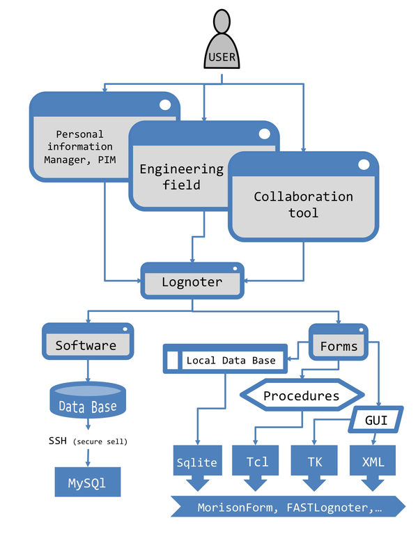
As already mentioned, the forms of Lognoter can be placed into project Lognoter forms (www.lognoter.com/c/lognoterforms). This is a website based on the wiki concept, whose main objective is the development of a site where developers and users can exchange forms, add tools, experiences, procedures, help, etcetera (Gutierrez, Zamora, et al. 2013). The users of the forms can download the presented GUIs and use them in an exhaustive manner, adding new functions according to new requirements. Advanced capacities, such as XML and Tcl/Tk programming, should be underlined, since the development of powerful tools and the extension of capabilities of GUIs can be conducted easily. Figure 1 shows how the user can use Lognoter as a collaboration tool in the engineering field; from Lognoter, the forms lead to obtaining tools such as MorisonForm or FASTLognoter, through the use of databases like SQlite, and Tcl, Tk or XML. Following this philosophy, Fig. 2 shows a screen example in MorisonForm GUI.
|
| Figure 1: Scheme showing the general approach of the software application. |
2.2 Editing Lognoter forms using XML programming
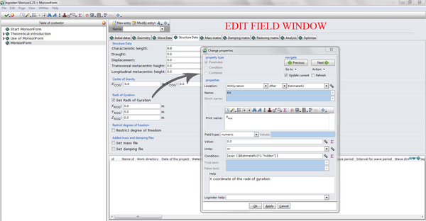
One of the most useful advantages of using Lognoter forms is the XML format for editing the GUIs. XML programming is an open and flexible standard derived from SGML (Standard Generalised Markup Language). It was designed to transport and store data (with focus on what data is), constitutes a W3C recommendation (World Wide Web Consortium, www.w3.org) and is endorsed by software market leaders. In Lognoter forms, the information is stored in plain text format. It can be viewed in all major browsers and is designed to be self-descriptive. The elements in a Lognoter GUI outline a tree-structure, starting at the root and progressing towards the leaves, through the branches, with different relationships between the nested elements. The XML elements are defined using fixed tags and can have attributes, which provide additional information about elements inserted into Lognoter form. Lognoter GUI also allows the user to edit and create new forms using its tools, avoiding programming editions. Figure 3 shows the option edit field on Lognoter GUI.

|
| Figure 2: Advanced capacities of Lognoter forms. Screen example taken from MorisonForm GUI. |
|
| Figure 3: Screen showing the edit field option on Lognoter GUI. |
2.3 Adding new functions and procedures using Tcl/Tk programming
Today, Tcl is considered an easy and dynamic programming language, suitable for innumerable uses, web and desktop applications, networking, administration or testing, for instance. Because it is a dynamic language, the resulting codes are shorter and faster to develop. These features make the Lognoter GUIs an open platform for adding new code easily. It is usually common to find facilities in most modern dynamic languages (objects, namespaces) to develop large applications, for instance, MorisonForm. Regarding Tk, this is a Graphical User Interface (GUI) toolkit. Tk may be a standard GUI for Tcl, but it is found in many other dynamic languages. In our case (see Fig. 2), the user can modify the code forming MorisonForm to add new functions. For example, the user may add functions to take into account new spectral density functions.
2.4 Handling the database of Lognoter forms
It is well known that when engineers use a computer code for analysing anything, a readily available database to store ongoing cases is often required. Lognoter employs several Application Programming Interface (API) of databases (for instance, MySQl or SQlite). SQlite (www.sqlite.org) is a representative in-process compact library, carefully tested, which implements a self-contained, serverless, zero-configuration and transactional SQL database engine. In addition, international leading companies have supported it. MorisonForm uses some routines in order to get the input data of a database for making the calculations. This feature allows the users a parametric calculation, since they can be stored cases, which vary in one or more parameters.
2.5 Generalization of the procedure
The explained methodology is versatile and it can be used for solving engineering problems. The generalized procedure can be summarized as:
- Setting the problem statement. For example, the basic equations, the needed inputs, and the required results should be stated.
- Setting the GUIs design plan. The information required per page, the buttons and entries, and any other details, should be conducted through the capabilities and features of Lognoter.
- Programming the GUI. The users can get code source from other GUIs uploaded into Lognoter forms webpage, or implement their own programming.
3 The MorisonForm GUI
The aim of the MorisonForm tool is to set a free available code capable of making an approximate assessment of the dynamic behaviour of floating structures composed mainly by slender elements in frequency domain approach. The forces exerted by linear waves are calculated using Morison's formulation (Morison, O'Brien, et al. 1950) and GUI solves the resulting linear systems. The tool outputs are the Response Amplitude Operators (RAOs) of the structure for different degrees of freedom, the computed loads and moments, natural frequencies, and standard deviations of the motions, always assuming that the OWT device is a linear system (Faltinsen 1990, Newman 1962).
3.1 Summary of linearized analysis of OWT in frequency domain
A typical form of the response equation of free floating OWT in frequency domain with a rigid wind turbine placed above it, including six degrees of freedom for steady state sinusoidal motions, can be written as
|
where , and are matrices of platform added mass, inertia, and wind turbine masses, respectively. On the other hand, and are platform and wind turbine damping. In addition, , and are hydrostatic restoring terms, restoring the effects of mooring systems, and restoring matrix for wind turbine, respectively. Finally, are complex amplitudes for existing forces and moments exerted on body (Faltinsen 1990, Newman 1962). Each term of the last matrices (inertia of the platform, restoring and radiation terms) are completely described in the literature (Bertram 2000, Lewis 1989, Jonkman 2007, for instance).
The flow passing around a slender element is considered a key problem of hydrodynamics on offshore structures. The forces exerted by surface waves on a slender body in an unsteady viscous flow may be determined by Morison's equations (Morison, O'Brien, et al. 1950). The forces are made up of three components named drag forces (generated by normal component of the flow velocity), inertia forces (generated by normal component of the flow acceleration), and lift forces (oriented normal to the velocity vector and normal to the axis of the slender element). MorisonForm takes into account this formulation to estimate the forces exerted on the support platform.
If members of the structure are considered circular or similar, the lift forces are not considered in the calculus. The total linearized forces acting on the slender element can be expressed as (Gran 1992)
|
|
(2) |
being a unit vector with directional cosines, a local fluid velocity vector, a local fluid acceleration vector, the diameter of the slender element, the transversal area of the body, and the water density. Finally, and are the drag and inertia coefficients, respectively. There are several limitations to Eq. (2), since it does not consider the influence of the adjacent section's flow and does not take into account the piercing phenomena. Note that velocity and acceleration vectors are then rotating 90 degrees out of phase with each other.
The presented tool evaluates some of these matrices (inertia, mooring, and loads) to solve the coupled equations. The rest of the terms are estimated using FASTLognoter tool. Codes to evaluate the added mass and radiation terms are also required; for instance, WAMIT or SeaFEM may be a suitable tool to get them. Equation (1) can be solved by substituting
|
|
(3) |
which leads to obtaining six coupled algebraic equations for real and imaginary parts, which can be solved by standard methods. This procedure is implemented in MorisonForm GUI. Thus,
|
|
(4) |
where is a vector column that contains the response of the OWT device. So, the transfer functions of OWT for translational modes (surge, sway and heave) are expressed as
|
|
(5) |
and rotational modes (roll, pitch and yaw),
|
|
(6) |
where is the characteristic length of the floating platform.
3.2 Main features of MorisonForm code
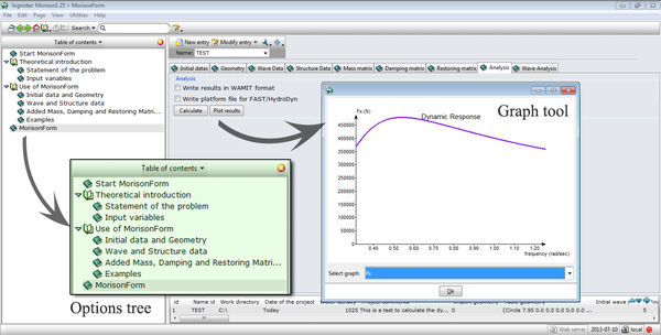
MorisonForm is developed using Lognoter and employing the advanced features of this tool; that is to say, Tcl/Tk, XML and a database such as SQlite computer programming. This allows the addition of a database with the tubular elements that form the structure. The tool can classify different types of project and sea conditions. To give the user more information about the software management, theory introduction and several explanations are included in an options tree, as well as dynamic help and adapted sight. The results can be exported to a compatible format with data processing programs, and can be plotted through Tk tool added into GUI (see Fig. 4).
|
| Figure 4: MorisonForm GUI. |
Regarding other features of the presented GUI, those exposed above for Lognoter forms can be underlined. The GUI is divided into pages related to specific parameters of the calculus (see Fig. 5). These pages are the following:
- Initial data. Here, the basic data related to the working directory or project date, for instance, are established.
- Geometry. The data related to geometry are inserted on this page.
- Wave data. The user can set the interval of the wave period for analysis, currents, specific values of drag and inertia coefficients, roughness of slender elements, wave direction, depth, and so on.
- Structure data. This page leads to establishing the main characteristics of the platform, such as position of centre of gravity, draught, radii of gyrations, transversal and longitudinal height of metacentre, etcetera.
- Mass matrix. The user can set the values of added mass of the platform (in a list form) or additional masses (for instance, the wind turbine mass matrix).
- Damping matrix. As on the preceding page, the user can insert the values of radiation problem (in a list form) or additional values (for instance, the structural damping of the wind turbine).
- Restoring matrix. The additional restoring term can be inserted on this page. MorisonForm also includes the possibility of calculating the linear effects of the mooring system.
- Analysis. Here, the buttons for carrying out the analysis and plotting the results are placed.
- Wave analysis. The variance of the motion for different spectral density of the ambient waves can be evaluated in this section.

|
| Figure 5: Page distribution of MorisonForm. |
MorisonForm includes the capability of adding mooring effects into restoring terms. The user can insert catenary or taut lines, and also spread mooring lines. Note that these terms are static and only give the user a rough approximation about the effects into the behaviour of the OWT devices (Faltinsen 1990). In additon, use of presented GUI leads to obtaining the variance of the motion, using different spectral models, such as Pierson-Mostkowitz or JONSWAP (Gran 1992). Finally, one of the most advanced features of the GUIs is the capability of modifying, adding or removing code from the form. Therefore, the user can edit the form and add code easily. This fact achieves the feature improvement of the forms, making the GUI a powerful tool; besides, the tool can be adapted to several projects and subjects.
3.3 Coupling between MorisonForm and FASTLognoter
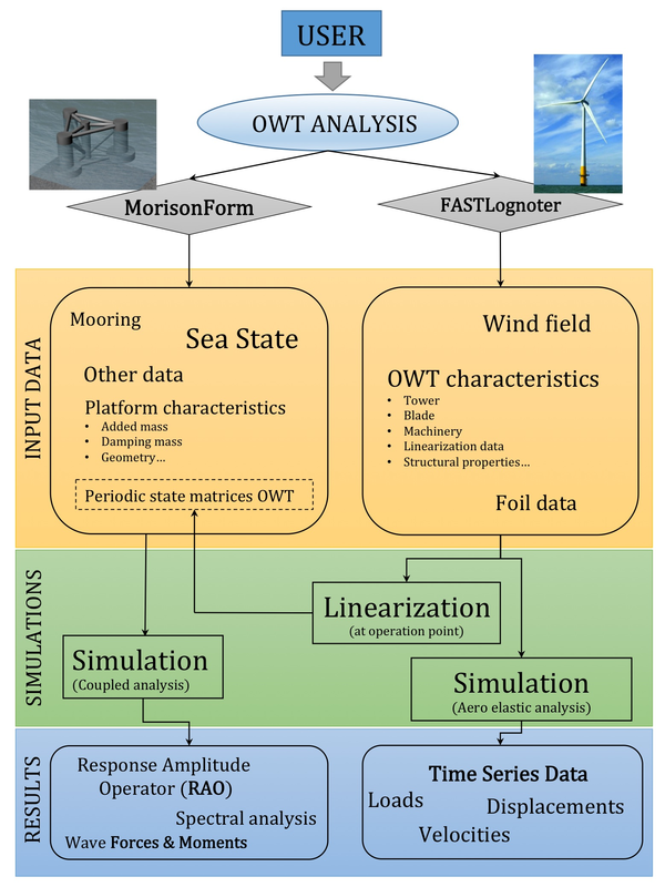
In order to analyze the dynamic behaviour of offshore structures, coupling between hydrodynamics, aerodynamics and mooring effects is required. Obviously, several complex effects can be found in OWT devices, and this fact makes it harder to do a complete study of marine structures. So, the aim of the MorisonForm development is to get a rough estimation of the dynamics of OWT, as previously explained. The preliminary idea concerning the coupling between the presented GUI and FASTLognoter is outlined in Fig. 6. FASTLognoter allows the linearization of the wind turbine, using FAST code, at the operation point. The results of the linearization are periodic state matrices, which can be added into MorisonForm GUI; then, the user can conduct an appropriate coupled analysis of the OWT in working operation.
|
| Figure 6: Preliminary idea of coupling with FASTLognoter. |
Most of the data may be estimated using the pre-processors added into FASTLognoter GUI. Thus, MorisonForm acts when the user has obtained the periodic state matrix. Finally, the user can calculate the forces and moments exerted by wave loads, and the transfer functions of the OWT device, i.e., Response Amplitude Operators (RAOs), which are key elements in the study of the behaviour of marine structures.
4 Discussion of results
4.1 Background
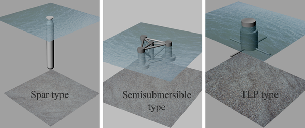
In order to illustrate the use of the presented GUIs, a study of different types of OWT platform is chosen as a powerful application. The seakeeping analysis for three representative kinds of typical platform design (see Fig. 7) for FOWT (Flotating Offshore Wind Tubine) is carried out, assuming the marine wind turbines are under steady-state operating conditions. The study is mandatorily coupled, that is, both the aerodynamic and the hydrodynamic effects are included and linked. FASTLognoter (Gutiérrez, Zamora, et al. 2013) is employed for calculating the linear representation of a given wind turbine (NREL baseline 5 MW, Jonkman, Butterfield, et al. 2009), whereas WAMIT (www.wamit.com) or SeaFEM (www.compassis.com) are used to get the added mass and radiation terms of the FOWT. Typical results are the RAOs of the structures studied for different degrees of freedom, which leads to systematic comparisons between the behaviour of devices.
|
| Figure 7: Different types of analysed platforms. |
4.2 Dynamic analysis of FOWTs and validation
The features of MorisonForm are presented by means of coupled studies for three representative OWT devices (Fig. 7). As a preliminary matter, two of them are platforms used in Offshore Code Comparison Collaboration (www.ieawind.org, OC3 and OC4 Projects); the aim of these collaboration projects is to carry out comparisons between different codes focused on the analysis of OWT. In fact, the Offshore Code Comparison Collaboration establishes a suite of benchmark simulations to survey and test new computer codes, new methodologies in the analysis of OWT, identify further research, and develop new concepts for OWT technologies.
The first analysed OWT platform is based on the OC3-Hywind Spar Buoy concept (a ballast stabilised type). This structure can be considered the world's first operational deepwater platform (owned by the Norwegian company StatoilHydro, constructed by Siemens Wind Power), in the North Sea off Norway (Jonkman 2007, Jonkman 2010, Jonkman and Matha 2011). The second OWT device uses a Tension Leg Platform (TLP) developed by MIT/NREL (Matha 2010) (a mooring stabilised platform). The last considered platform is a semisubmersible platform based on the OC4 Project Phase II (DeepCWind concept, a buoyancy stabilised type, Coulling 2013; Robertson, Jonkman et al. 2014). The main characteristics of the platforms can be found in Table 1. Firstly, the Spar Buoy and semisubmersible platforms are assumed as no-wind conditions. Secondly, the TLP platform is considered under steady-state operating conditions, coupling both the aerodynamic and the hydrodynamic effects, which are included and linked.
| Platform characteristics | OC3 | OC4 | NREL/MIT TLP |
| Diameter (m) | |||
| Draft (m) | |||
| Depth (m) | |||
| Water displacement (m) | |||
| Mass, including ballast (kg) | |||
| CM location below SWL1 (m) | |||
| Roll inertia about CM (kg.m) | |||
| Pitch inertia about CM (kg.m) | |||
| Yaw inertia about CM (kg.m) | |||
| Number of mooring lines | (4 pairs) | ||
| Unstretched line length (m) | |||
| Line diameter (m) | |||
| Line mass density (Kg.m) | |||
| Line extensional stiffness (N) |
(1) Still water level
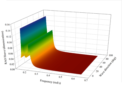
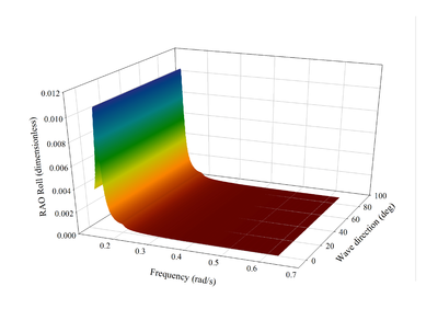
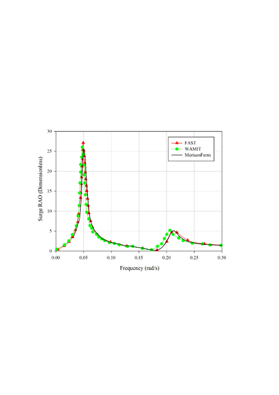
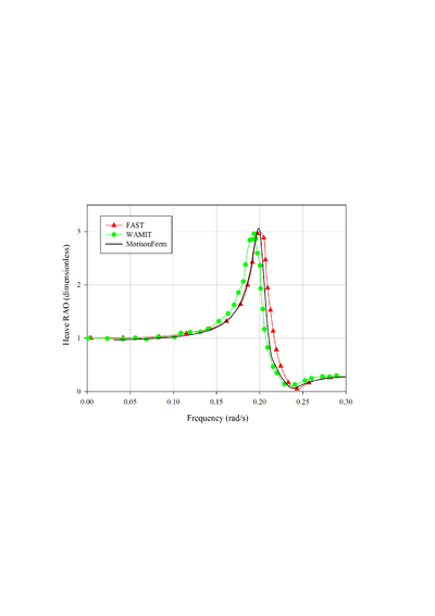
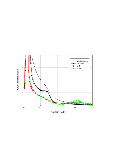
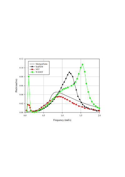
The dynamic analysis if FOWTs is carried out through the RAOs obtained as a function of the frequency of waves, as weel as with the corresponding natural frequencies (Table 2). RAO curves are shown for surge, heave and pitch movements for the OC3 Spar-Hywind and the TLP MIT/NREL design in Figs. 8 and 9, respectively. Then, RAO curves of surge and pitch for the OC4 semisubmersible platform is presented in Fig. 10
| Platform characteristics | OC3 | OC4 | NREL/MIT TLP |
| Surge | |||
| Sway | |||
| Heave | |||
| Roll | |||
| Pitch | |||
| Yaw |
|
|

|
| Figure 8: Response Amplitude Operators (RAOs) for a) surge, b) heave and c) pitch, for a OC3 Spar-Hywind platform. | ||
|
|

|
| Figure 9: Response Amplitude Operators (RAOs) for a) surge, b) heave and c) pitch, for a TLP MIT/NREL platform. | ||
|
|
| Figure 10: Response Amplitude Operators (RAOs) for a) surge and b) pitch, for a OC4 semisubmersible platform. | |
As explained, FASTLognoter GUI is used for coupling linearized wind turbine effects with seakeeping of floating structures under regular waves (Gutierrez, Zamora, et al. 2013). Regarding the results obtained with MorisonForm, the trends for RAOs presented in Fig. 8 for the OC3 Spar-Hywind, are consistent with those found in the literature (Ramachandran, Robertson, et al. 2013). This figure shows a comparison between the results obtained for the surge, heave and pitch RAOs with FASTLognoter, and those obtained with the HydroDyn module of FAST, as well as through WAMIT; it can be observed that the agreement of the results is good. Figure 9 shows the results obtained for TLP MIT/NREL platform, compared to those taken from literature (MIT, Matha 2010, WAMIT and SeaFEM). In this case, the trends of the results are similar, although some differences between the results from different sources can be found. Finally, Fig. 10 shows the comparison between the result obtained by means of MorisonForm and SeaFEM code (www.compassis.com), for the OC4 semisubmersible platform. Note that the agreement of the results for surge and pitch motions is excellent.
4.3 A note on preliminary design
In a brief discussion on the trends of the presented RAOs, the importance of the obtained results in a preliminary design must be noted. Wave frequencies in which the behaviour of the wind turbine does not perform properly should be identified. Obviously, decisions like the choice between one or other platform will depend on additional parameters, such as operability, ease of construction, transport maintenance, environmental impact and regulations, but at least, once the RAO curves are known, it is possible to determine the significant values for irregular seas for each degree of freedom, using the features of MorisonForm. Finally, it can be concluded that there is no clear winner for support platform between the studied OWT devices; this finding is a reflection of what happens in practice: different platforms are suitable for different operating conditions.
5 Concluding remarks
- The advanced capacities of Lognoter (a software used for computer programming of Graphical User Interfaces, GUI) are shown, with the aim of carrying out preliminary studies of Offshore Wind Turbine (OWT) devices.
- Computer programming with XML, a database such as SQlite, and Tcl/Tk is employed. The resulting software provides a suitable tool, called MorisonForm, for a rough estimation (in the frequency domain) of the behaviour under regular waves of floating structures, especially focused on OWT devices.
- MorisonForm tool is fully complemented with another tool described in a previous work, FASTLognoter (a GUI coupled to the reference code FAST, of NREL). The linking of MorisonForm with FASTLognoter enables the user to carry out a coupled analysis of floating offshore wind turbines.
- A key feature of the new toolkit presented is the capability of achieving parameterized studies and intensive analysis of OWT devices. The users can modify the code in an easy manner to improve its capabilities and add their own routines.
- Finally, an illustrative analysis has been conducted for three OWT samples. Although MorisonForm tool only allows this 'rough' estimation, it is clear that successful conclusions can be obtained from this preliminary study carried out by means of the studied GUIs.
References
Bertram V. 2000. Practical ship hydrodynamics. 2nd Ed. Oxford (UK): Butterworth Heinemann-Elsevier.
Breton SP, Moe H. 2009. Status, plans and technologies for offshore wind turbines in Europe and North America. Renew Energy. 34:646-654.
Collu M, Brennan FP, Patel MH. 2014. Conceptual design of a floating support structure for an offshore vertical axis wind turbine: the lessons learnt. Ships Offshore Struct. 9(1):3-21.
Coulling AJ, Goupee AJ, Robertson AN, Jonkman JM, Dagher JH. 2013. Validation of a FAST semi-submersible floating wind turbine numerical model with DeepCwind test data, J Renew Sust Energy. 5:023116. DOI 10.1063/1.4796197.
Faltinsen OM. 1990. Sea loads on ships and offshore structures. Cambridge (UK): Cambridge University Press.
Gran S. 1992. A course in ocean engineering. Developments in marine technology (Vol. 8). Elsevier.
Gutierrez JE, Zamora B , García-Espinosa J, Peyrau MR. 2013. Tool development based on FAST for performing design optimization of offshore wind turbines: FASTLognoter. Renew Energy. 55:69-78.
Jonkman JM. 2007. Dynamics modeling and loads analysis of an offshore floating wind turbine. Technical Report NREL/TP-500-41958. Colorado (USA): National Renewable Energy Laboratory (www.nrel.gov).
Jonkman JM. 2010. Definition of the floating system for Phase IV of OC3. Technical Report NREL/TP-500-47535. Colorado (USA): National Renewable Energy Laboratory (www.nrel.gov).
Jonkman JM, Buhl Jr ML. 2005. FAST user's guide, Technical Report NREL/EL-500-29798. Colorado (USA): National Renewable Energy Laboratory (www.nrel.gov).
Jonkman JM, Butterfield S, Musial W, Scott G. 2009. Definition of a 5-MW reference wind turbine for offshore system development. Technical Report NREL/TP-500-38060. Colorado (USA): National Renewable Energy Laboratory (www.nrel.gov).
Jonkman JM, Matha D. 2011. Dynamics of offshore floating wind turbines. Analysis of three concepts. Wind Energy. 14:557-569.
Kaiser MJ, Snyder BF. 2014. Offshore wind structure weight algorithms-technical note. Ships Offshore Struct. DOI 10.1080/17445302.2013.870772.
Laino DJ, Hansen AC. 2002. User's guide to the wind turbine aerodynamics computer software AeroDyn. Spanish Fork (USA): Windward Engineering LC (www.windwardengineering.com).
Lewis EV. 1989. Principles of naval architecture (Vol. III). 2nd Ed. SNAME (USA).
Matha D. 2010. Model Development and Loads Analysis of an Offshore Wind Turbine on a Tension Leg Platform, with a Comparison to Other Floating Turbine Concepts. Technical Report NREL/SR-500-45891. Colorado (USA): National Renewable Energy Laboratory (www.nrel.gov).
Morison JR, O'Brien MP, Johnson JW, Schaaf SA. 1950. The force exerted by surface wave on piles. J Petrol Trans 189:149-154.
Newman JN. 1962. The existing forces on fixed bodies in waves. J. Ship Res. 6:10-17.
Passon P, Branner K. 2014. Load calculation methods for offshore wind turbine foundations. Ships Offshore Struct. 9(4):433-449.
Ramachandran GKV, Robertson A, Jonkman JM, Masciola MD. 2013. Investigation of response amplitude operators for floating offshore wind turbines. Paper presented at The 23rd International Ocean, Offshore and Polar Engineering Conference (ISOPE 2013); Anchorage, Alaska, USA.
Robertson A, Jonkman J, Masciola M, Song H, Coupee A, Coulling A, Luan C. Definition of the Semisubmersible Floating System for Phase II of OC4. Technical Report NREL/TP-5000-60601. Colorado (USA): National Renewable Energy Laboratory (www.nrel.gov).
Sclavounos P, Butterfield S, Musial W, Jonkman J. 2005. Engineering challenges for floating offshore wind turbines. Paper preseted at Copenhagen Offshore Wind Conference; Copenhagen, Denmark.
Seebai T, Sundaravadivelu R. 2013. Response analysis of spar platform with wind turbine. Ships Offshore Struct. 8(1):94-101.
Servan B, Garcia-Espinosa J. 2013. Accelerated 3D multi-body seakeeping simulations using unstructured finite elements. J Comput Phyx. 252:382-403.
Tong KC. 1988. Technical and economic aspects of a floating offshore wind farm. J Win Eng Ind Aerodyn. 74-76:399-10.
Tracy C. 2007. Parametric design of floating wind turbines. M.S. Thesis. Boston (USA): Massachusetts Institute of Technology.
Document information
Published on 01/01/2015
DOI: 10.1080/17445302.2015.1023150
Licence: CC BY-NC-SA license
Share this document
Keywords
claim authorship
Are you one of the authors of this document?
