ABSTRACT: This work presents a semi-analytical approach to calculate rapidly but accurately the buckling onset of metallic and composite circular cylindrical shells with various boundary conditions under in-plane and/or pressure loads by the Rayleigh-Ritz method. Results are compared with analytical solutions and detailed finite element models reported in the literature. The proposed approach allows a quick buckling analysis of circular cylindrical shells, which makes it an ideal candidate to be used as part of an optimization scheme and/or to reduce potentially the number of detailed finite element models employed in the early design phases.
Keywords: Analytical method, Rayleigh-Ritz, buckling, metallic, composite, cylinders, FEM
1. Introduction
Circular cylindrical shells are extensively used in the aerospace industry. They can be made of metallic or composite materials and designed with or without stiffeners as well as step thickness variations. A typical example of a cylindrical shell could be an aircraft fuselage or rocket pressure fuel tank.
Although the nature of shell buckling is a highly non-linear phenomenon, mostly due to its sensitivity to imperfections, it has been addressed by using a combination of empirical knockdown factors and linear buckling analysis [1]. Several shell theories [1-7] have been developed throughout the years to perform shell buckling analysis. A good overview can be found in [2]. One of the most extensively used is the classical or thin shell theory attributed to Love [3]. Examples of thin shell theories that build upon Love’s postulates are those attributed to Timoshenko [4], Flügge [5], Vlasov [6], and Donnell [7] among others.
In the early stages of shell design, when a large number of optimization studies and trends need to be performed, the use of non-linear or even linear detailed finite elements is not feasible due to their complexity and computational cost [1]. An alternative to the use of finite elements is the use of variational or energy methods such as the Rayleigh-Ritz method (e.g., see Ref. [8]). Energy-based methods have been used by many authors (e.g., see Refs. [1,9-10]) and have demonstrated to provide very accurate results. Furthermore, they are proven to be computationally more efficient than traditional finite element models used for structural calculations [11].
This paper focuses on the linear buckling analysis and presents a semi-analytical approach to calculate rapidly but accurately the buckling onset of metallic and composite cylindrical shells with various boundary conditions under in-plane and/or pressure loads by the Rayleigh-Ritz method. The results of the linear buckling analysis are compared with analytical solutions and detailed finite element models reported in the literature.
2. Geometry, loads and boundary conditions
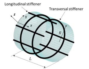
The cylindrical shell is circular, of radius (R) and length (L) and has a thickness (t) reinforced with longitudinal stiffeners or stringers and transverse stiffeners or rings. The pitch between the longitudinal and transverse stiffeners is and , respectively. An orthogonal curvilinear coordinate system is defined such that x is the longitudinal direction, y is the transverse direction following the shell contour and z is the vertical direction being positive pointing towards the shell exterior. A sketch of the shell under study is shown in Figure 1 below.
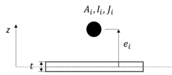
The longitudinal and transverse stiffeners are idealised as beam elements and defined by their area ( ), inertia at the centroid ( ), torsional constant ( ), and offset ( ) with respect to the shell midplane where the subscript ( ) is equal to or , if the stiffener is longitudinal or transverse, respectively. See Figure 2 below.
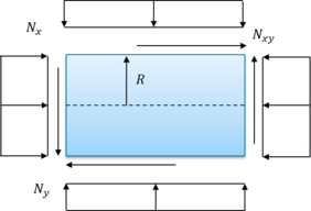
The shell is assumed to be under in-plane and/or external pressure loads. For pure external pressure loads , similarly, for uniform hydrostatic pressure, and , where is the pressure value. Figure 3 below shows the applied loads.
The shell is assumed to be simply supported or clamped at the circular loading edges.
3. Fundamental equations of shell theory
The following assumptions following Love’s first approximation [3] are considered:
- The shell is thin. That is the thickness of the shell is small when compared to other dimensions.
- Displacement, strains and rotations are small.
- Kirchhoff’s hypotheses. That is, the normals to the middle surface remain straight before and after deformation and suffer no extension. In other words, transverse shear and through thickness strains are neglected (
- The through thickness stress is small and can be neglected ( ).
- Material behaviour is linearly elastic. Materials can be metallic or composites.
The relations between the in-plane strains, curvatures and displacements are linear with z and are obtained using Donnell’s shell theory [7]. Thus,
|
|
(1) |
where, is the vector of strains, is the vector of the in-plane strains, is the vector of the curvatures, with
|
(2) |
where , and are the displacements in x, y and z directions, respectively.
The material constitutive equations of the shell are obtained by (e.g. [8]),
|
|
(3) |
where is the vector of running loads, is the vector of running moments, is the membrane stiffness matrix, is the membrane-bending coupling stiffness matrix and is the bending stiffness matrix.
The membrane, membrane-bending and bending stiffness matrix terms of the shell considering the longitudinal and transverse stiffener properties are as follows [1];
|
(4) |
where and ( or ) are the Young’s and Shear moduli for the longitudinal and transverse stiffeners, respectively. For this work, shell anisotropy is not considered.
4. Problem formulation
The Rayleigh-Ritz method is used to perform the buckling analysis of the circular cylindrical shell. This is an approximate method that uses energy principles that are equivalent to the governing differential equations (i.e., Euler-Lagrange) and natural boundary conditions [12]. The energy principle used in this work is the principle of minimum potential energy (e.g., see Ref. [8]).
In the Rayleigh-Ritz method the displacements are approximated in the form of a finite double series, such that
|
(5) |
where the functions and are the ith and jth known functions in the x and y directions, respectively that must satisfy the geometrical boundary conditions in the whole domain [13]. , and are unknown constants for the displacements in x, y and z, respectively and and are the number of terms in the series in the x and y direction, respectively. Note that denotes .
The geometrical boundary conditions considered for the shell at the circular edges (e.g., see Ref. [14]) and are shown in Table 1 below.
| Type | Geometrical boundary condition |
| S2(SS) |
|
| C1(CC) |
|
The trigonometric functions for in the x direction that satisfy the simply supported and clamped conditions (e.g., see Ref. [15]) in Table 1 are given by,
|
(6) |
The trigonometric function in the y direction is given by
|
|
(7) |
For the buckling problem, the principle of minimum potential energy takes the form,
|
|
(8) |
with
|
(9) |
where is the potential energy of the shell, is the strain energy of the shell including the longitudinal and transverse stiffeners, is work of external forces and is the critical buckling load factor.
The expression of the potential energy of the shell is found by substituting Equations (1)-(4) in Equation (9) and rearranging,
|
(10) |
The solution of the problem is found by substituting Equation (5) in Equation (10) and minimising with respect to each of the displacements’ unknown coefficients. Hence,
|
(11) |
This generates a system of linear equations with unknowns. Thus,
|
|
(12) |
where , and are the unknown coefficients of the displacement vectors, each of dimension, are squared matrices each of dimensions related to the shell’s stiffnesses and is a squared matrix of dimensions, related to the applied loads. This linear system is homogeneous and can be solved as an eigenvalue problem. The first eigenvalue will provide the critical buckling load such that,
|
|
(13) |
5. Numerical results
The semi-analytical method presented in this paper was developed in Fortran [16]. Integrals to obtain the matrices in Equation (12) were computed numerically. Results from the semi-analytical approach were compared against analytical solutions and detailed finite element models reported in the literature. Sensitivity studies were performed to determine the number of terms in the x and y directions in the series that guarantee accurate predictions for the eigenvalue obtained with Equation (12). Even for a large number of terms in the series the method was very fast providing result within seconds. Unstiffened and stiffened circular cylindrical shells made of metallic or composite materials subjected to different states of loading were considered.
First, results and comparisons are presented for unstiffened shells. ]]Table 2 shows the non-dimensional buckling pressure for isotropic unstiffened circular cylinders with simply supported edges and subjected to uniform external pressure for several Batdorf parameters . The shell is made of a metallic material with (Poisson’s ratio). From Table 2, it can clearly be seen that the present method provides identical and nearly identical results to those reported in [1] and [17], respectively. The maximum difference is approximately 0.6% for .
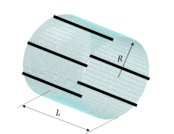
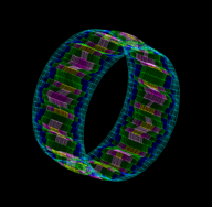
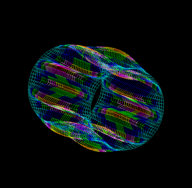
It can also be seen that, the number of longitudinal half-waves and circumferential waves obtained with the present method coincided with those reported in [1]. Figure 4 displays two examples of the buckling modes obtained with the present method that are reported in Table 2.
|
|
Next, Table 3 below provides the buckling pressure for isotropic unstiffened circular cylinders with simply supported edges and subjected to external pressure. The shell is made of a metallic material with and . Results are provided using 10x20 and 10x30 terms in the trigonometric series for and , respectively. From Table 3 , it is clearly seen that the present method provides identical results to those reported in [1] and compares well with the detailed finite element models reported in [18]. The maximum difference in this case is approximately 5.2% for and .
Shells with different boundary conditions were also considered. Table 4 below provides the buckling pressure for isotropic unstiffened circular cylinders with clamped edges and subjected to external pressure. As before, the shell is made of a metallic material with and . Results are provided using 35x20 and 35x35 terms in the trigonometric series for and , respectively. The results in Table 4 indicate that the present method compares well with the detailed finite element models considering clamped edges reported in [18]. The maximum difference observed is approximately 4.7% for and .
| Unstiffened shell | Ref. [18]
FEM |
Present | ||

|
300 | 0.5 | 3462 | 3624 |
| 1 | 1703 | 1731 | ||
| 2 | 878.4 | 880.1 | ||
| 3 | 585.5 | 583.6 | ||
| 5 | 358.4 | 352.6 | ||
| 3000 | 0.5 | 10.80 | 10.96 | |
| 1 | 5.516 | 5.529 | ||
| 2 | 2.799 | 2.791 | ||
| 3 | 1.874 | 1.865 | ||
| 5 | 1.128 | 1.120 |
In addition, shells made of composite materials were also studied. Table 5 below provides non-dimensional buckling loads for unsymmetric cross-ply circular cylinders with simply supported edges and subjected to axial compression. The radius and thickness of the shell are 10 and 0.01 inches respectively. Ply properties used are , , and . Results are provided using 10x10 terms in the trigonometric series. From Table 5, it can be observed that the present method provides results that are slightly stiffer than those reported in [19]. The maximum difference in this case is approximately 8.6% for the (0/90) lay-up with .
Secondly, results for shells stiffened with longitudinal stiffeners or stringers are presented. Table 6 gives the non-dimensional buckling coefficient for isotropic circular cylinders with eccentric stringers with simply supported edges and subjected to axial. The shell is made of a metallic material with . Results are provided using 10x10 terms in the trigonometric series. Table 6 shows the present method provides identical results to those reported in [1] and in [20] (as cited in [1]).
Finally, results for shells stiffened with transverse stiffeners or rings are presented. Table 7 provides the non-dimensional buckling pressure for isotropic circular cylinders stiffened with eccentric rings with simply supported edges and subjected to uniform external pressure. The shell is made of a metallic material with . Results are provided using 10x10 terms in the trigonometric series. From Table 7, it can clearly be seen that the present method provides results that are identical to those reported in [1] and nearly identical to those in [21-22] (as cited in [1]).
6. Concluding remarks
A semi-analytical approach using the Rayleigh-Ritz method was developed to calculate the linear buckling onset of metallic and composite circular cylindrical shells with various boundary conditions and subjected to in-plane and/or pressure loads. Donnell’s [7] shell theory was used due to its simplicity. Results for unstiffened and stiffened shells were compared with analytical solutions and detailed finite elements reported in the literature. Overall, the present method provided accurate results. For the metallic shells considered the present method provided results identical to the analytical results reported in [1] and close to the detailed finite element models results found in [18]. The maximum differences with detailed finite elements were 5.2%. For the composite shells considered, the present method provided slightly stiffer results than the analytical ones reported in [19]. For this case, the maximum differences were 8.6%. The present method was computationally fast even when large number of terms were used in the trigonometric series. Both its accuracy and computational speed makes the present method an ideal candidate to be used as part of an optimization scheme and/or to reduce potentially the number of detailed finite element models employed in the early design phases.
References
| [1] | M. P. Nemeth, Buckling analysis for stiffened anisotropic circular cylinders based on Sander's Non-linear shell theory, NASA/TM-2014- 218176. | |
| [2] | M. P. Nemeth, A Leonard-Sanders-Budiansky-Koiter-Type Nonlinear Shell Theory with a Hierarchy of Transverse-Shearing Deformations, NASA/TM-2014- 218176. | |
| [3] | A. E. H. Love, A treatise on the mathematical theory of elasticity, 1st edition, Cambridge Univ. Press, 1892. | |
| [4] | S. A. Timoshenko, Theory of plates and shells, Mc-Graw-Hill, New York, 1959 | |
| [5] | W. Flügge, Stresses in shells, Spring-Verlag, Berlin, 1962. | |
| [6] | V. Z. Vlasov, General theory of shells and its applications in engineering (English translations) NASA TT F-90. | |
| [7] | L. H. Donnell, Stability of thin walled tubes under torsion. NACA Rept. No. 479, 1943 | |
| [8] | J. E. Ashton and J. M. Whitney, Theory of laminated plates, 1970 | |
| [9] | S. A. Timoshenko. and J. M. Gere, Theory of Elastic Stability, 2nd edition, McGraw Hill Book Company, 1961. | |
| [10] | R. Vescovini, L. Dozio, M. D’Ottavio and O. Polit, On the application of the Ritz method to free vibration and buckling analysis of highly anisotropic plates. Composite Structures, 192, 460-474. 2018, https://doi.org/10.1016/j.compstruct.2018.03.017 | |
| [11] | L. Meirovitch and M. K. Kwak, M. K., Convergence of the classical Rayleigh-Ritz method and the finite element method, AIAA Journal, 28(8), 1509–1516, 1990. https://doi.org/10.2514/3.25246 | |
| [12] | J. N. Reddy, Energy Principles and Variational Methods in Applied Mechanics (2nd ed.). Wiley, 2002. | |
| [13] | D. V. Wallerstein, A Variational Approach to Structural Analysis. Wiley, 2002. | |
| [14] | B. O. Almroth, Influence of Edge Conditions on the Stability of Axially Compressed Cylindrical Shells, AIAA Journal, Vol. 4, No. 1, 1965. | |
| [15] | H. Fukunaga, H. Sekine, M. Sato, and A. Iino, Buckling design of symmetrically laminated plates using lamination parameters. Computers & Structures, 57(4), 643–649, 1992 | |
| [16] | W. H. Press, S. A. Teukolsky., W. T. Vetterling, B. P. Flannery and M. Metcalf, Numerical Recipes in Fortran 90: Volume 2, Volume 2 of Fortran Numerical Recipes: The Art of Parallel Scientific Computing (2nd ed.). Cambridge Univ. Press, 1996. | |
| [17] | N. Yamaki, Buckling of circular cylindrical shells under external pressure, Reports of the institute of high speed mechanics, Vol. 20, No. 196,1968-1969 . | |
| [18] | H. Showkati and P. Ansourian, Influence of primary boundary conditions on the buckling of shallow cylindrical shells, Journal of constructional steel research, Vol. 36, No. 1, 1996. | |
| [19] | R. M. Jones and H. S. Morgan, Buckling and vibration of cross-ply laminated circular cylindrical shells, AIAA Journal, Vol. 3, No. 5,.1995. | |
| [20] | J. Singer, J. Arbocz and C. D. Babcock, Buckling of imperfect stiffened cylindrical shells under axial compression, AIAA Journal, Vol. 9, No. 1,.1971. | |
| [21] | J. Singer, M. Baruch and O. Hariri, Inversion of the eccentricity effect in stiffened cylindrical shells buckling under external pressure, Journal of Mechanical Engineering Science, Vol. 8, No. 4, 1966. | |
| [22] | J. Singer, M. Baruch and O. Hariri, Further remarks on the effect of eccentricity of stiffeners on the general instability of stiffened cylindrical shells, TAE Report No. 42, Technion research and development foundation, 1965. |
Document information
Accepted on 05/12/23
Submitted on 31/05/23
Licence: Other
