1. Introducción
The aeronautical sector has increased the carbon fibre (CF) demand in the last years, and it is expected a continuous growing in the near future due to a higher demand of composite materials for the manufacturing of aircraft, that also occurs in other sectors [1]. The use of CF composites provides suitable components according to weight and design flexibility but faces some challenges in the area of manufacturing and assembly with the need of special processes, hand operations and large lead time.
The use of CF composites in the past, and the expected growth, has converted the recycling and reuse of the CF composites, especially those using thermosets, in an urgent need to minimize the environmental impact and to advance towards an efficient use of resources. There are two main goals to recycling composite materials waste: the first is to avoid placing waste in landfills, and the second, and perhaps more important, is to find ways to recover and reuse these materials in useful (and profitable) applications [2]. This trend results in several approaches like the development of near net shape production processes, use of thermoplastic matrix, scrap recycling by thermal and thermochemical processes and scrap reuse of uncured prepreg [3].
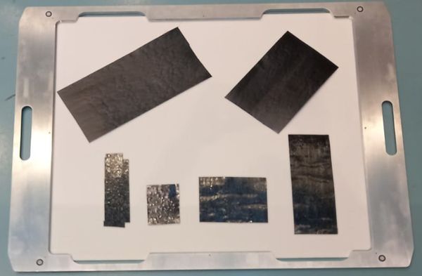
The manufacturing processes of composites components in the aeronautical sector result in a buy to fly ratio around 1.1 – 1.4, involving around a waste of material up to 30% in the form of scrap [4]. A significant part of this waste material is the result of the automation of the manufacturing using processes like Automated Tape Laying (ATL) and Automated Fibre Placement (AFP), but also from manual laying processes. These generate significant amounts of uncured scrap in the form of leftovers, cut-outs, end of rolls or out of date rolls.
The reuse of non-cured scraps is interesting in order to minimize the residue and to valorise it. It is more suitable than that of the cured material to obtain recycled carbon fibres (rCF) because of the lower associated cost to reuse the material and the use of a material slightly degraded compared to the virgin material, despite not being acceptable for its use in primary and critical structures.
The intermediate product that can be obtained from prepreg scraps can come in several formats, like prepreg rolls, regular cut-outs or loose chips [3]. The value and applicability of the material is higher as long as they maintain the original form. Additionally, the reuse of this kind of materials in high volume involves handling issues depending on the format according to the manufacturing step in which they are obtained [5], including low temperature maintenance, suitable storage for avoid further damage, etc.
One of the technologies for the reuse of uncured prepreg scrap is the generation of chips and the subsequent use for compression moulding processes with randomly oriented fibres. The production of sheets formed by chips for manual lamination process is also possible [1].
The reuse of the prepreg scraps and the obtaining of chips, normally rectangular, with predefined dimensions is performed by a cutting process. The automation of this process is needed to increase the productivity and the amount of material recovered, providing the chips in a suitable way for subsequent processes. Different cutting processes [1] [6] have been studied to produce regular chips, arising some problems associated to the tack of the material; while the resulting subproduct is an unordered pile of chips or a randomly distributed sheet without density control.
This work summarizes the work carried out within the RECYCOMP project focused on the reuse of uncured unidirectional CF prepreg scrap material coming from lamination process. The process is performed avoiding the degradation and preparing the material in a suitable form for the generation of new pre-impregnated material useful for the lamination process of new components. The equipment developed is explained and the expected processing times are analysed.
2. Process definition
The recycling process to achieve the reuse of the uncured scrap material follows different stages to prepare the material. The main steps are identified in the following figure.
The process is feed using trays where the material to be recycled is placed, passing these trays through the different modules and processes indicated above. The input tray has a useful area of 550x700 mm. The management of the trays and their movement between the different modules is performed using a conveyor.
The input material is cut in chips with dimensions of 50x8 mm and the recycled material is formed by multiple chips ordered uniformly over a backing paper in a sheet of 500x1000 mm to obtain a controlled density and behaviour of the output material. So, the result of the process is a sheet with several layers of chips with different and controlled orientations, and several input trays are needed to obtain the output product as a sheet formed by multiple chips ordered.
The sequence of operations is summarized as:
- Manual resize of the leftovers in suitable size for the tray.
- Place the leftovers in the tray without folds or wrinkles, as flat as possible.
- Load of the tray in the equipment.
- Identification of the scrap shape and orientation of the fibres using computer vision.
- Definition of the pattern and process path to cut the prepreg chips
- Cut the material to obtain prepreg chips using a cutter in the cutting head
- Pick-placing process to distribute the prepreg chips in the output support material using a robotic manipulation system with specific grippers.
The system is prepared for unidirectional CF prepreg in the form of single layer prepreg plies with irregular shapes without the backing paper or film.
In order to ensure the repeatability of the process, it is performed in a controlled environment room with 22 ± 3 °C and 30 to 65 percent RH. In this way, the state of the material is controlled during the processing and suitable conditions are obtained for the cutting and handling operations, especially a repetitive tack of the material.
3. Developed solution
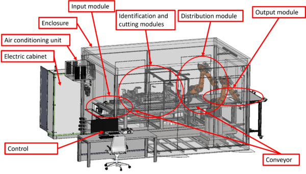
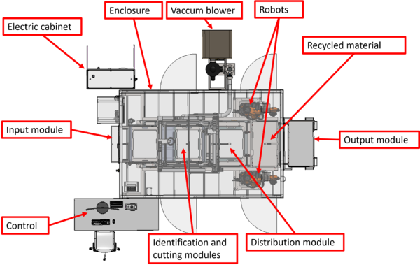
The overall concept for the recycling equipment is based on an integrated machine able to detect the characteristics of the scrap material, and from that information perform the cutting and distribution processes to obtain a new raw ordered material ready for lamination processes. The general concept can be seen in the next figure, and the overall size of the equipment is 4 x 5.5 meters with a height 3.2 meters.
The main modules included are:
- Loading module: To feed the prepreg scraps into the machine with the tray support
- Identification module: Computer vision for identification of the scraps size and fibre orientation.
- Cutting module: To cut the scraps in chips with suitable and equal dimensions.
- Distribution module: to place the chips ordered in the backing support of the output module.
- Output module: to extract the backing support with the recycled material sheet once completed.
- Enclosure for safety reasons and to achieve the required environmental conditions.
The different modules are complemented with different key elements that are added to the main modules with significant importance in the machine development and the process performance. These are:
- Tray as the main processing unit for the prepreg scraps, with a surface made of porous polymer.
- The conveyor manages the movement of the trays between the modules.
- Vacuum system to fix the prepreg to the tray during cutting, avoiding undesired movements.
- Air conditioning equipment to maintain the environmental conditions.
- Fix devices for the trays at the different positions.
- Cameras to identify the positioning of the tray within the workspace of each module, detecting the marks included in the tray to assess its positioning.
- Safety devices.
3.1. Identification module
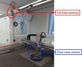
The identification module obtains information about the geometry of the leftovers, their positions relative to a known reference (tray) and the orientation of the main fibre direction in each leftover. The solution is based on the use of a computer vision system composed of two cameras:
- Full field camera. This is a camera located over the tray, allowing the identification of the tray reference marks to allow the positioning of the tray in the working space. This camera also allows the identification of the prepreg leftovers and their borders.
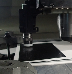
- Close view camera. This is a camera that is moved to the centre of each leftover located in the tray to identify the fibre orientation. This camera is moved by 2D CNC axes, and it works with special darkfield illumination that allows the suitable identification of the fibre orientation in each leftover.
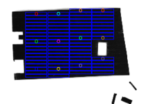
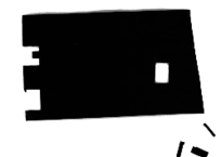
The position of these two kinds of cameras within the identification module can be seen in Figure 4. The figure shows the identification of the leftover and the subsequent chips definition within the leftover according to the fibre orientation.
|
|
The use of full field cameras is also available in the distribution and the output modules to control the position of the tray and to perform the management of the chips in both modules.
3.2. Cutting module
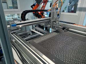
The cutting module shares space with the identification module in a dual gantry CNC module. In the first crossbeam the close view camera of the identification module is mounted; while in the second, the cutting head is installed. So, this CNC module has two functions that do not operate simultaneously.
The cutting module has four degrees of freedom: 3 linear axes for locating the cutter, and 1 rotation axis to orient the cutter with the fibre direction or normal to it.
In order to prevent undesired movement of the tray due to cutting forces, four clamping units fix the tray in place. Below the belt of the conveyor, a suction system is installed, providing a fixing force through the tray porous polymer material to maintain the leftover in place during the cutting operation.
The process is performed according to straight movements to obtain the chips’ matrix shown in Figure 4
3.3. Distribution module
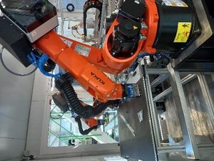
The distribution module deals with the pick and place operations of the chips. The robots pick groups of chips with a special gripper, and they place them in the support material of the output module to generate the recycled material following an ordered sequence of chips.
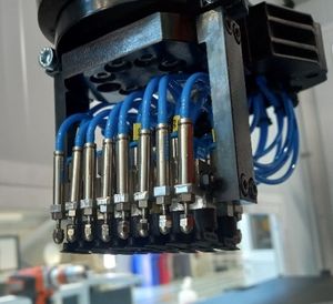
The system for the pick-placing process of the chips consists of two robots mounted with a specific gripper able to pick the chips using vacuum pads and place them using linear pneumatic actuators. The gripper can pick up to 8 chips in the same operation and the pneumatic actuation for each chip is controlled independently. The system is show in the next figure.
The system performs the pick and place operation according to the known positions of each chip within the input tray. The two robots work coordinated in the input and output areas to increase the productivity, avoiding collisions.
4. Conclusions
The chips are placed over a support film to generate a prepreg sheet formed by ordered chips. This order is defined by a pattern of several layers, ensuring a repetitive behaviour and a homogeneous material according to the fibre orientation and areal weight.
The main requirements for the structure of the recycled material are to obtain controlled density and behaviour. So, the patterns are defined to provide directional control of the fibers in order to control the strength and stiffness of the material.
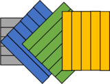
Two different approaches are identified for the recycled material lay-out:
- Unidirectional plies with at least two layers that will be later laid up in different orientations to obtain the desired properties in the manufactured multilayer components.
- Multidirectional plies with 4 layers that will be later laid up in the manufactured multilayer components to obtain a quasi-isotropic behaviour.

|
|
| Unidirectional plies (0) | Multidirectional plies (0,45,-45,90) |
Summarizing, quasi-isotropic behaviour in the components can be achieved from unidirectional plies later ordered during lay-up, or multidirectional plies without a strict order during lay-up.
The expected productivity of the recycling equipment is between 2.5 and 4.5 kg/h, with a controlled environment and a short processing time to maintain the shelf life of the recycled material.
References
| [1] | C. Chadwick, K. Kalaitzidou y J. Colton, «Processing of post-industrial unidirectional prepreg tapes using SMC equipment,» The International Journal of Advanced Manufacturing Technology, nº 121, pp. 2831-3839, 2022. |
| [2] | D. Brosius, «Composites recycling — no more excuses,» 21 02 2023. [En línea]. Available: https://www.compositesworld.com/articles/composites-recycling-no-more-excuses. [Último acceso: 18 05 2023]. |
| [3] | G. Nilakantan y S. Nutt, «Reuse and upcycling of thermoset prepreg scrap: Case study with out-of-autoclave carbon fiber/epoxy prepreg,» Journal of Composite Materials, vol. 52, nº 3, pp. 341-360, 2018. |
| [4] | T. Blanco, N. Colas, J. Sánchez, A. Ricardo y N. Fanegas, «Reuse of aeronautical uncured prepreg,» de MATCOMP, 2018. |
| [5] | J. Cárdenas y G. Galera, «Reuse of CFRP material from Aircraft Manufacturing Parts. Industrial applications and inverse logistic solution.,» de MATCOMP, 2018. |
| [6] | G. Nilakantan, R. Olliges, R. Su y S. Nutt, «REUSE STRATEGIES FOR CARBON FIBER-EPOXY PREPREG SCRAP,» de CAMX Conference Proceedings, Orlando, 2014. |
Document information
Published on 15/10/23
Accepted on 28/08/23
Submitted on 22/05/23
Volume 08 - COMUNICACIONES MATCOMP21 (2022) Y MATCOMP23 (2023), Issue Núm. 2 - Fabricación y Aplicaciones Industriales - Sostenibilidad y Reciclaje., 2023
DOI: 10.23967/r.matcomp.2024.02.14
Licence: Other
Share this document
Keywords
claim authorship
Are you one of the authors of this document?

