Abstract: Structural assessment is a main concern when designing and operating any sort of offshore structure. This assessment is meant to ensure that the structural integrity is preserved along the lifespan of the asset, withstanding the worst sea-states that will be encountered and making sure that the accumulated fatigue damage will not jeopardize its structural integrity neither. The purpose of this paper is to present a fast and reliable hydroelastic model. This model is based on time-domain tight-coupling of a three-dimensional FEM (finite element method) linear structural model and a three-dimensional FEM seakeeping hydrodynamics model. In order to reduce the computational cost of structural dynamic simulations, the high-fidelity structural solution is projected onto the modal basis to obtain the modal matrix system and to extend the response amplitude operators (RAO) to the modal responses (MRAO). From there, the number of structural degrees of freedom can be greatly reduced by retaining only those eigenmodes preserving most of the structural elastic energy. The use MRAOs and/or the large reduction in structural degrees of freedom allows us to: first, quickly analyse the large number of loadcases required on the design stage; and second, to implement a digital twin for structural health monitoring in operational conditions. The paper also presents an application case of the developed methodology.
Keywords: hydroelasticity; seakeeping; offshore engineering; modal matrix reduction; coupled fluid-structure interaction
1. Introduction
Hydroelasticity is a hot topic in naval architecture and marine and offshore engineering. The numerical analysis of the hydro-elastic response of a ship or offshore platform requires the coupling between the seakeeping hydrodynamics and the structural dynamics.
Looking at the literature, the most common approach is to model seakeeping hydrodynamics, solving the wave diffraction-radiation problem using a three-dimensional boundary element method (BEM) in the frequency domain and modelling the structural problem using a one-dimensional beam model solved by the finite element method (FEM) [1–6]. Several works have extended the seakeeping hydrodynamic model solving the Navier-Stokes equation instead of using potential flow [7–9]. The Navier-Stokes solvers, despite being quite a bit more expensive computationally speaking, are recommended for those fluid structure interaction problems where potential flow solver cannot properly capture the physics of the problem under analysis. This is the case of severe wave conditions with high non-linear effects, such as slamming and green waters. In this regard, some of the most recent works are [10,11], where a two-way coupling is developed and applied to the S175 containership under severe wave conditions to analyse the before-mentioned effects.
From the structural point of view, only a few authors have moved to more sophisticated FEM models, such as the one-dimensional–three-dimensional FEM [3,6], quasi-static approximations, or direct coupling with a three-dimensional FEM model [12]. Most of these works only look at the linear response, and the most common approach for the structural dynamics is the modal superposition considering a very limited number of modes [12–14]. However, in order to be able to simulate transient and/or non-linear responses, it is necessary to directly solve in the time-domain condition [13].
To simulate transient or non-linear responses, Cummins [15] proposed an impulse response function to transfer frequency domain results into the time-domain, and different authors have followed this approach [1,2,6,16]. This method requires, first, to carry out the modal analysis, and, second, to solve the radiation problem for each displacement mode. In case a large number of modes are to be considered, the computational effort greatly increases. A shortcoming of this approach is that it is not capable of capturing local stresses, which is mandatory to predict structural failure [17]. To overcome this shortcoming, it is necessary to solve the three-dimensional fully coupled hydroelastic problem in the time-domain. However, this approach is quite rare in the literature due to its complexity and high computational cost. In [18], the present authors implemented a partitioned strategy to analyse the interaction of the free surface with the seals of a surface affect ship. The hydrodynamic model was based on potential flow with forward speed, and the results were validated against experimental tests. In [5], the hydroelastic response of a S175 ship using BEM–FEM coupling was compared, the results against the equivalent rigid body solution were presented.
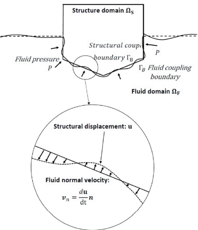
One of the most recent works in hydroelasticity using potential flow for seakeeping hydrodynamics was published by the present authors in [19]. In that work, a tightly coupled hydroelastic model was developed within SeaFEM (a time–domain wave diffraction-radiation solver based on FEM [20–22]). A comparison between iterative and monolithic coupling is carried out, as well as a comparison between loose (weak, one-way) and tight (strong, two-way) coupling. It was concluded that monolithic coupling is the most robust (from the numerical stability). In any case, the computational cost is still too high and is mostly taken by the structural dynamics solver. The governing equations of the hydroelastic problem are those of the wave diffraction-radiation problem in the time domain, along with the linear structural equations solved with FEM [19]. The coupling is carried out at the wet surface of the floater, where the seakeeping hydrodynamics solver (SeaFEM) sends pressure values to the structural solver, and the latter sends back the structural displacements on the same surface. The time variation of the structural displacements along the surface normal direction are imposed as a normal velocity boundary condition on the wet surface (see Figure 1).
Figure 1. Hydroelastic coupling on the body wet surface.
Mahérault et al. [23] proposed, also, to use the modal approximation for calculating the fatigue damage of ULCS due to springing. The hydroelastic model is based on a three-dimensional structural BEM and a three-dimensional seakeeping BEM. In that work, the total structural solution is separated into a quasi-static solution, accounting for the hydrodynamic pressure under rigid body motion, and a dynamic solution, accounting for low frequency modes. This separation was used to avoid a solution convergence problem when using the modal basis. However, limiting the modal solution to the lower frequency modes is only valid when the elastic energy is mostly concentrated in those modes, which is not the general case.
The present work can be seen as an evolution of [19] to reduce the computational time of the structural solver (which is the dominant one). This reduction is achieved by projecting the high-fidelity structural solution onto the modal basis to obtain the modal matrix system. The structural model is also tightly coupled with the time–domain wave diffraction-radiation solver SeaFEM. Since SeaFEM is based on the FEM, the mesh used for the wet body boundary condition might have the same or similar discretization to the structural mesh to ensure no loss of accuracy for local modes. In those cases where the local modes are not excited, different mesh discretization can be used with no interpolation issues, as reported in [19]. As shown in the application example of this work, no modal converges issues have been detected when using the approximation presented in this work.
2. Structural Model Order Reduction
In [26], it was concluded that the three-dimensional fully coupled hydroelastic problem in the time–domain is very expensive computationally speaking, and most of the computational work is taken by the structural solver. Hence, in this work, a modal order reduction is proposed for the structural problem, aiming at reducing the computational cost of fully coupled simulations.
The main idea underlying this work is to accurately approximate the high-fidelity FEM solution to the structural problem by projecting the FEM solution onto a subspace of solutions with a dimension number (number of degrees of freedom), which is several order of magnitudes smaller than the FEM solution. The subspace of solution is built using the modal matrix reduction (MMR) technique, where the projection subspace is built with the basis of vectors obtained from modal analysis.
The high-fidelity FEM solution can be expressed as:
|
|
(1) |
where , is the nodal displacements vector of the structure, are the vectors of the modal basis, and temporal variations of the modal amplitudes. The modal basis is obtained from the eigenvalue problem:
|
|
(2) |
where and are the structural mass and stiffness matrices obtained via FEM. Additionally, the eigenvalue problem is:
|
|
(3) |
where; is the eigenvalue of matrix associated to eigenvector , and is the modal frequency. For the modal basis, the following relations hold:
|
|
(4) | |
|
|
(5) |
Form this point on, it is assumed that eigenvectors are normalized with respect to ( ). In the general case, the governing equation of structural dynamics is:
|
|
(6) |
where; is a damping matrix, and is the external loads vector. Introducing Equation (1) into Equation (6), the following holds:
|
|
(7) |
where; and . Multiplying Equation (7) by , the diagonal modal matrix system is obtained:
|
|
(8) |
where; is the modal damping, and . For the sake of simplicity, the modal damping will be modelled as a fraction of the critical damping, . Then, we obtain:
|
|
(9) |
Equation (9) is a second-order ordinary differential equation, representing the dynamics of each structural mode. In the context of this work, this equation will be solved numerically using the same scheme used by SeaFEM for the rigid body motion. This is a Newmark scheme with coefficients and [22].
The modal elastic energy will be used to identify those modes most excited. The modal elastic energy is given by:
|
|
(10) |
3. Hydroelastic Model
The hydroelastic model proposed in this work consists of coupling a time-domain wave diffraction-radiation solver with a time-domain structural solver, as was previously performed by the authors in [26]. The main difference in this work is that, instead of using the full FEM structural solver, the reduced structural model based on MMR will be used.
Using this approach, the number of degrees of freedom can be reduced by several order of magnitudes while still having an accurate structural solution. This is achieved by considering only modes excited by the external loads. Doing so, the computational time of the structural problem (and the hydroelastic problem) can be greatly decreased, so that dynamic hydroelastic simulations in the time–domain can be affordable from a computational point of view.
If the hydroelastic problem is assumed to be linear (linear structural model and linear external loads), it is possible to compute modal response amplitude operators (MRAOs), as is usually performed for the six rigid body drees of freedom. Obtaining the MRAOs allows one to pre-calculate the structural response offline, and then we use them to obtain the structural response under specific scenarios with no need of solving the hydroelastic problem again (see Figure 2). The linearization of the problem obtaining MRAOs can be also used to identify those modes that will be most excited under specific scenarios, and only those were used to compute the structural response.
Figure 2. Computing the modal response to a specific sea-state given the MRAOs.
This can be used in operative conditions where there is little time for computation and, also, to estimate long term response. For instance, this approach facilitates the calculation of the accumulated fatigue damage throughout the lifespan of the structure given the environmental scenarios the structure will encounter and their probability.
The aforementioned approach requires carrying out a modal analysis of the structure. In order to use the MRAOs offline, a number of hydroelastic analysis must be carried out to precompute the MRAOs under different wave directions and frequencies. This offline extra effort will be compensated for with the ease for estimating long term responses and, also, if the number of load cases to be analysed is large enough.
4. Application Example
4.1. Buoy Model Definition
For the sake of simplicity, in order to demonstrate and understand the present hydroelastic approach, it is applied to a floating buoy made of steel. This results in a simple structure with a not too large number of degrees of freedom, where it is cheaper to compute the structural modes. Then, analysis of such an energy distribution across structural modes is easier to show and understand.
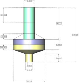
The described hydroelastic model is applied to a floating buoy model to verify the accuracy of the hydroelastic model with reduced structural model using MMR. Figure 3 shows the buoy’s main dimensions. The structure of the buoy is stiff.
Figure 3. Buoy main dimensions.
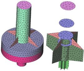
The buoy is made of steel plates. It is moored, and the fairlead point is located at the intersection of the vertical centre line and the lowest surface. Decay tests have been carried out using SeaFEM to find out the natural periods. Viscous damping for surge, sway, roll, and pitch have been estimated as 5% of the critical ones. The buoy and mooring particulars are given in Table 1. Table 2 provides the particulars of the structural FEM model, and Figure 4 shows the FEM mesh used for the structural part.
Table 1. Buoy and mooring particulars.
| Buoy Displacement | 1005 kg |
| Material | Steel |
| Steel density | 7844 kg/m3 |
| Steel Young modulus | 2.1 GPa |
| Steel Poisson coefficient | 0.3 |
| Plate thickness | 5 mm |
| Mass | 669 kg |
| XG | 0 m |
| YG | 0 m |
| ZG | 1.1933 m |
| Radii of gyration XX | 0.8061 m |
| Radii of gyration YY | 0.8061 m |
| Radii of gyration ZZ | 0.563 m |
| Displacement | 1005 kg |
| Mooring vertical force | −3300 N |
| Mooring horizontal and vertical stiffness | 2000 N/m |
| Surge/Sway natural period | 4.94 s |
| Heave natural period | 1.5 s |
| Roll/Pitch natural period | 2.55 s |
| Surge/Sway viscous damping | 5% critical |
| Roll/Pitch viscous damping | 5% critical |
Table 2. Structural FEM particulars.
| Number of Nodes | 2077 |
| Number of triangular elements | 4628 |
| Number of degrees of freedom | 12,462 |
| Type of shell element | Drilling rotations (3 + 3) |
Figure 4. Buoy FEM mesh.
4.2. Modal Analysis
The first step to implement the MMR technique is to carry out the modal analysis of the corresponding structure. For the buoy with no restrictions, the total number of elastic modes is equal to the number of degrees of freedom minus the six rigid body degrees of freedom. In order to solve the eigenvalue problem, the Intel MKL library has been used. It allowed us to compute 11,311 elastic modes, which represent over 90% of the total elastic modes. The corresponding modal frequencies range from 85.97 Hz to over 34.14 MHz.
4.3. Equilibrium Load Case
As a first load case, the buoy is considered to be in equilibrium, subject to the self-weight load, hydrostatic pressure load, and the mooring vertical force. This loadcase is computed using the classic FEM computation and using the MMR technique.
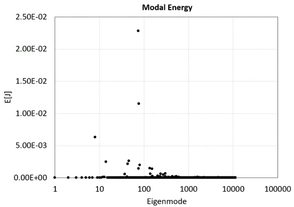
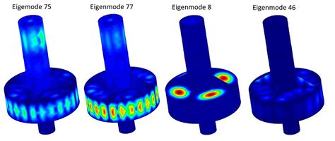
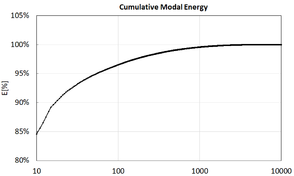
Figure 5 shows how elastic energy is distributed across modes. Table 3 provides the values of the most energetic modes. Figure 6 shows the displacements field of the most energetic modes. Figure 7 shows the cumulative energy after ordering the modes from most to least energetic. Only Eigenmode 75 contains over 35% of the total elastic energy, the 17 most energetic eigenmodes retain over 90%, only 54 modes are necessary to retain 95% of the elastic energy, and 474 are necessary to retain 99%.
Figure 5. Modal energy distribution.
Table 3. Energy distribution and cumulative energies from the most energetic modes.
| Eigenmode | E [J] | E (%) | Cumulative E | |
| 1 | 75 | 0.0228332 | 35.64% | 35.64% |
| 2 | 77 | 0.0114983 | 17.95% | 53.59% |
| 3 | 8 | 0.0063053 | 9.84% | 63.44% |
| 4 | 46 | 0.002605 | 4.07% | 67.50% |
| 5 | 14 | 0.00248766 | 3.88% | 71.39% |
| 6 | 43 | 0.00214753 | 3.35% | 74.74% |
| 7 | 80 | 0.00197565 | 3.08% | 77.82% |
| 8 | 134 | 0.00146029 | 2.28% | 80.10% |
| 9 | 76 | 0.00143945 | 2.25% | 82.35% |
| 10 | 153 | 0.0014098 | 2.20% | 84.55% |
| 11 | 303 | 0.00066381 | 1.04% | 85.59% |
| 12 | 139 | 0.00062466 | 0.98% | 86.56% |
| 13 | 237 | 0.00061825 | 0.97% | 87.53% |
| 14 | 37 | 0.00058216 | 0.91% | 88.44% |
| 15 | 271 | 0.00048755 | 0.76% | 89.20% |
| 16 | 203 | 0.00027932 | 0.44% | 89.63% |
| 17 | 155 | 0.00025525 | 0.40% | 90.03% |
Figure 6. Most energetic eigenmodes: displacement contour fill.
Figure 7. Cumulative modal energy.
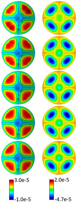
Figure 8 compares the vertical displacement field using the MMR approximation for different sizes of the modal basis, as well as the direct FEM solution. It is observed how even using only 17 modes (retaining 90% of the elastic energy), the displacement field is quite close to the one obtained by the FEM solution. As the size of the modal basis increases, the solution is better approximated. A modal basis, retaining 99% of energy, allows a reduction in the number of degrees of freedom of the system from 12,462 to 474, which means a 96.2% reduction.
Figure 8. Bottom view (left) and top view (right) of vertical displacement field obtained for static case. From top to bottom: MMR with 17 modes; MMR with 54 modes; MMR with 474 modes; MMR with all modes; FEM solution.
4.4. Dynamic Load Case: Irregular Waves Response
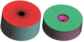
Next, the hydroelastic response of the buoy under the actions of dynamic loads due to waves is presented. The hydroelastic response is obtained using a strong (tight) coupling between the seakeeping hydrodynamics and the structural dynamics. Then, the hydrodynamics pressure over the wet surface of the buoy is sent to the MMR model, and the MMR is sent back the structural displacements to be imposed on the wet surface. Hence, added mass and damping due to wave radiation, as well as increase in stiffness due to hydrostatic pressure, are taken into account. An iterative scheme ensures the convergence of both, hydrodynamic pressure and structural displacements, before moving to the next time step. The time stepping and iterative schemes used in the partitioned scheme are the ones used in [19], but this is accomplished just by using the MMR solver instead of the FEM solver. Table 4 provides the particular of the SeaFEM model and the scenario to be calculated, and Figure 9 shows the computational domain used.
Table 4. SeaFEM model particulars.
| Computational Domain Radius | 25 m |
| Computational domain depth | 25 m |
| Number of tetrahedrons | 147,101 |
| Time step | 0.097 s |
| Initialization time | 50 s |
| Simulation time | 200 s |
| Wave Spectrum | Jonswap |
| Mean wave period | 2.5 s |
| Wave height | 1 m |
| Wave Energy ( ) | 628.2 J |
| Wave direction | 0º (OX axis) |
Figure 9. SeaFEM whole (left) and inner (right) computational domains.
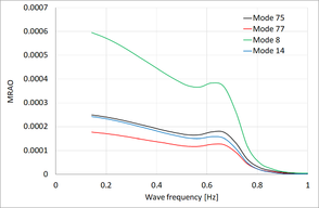
First, the hydroelastic response of the buoy under monochromatic waves (MRAOs) is obtained. For this purpose, a white noise spectrum with wave periods between 0.143 Hz and 1 Hz is used. Figure 10 shows the MRAOs obtained for some relevant eigenmodes. It is observed that a local maximum happens for the heave natural frequency. The modal response for a specific wave scenario is automatically obtained by multiplying the MRAOs and the wave amplitudes. Then, for a specific eigenmode m, a realization for the modal amplitude is quickly obtained by:
|
|
(11) |
where; si the modal amplitude obtained for the static equilibrium case, and are the amplitude and frequency of the wave, is the modal phase delay respect to the wave, and is a random phase to generate a realization of an irregular sea-wave spectrum.
Figure 10. MRAOs for most relevant eigenmodes.
The average modal energy during a long realization can be obtained as:
|
|
(12) |
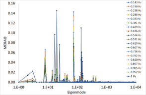
where; is the static contribution of the equilibrium state, and is the dynamic contribution. For the dynamic contribution, we can define the Modal Energy Response Amplitude Operator (MERAO) as:
|
|
(13) |
which is an indicator of how much structural energy is induced by a monochromatic wave. Figure 11 shows the MERAO for the wave frequencies analysed. From this information, it is extracted that most elastic energy is absorbed by a number of eigenmodes much smaller than the total number of degrees of freedom.
Figure 11. Modal Energy Response Amplitude Operator (MERAO) for different wave frequencies.
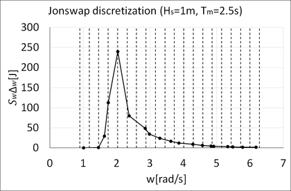
Second, the irregular waves are generated using a Jonswap spectrum (Table 5 and Figure 12). The number of waves used for the discretization is 19, the minimum wave period is 1 s (wmax = 6.283 rad/s), and the maximum wave period is 7 s (wmin = 0.897 rad/s). The frequency interval is then w = 0.283 rad/s. For each wave, instead of using the centre value of the frequency interval, the wave frequency has been selected randomly within the interval in order to avoid short term signal repeatability.
Table 5. Jonswap spectrum discretization.
| Wave Period [s] | Wave Frequency [rad] | Wave Amplitude [m] | Wave Energy [J] |
| 6.227 | 1.009 | 4.37 × 10⁻⁵ | 9.60 × 10⁻⁶ |
| 4.315 | 1.456 | 0.0145 | 1.061 |
| 3.849 | 1.633 | 0.0755 | 28.666 |
| 3.591 | 1.750 | 0.1498 | 112.715 |
| 3.091 | 2.033 | 0.2185 | 239.961 |
| 2.642 | 2.379 | 0.1262 | 79.985 |
| 2.198 | 2.859 | 0.0984 | 48.711 |
| 2.106 | 2.984 | 0.0824 | 34.121 |
| 1.906 | 3.297 | 0.0688 | 23.782 |
| 1.735 | 3.622 | 0.0576 | 16.683 |
| 1.627 | 3.862 | 0.0486 | 11.853 |
| 1.467 | 4.282 | 0.0412 | 8.550 |
| 1.374 | 4.573 | 0.0353 | 6.265 |
| 1.301 | 4.829 | 0.0305 | 4.661 |
| 1.279 | 4.912 | 0.0265 | 3.518 |
| 1.178 | 5.333 | 0.0231 | 2.692 |
| 1.146 | 5.484 | 0.0204 | 2.086 |
| 1.087 | 5.778 | 0.0180 | 1.635 |
| 1.017 | 6.176 | 0.0161 | 1.295 |
| Total wave energy | 628.24 | ||
Figure 12. Jonswap spectrum discretization.
Given the MRAOs and a specific wave scenario, the structural energy response is easily obtained, and most energetic modes can be identified. Using Equation (11), a realization of the modal responses can be quickly obtained. Then, the structural displacement field can be obtained by linear combination of the eigenmodes, and stresses can be calculated using the constitutive model equation (e.g., linear elasticity).
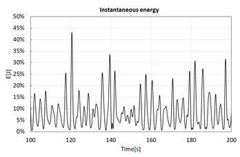
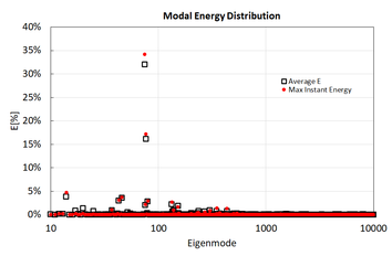
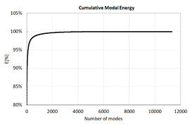
One realization has been carried out for the Jonswap spectrum given in Table 5. Then, the instantaneous modal amplitude and modal energy have been computed for all eigenmodes. Figure 13 provides the instantaneous elastic energy computed as the sum of the elastic energy of all structural eigenmodes. It is observed that the structural energy changes considerably. Since combining the structural response at every time step for all eigenmodes can become very expensive computationally speaking, most energetic time steps can be selected as representative of the most critical ones, reducing this way the amount of calculations is carried out. Figure 14 provides the energy distribution averaged over the simulated time, and the instantaneous energy distribution for time = 120.628 s, where the elastic energy reaches its maximum. It is observed that the energy distribution is quite similar. Figure 15 provides the cumulative energy when ordering eigenmodes from most to least average energy. As was shown in the static case, the number of eigenmodes retaining most of the structural energy is small compared to the total number of degrees of freedom.
Figure 13. Instantaneous elastic energy.
Figure 14. Modal energy distribution. Black square: average energy value over simulation; Red bullet: instantaneous maximum energy (time = 120.628 s).
Figure 15. Cumulative elastic energy ordering eigenmodes by energy.
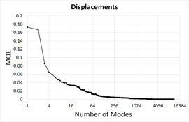
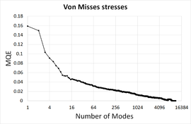
Figure 16 provides the mean quadratic error (MQE) for displacements and Von Misses stresses as a function of the number of modes retained. The error has been normalized with respect to the maximum value.
Figure 16. Convergence of the mean quadratic error (MQE).
5. Conclusions
This work presents a methodology for hydroelastic analysis of floating structures. This methodology is based on a reduced order model of the structural dynamics using the modal matrix reduction (MMR) techniques tightly coupled with a seakeeping hydrodynamics solver (SeaFEM). The methodology has been applied to a buoy, showing that a large reduction in structural degrees of freedom (with respect to a FEM solver) can be performed when projecting on the modal basis and retaining most energetic modes. This reduction justifies the computational effort of computing the modal basis via the eigenmode analysis.
When working under linear loads, modal response amplitude operators (MRAOs) can be obtained. This allows for analysing a large number of different loadcases very quickly once MRAOS have been obtained offline, which justifies the effort of obtaining the MRAOs.
The present methodology can be used, for instance, to determine the fatigue damage of an asset during the design stage. Once MRAOs have been obtained, given the different environmental scenarios and their probability along its lifespan, the structural response is quickly obtained for each scenario.
The linear analysis can be also used to identify the most energetic eigenmodes under specific scenarios, leading to a reduction in degrees of freedom. This reduction can be used to quickly obtain the structural response by linear combination of the modal responses and, also, to create a reduced modal basis to be used under non-linear external loads (such as those coming from mooring systems and wind turbines). Hence, this is very suitable to be implemented in digital twins for structural health monitoring purposes, where assuming linear loads allows one to obtain instant results, and simulations under non-linear loads can be carried out much faster (due to the reduction om degrees of freedom) than computing the dynamic case of a structural FEM solver coupled with a seakeeping solver.
The authors have shown, only for demonstration purposes, how an energy criterion can be used for the selection of modes. The proper level of reduction can be formulated in terms of the elastic energy retained, leading to a significant reduction, even for high levels of energy retention. However, other criteria could be used. Additionally, the level of reduction achieved will depend on the specific problem to deal with. For instance, this is the case if the model is applied for a local analysis on one specific location of the structure. In that case, the selection of those modes that most contribute to that specific location will result in a larger reduction than if details are to be preserved all over the structure.
Funding: This work has been granted by the European Commission under grant agreements H2020 FibreGY (ref. 952966) and H2020 Fibre4Yards (ref. 101006860), and by the Spanish “Ministerio de Ciencia e Innovacion” under grant agreement MLAMAR (ref. PID2021-126561OB-C31).
Acknowledgments: The authors are thankful to all the partners on those projects, and in particular to CompassIS for helping to implement the present methodology on their computational solvers SeaFEM and RamSeries. The authors are also thankful to Joaquín Hernández Ortega for its collaboration on the development of reduced order models, and to Andres Pastor for its contribution on the postprocess of results.
References
1. Jiao, J.; Chen, C.; Ren, H. A comprehensive study on ship motion and load responses in short-crested irregular waves. Int. J. Nav. Archit. Ocean. Eng. 2019, 11, 364–379.
2. Jiao, J.; Jiang, Y.; Zhang, H.; Li, C.; Chen, C. Predictions of ship extreme hydroelastic load responses in harsh irregular waves and hull girder ultimate strength assessment. Appl. Sci. 2019, 9, 240. https://doi.org/10.3390/app9020240.
3. Shin, K.-H.; Jo, J.-W.; Hirdaris, S.E.; Jeong, S.-G.; Park, J.B.; Lin, F.; Wang, Z.; White, N. Two- and three-dimensional springing analysis of a 16,000 TEU container ship in regular waves. Ships Offshore Struct. 2015, 10, 498–509.
4. Kim, Y.; Kim, J.H.; Kim, Y. Development of a highfidelity procedure for the numerical analysis of ship structural hydroelasticity. In Proceedings of the 7th International Conference on Hydroelasticity in Marine Technology, Split, Croatia, 16–19 September 2015; pp. 457–476.
5. Datta, R.; Guedes Soares, C. Analysis of the hydroelastic effect on a container vessel using coupled BEM–FEM method in the time domain. Ships Offshore Struct. 2019, 15, 393–402. https://doi.org/10.1080/17445302.2019.1625848. [15] Oberhagemann, J.; Shigunov, V.; Radon, M.; Mumm, H.; Won, S.I.
6. Jagite, G.; Xu, X.-D.; Chen, X.-B.; Malenica, Š. Hydroelastic analysis of global and local ship response using 1D–3D hybrid structural model. Ships Offshore Struct. 2018, 13, 37–46. https://doi.org/10.1080/17445302.2018.1425521.
7. Oberhagemann, J.; Shigunov, V.; Radon, M.; Mumm, H.; Won, S.I. Hydrodynamic load analysis and ultimate strength check of an 18,000 TEU containership. In Proceedings of the 7th International Conference on Hydroelasticity in Marine Technology, Split, Croatia, 16–19 September 2015; pp. 591–606.
8. Craig, M.; Piro, D.; Schambach, L.; Mesa, J.; Kring, D.; Maki, K. A comparison of fully coupled hydroelastic simulation methods to predict slam induced whipping. In Proceedings of the 7th International Conference on Hydroelasticity in Marine Technology, Split, Croatia, 16–19 September 2015; pp. 575–590.
9. Lakshmynarayanana, P.A.; Temarel, P.; Chen, Z. Coupled fluid-structure interaction to model three dimensional dynamic behaviour of ship in waves. In Proceedings of the 7th International Conference on Hydroelasticity in Marine Technology, Split, Crotia, 16–19 September 2015; pp. 623–636.
10. Jiao, J.; Huang, S.; Wang, S.; Guedes-Soares, C. A CFD–FEA two-way coupling method for predicting ship wave loads and hydroelastic responses. Appl. Ocean. Res. 2021, 117, 102919.
11. Jiao, J.; Huang, S.; Tezdogan, T.; Terziev, M.; Guedes-Soares, C. Slamming and green water loads on a ship sailing in regular waves predicted by a coupled CFD–FEA approach. Ocean. Eng. 2021, 241, 110107.
12. Im, H.I.; Vladimir, N.; Malenica, Š.; Ryu, H.R.; Cho, D.S. Fatigue analysis of HHI SkyBenchTM 19,000 TEU ultra large container ship with springing effect included. In Proceedings of the 7th International Conference on Hydroelasticity in Marine Technology, Split, Croatia, 16–19 September 2015; pp. 561–574.
13. Malenica, S. Hydro structure interactions in seakeeping. In Proceedings of the International Workshop on Coupled Methods in Numerical Dynamics IUC, Dubrovnik, Croatia, 19–21 September 2007.
14. Chen, Z.; Gui, H.; Dong, P. Nonlinear time-domain hydroelastic analysis for a container ship in regular and irregular head waves by the Rankine panel method. Ships Offshore Struct. 2018, 14, 631–645. https://doi.org/10.1080/17445302.2018.1535243.
15. Cummins, W.E. The impulse response function and ship motions. Schiffstecknik 1962.
16. Chen, Z.; Gui, H.; Dong, P. Nonlinear time-domain hydroelastic analysis for a container ship in regular and irregular head waves by the Rankine panel method. Ships Offshore Struct. 2018, 14, 631–645. https://doi.org/10.1080/17445302.2018.1535243.
17. Hess, P. Fluid structure interaction: A community view. MSDL report number: 2016-003. 2016.
18. Garcia-Espinosa, J.; Di Capua, D.; Servan-Camas, B.; Ubach, P.-A.; Onate, E. A FEM fluid–structure interaction algorithm for analysis of the seal dynamics of a Surface-Effect Ship. Comput. Methods Appl. Mech. Eng. 2015, 295, 290–304.
19. Servan-Camas, B.; Di-Capua, D.; Garcia-Espinosa, J.; Sa-Lopez, D. Fully 3D ship hydroelasticity: Monolithic versus partitioned strategies for tight coupling. Mar. Struct. 2021, 80, 103098. https://doi.org/10.1016/j.marstruc.2021.103098.
20. SeaFEM: Theory Manual, Compass IS. Available online: https://www.compassis.com/soporte-seafem/ (accessed on 5 September 2022).
21. Camas, B.S.; Romero, J.G.; García-Espinosa, J. A Time-Domain Second-Order FEM Model for the Wave Diffraction-Radiation Problem. Validation with a Semisubmersible Platform. Mar. Struct. 2018, 58, 278–300. Available online: https://www.scipedia.com/public/Servan_Camas_et_al_2018a (accessed on).
22. Servan Camas, B.; García-Espinosa, J. Accelerated 3D Multi-Body Seakeeping Simulations Using Unstructured Finite Elements. J. Comput. Phys. 2013, 252, 382–403. Available online: https://www.scipedia.com/public/Servan_Camas_Garcia-Espinosa_2013a (accessed on).
23. Mahérault, S.; Derbanne, Q.; Bigot, F. Fatigue damage calculation of ULCS based on hydroelastic model for springing. Ships Offshore Struct. 2013, 8, 289–302. https://doi.org/10.1080/17445302.2012.750087.
Document information
Published on 01/01/2023
DOI: 10.3390/jmse11061168
Licence: CC BY-NC-SA license

