Abstract
This paper presents a family of finite elements for the nonlinear static and dynamic analysis of cables based on a mixed variational formulation in curvilinear coordinates and finite deformations. This formulation identifies stress measures, in the form of axial forces, and conjugate deformation measures for the nonlinear catenary problem. The continuity requirements lead to two distinct implementations: one with a continuous axial force distribution and one with a discontinuous. Two examples from the literature on nonlinear cable analysis are used to validate the proposed formulation for St Venant-Kirchhoff elastic materials. These studies show that displacements and axial forces are captured with high accuracy for both the static and the dynamic case.
1 INTRODUCTION
Cable structures are of great interest in many engineering applications because they offer numerous advantages, such as high ultimate strength, light weight or prestressing capabilities, among others. Nonetheless, a highly nonlinear behavior arises in this type of structures because of their high flexibility. For analyzing cable structures, two families of elements have traditionally been considered: truss elements and catenary elements.
For truss elements, the cable is discretized in a series of straight 2-node elements. In this case, the geometric nonlinearity is often accounted for by a corotational formulation, involving the transformation of the node kinematic variables under large displacements. Truss elements suffer from excessive mesh refinement to obtain accurate results, especially when assuming a constant axial force distribution in the element. Moreover, they may exhibit snap-through instabilities at states of nearly singular stiffness.
Catenary elements use linear kinematics to discretize the cable into a series of curved elements that satisfy the catenary equation. These elements solve the global balance of linear momentum by explicit integration and assuming linear elasticity [1]. As a result, loads are not adjusted with the cable elongation, so that these elements cannot be extended to nonlinear elasticity or inelasticity. Recently, the authors have proposed a general formulation for a catenary element in finite deformations and curvilinear coordinates [2] that overcomes these limitations.
2 MIXED FORMULATION OF THE CATENARY PROBLEM
2.1 Kinematics
Fig. 1 shows the motion of a cable from a reference configuration to a current configuration . Define an orthogonal frame with associated coordinates at any point , such that
|
|
(1) |
where is the parameter describing the curve. Under the motion , this frame is convected to the orthogonal frame . Let upper case letters denote variables in the reference configuration and lower case letters, variables in the current configuration.

|
| Figure 1: Motion of the cable . |
The relevant stretch and Green-Lagrange strain of the problem, in the direction, are
|
|
(2) |
The displacement vector depends only on the curvilinear coordinate ,
|
|
(3) |
Therefore, the relationship between the displacement field and the relevant Green-Lagrange strain can be computed [2] as
|
|
(4) |
It is relevant to observe that the frame is orthogonal, but not orthornomal in general. Indeed, the metric tensor is not necessarily the identity operator and the Green-Lagrange strain may not be physical. Nevertheless, one can construct an orthonormal basis such that
|
|
(5) |
Hence, the components
|
|
(6) |
are physical quantities.
2.2 Equilibrium and principle of virtual work
For expressing the equilibrium equation of the cable in finite deformations, let denote the axial force in the current configuration, thus a Cauchy representation. Observe that the first Piola-Kirchhoff and the Cauchy representations of the axial force coincide for the problem in hand, which does not account for changes in the cross section dimensions.
The Cauchy axial force can be pulled back to the reference configuration to obtain a second Piola-Kirchhoff representation of the axial force, . It can be shown [2] that, using the orthonormal basis in Eq. 5, namely with components and ,
|
|
(7) |
Denoting by and the arc-length coordinates in the current and reference configurations, respectively, the cable distributed load can be described as
|
|
(8) |
Then, global equilibrium for the cable in the current configuration states
|
|
(9) |
where is the material density in the current configuration and , the total acceleration. The corresponding local statement in the current configuration can be obtained with the fundamental theorem of calculus and the localization theorem
|
|
(10) |
or, in the reference configuration,
|
|
(11) |
where represents the dual metric tensor and .
In summary, if is a frame-indifferent constitutive relation between the phy-sical Green-Lagrange strain and the physical 2nd Piola-Kirchhoff axial force , the pair of fields (, ) will be the solution of the cable problem, if and only if, they satisfy
|
|
(12) |
for equivalent to .
The corresponding two-field weak statement of Eq. 12 can be obtained by considering any variation , the space of displacement test functions, any variation , the space of axial force test functions, and integrating the equilibrium equation by parts,
|
|
(13) |
where the constitutive relation is imposed strongly. The spaces for the trial solutions of the displacements and axial forces, and , respectively, are
|
|
(15) |
Similarly, the spaces for the test functions of the displacements and the axial forces, and , respectively, become
|
|
(17) |
where is the Sobolev space for the th weak derivative in the norm.
As a result, there are no continuity requirements for the axial force field . This implies the possibility of exploring cable finite elements with continuous or discontinuous axial force distribution.
3 FINITE-ELEMENT IMPLEMENTATION
3.1 Discretization
The discretization of the governing equations requires interpolations for , and . Assume a -th order Galerkin interpolation for the axial forces
|
|
(18) |
and an -th order Galerkin interpolation for the displacement and acceleration fields
|
|
(19) |
Then, using the same shape functions for the reference configuration, the current configu-ration is obtained as
|
|
(20) |
With these interpolation functions, one can discretize the weak statement in Eq. 13 for a finite element and a time step as
|
|
(21) |
where represents the derivative with respect to the curvilinear coordinate and is the numerical counterpart to .
3.2 Time integration and consistent linearization
Once the discretization of the problem has been performed, the corresponding time-dependent equations need to be solved. As stated before, one can consider cable finite elements with a continuous or a discontinuous axial force field.
3.2.1 Mixed cable element with continuous axial force
For the element with continuous axial force distribution, the cable is subdivided into elements of -th order in axial forces and -th order in displacements. By defining the expanded stress divergence term with components
|
|
(23) |
and the mass matrix as
|
|
(24) |
one can rewrite Eq. 21 in an implicit scheme as
|
|
(25) |
where refers to the external forces considered at the time step .
Introducing Newmark's time integrator [3], one obtains the system of equations
|
|
(32) |
Hence the consistent linearization of the former equation, namely , around a point and for the -th iterate establishes
|
|
(33) |
where the Fréchet derivative corresponds to the dynamic stiffness of the problem, with components
|
|
(34) |
in the form
|
|
(35) |
In order to satisfy stability of the solution scheme, it is necessary [2] that
|
|
(36) |
3.2.2 Mixed cable element with discontinuous axial force
For the element with discontinuous axial force distribution, the cable is also subdivided into elements of -th order in axial forces and -th order in displacements. In this case, however, the axial forces are treated as internal degrees of freedom, and are consequently condensed out at the element level before assembly of the element response. This generates a discontinuity in the axial forces, which is allowed by the condition . The stress divergence term is then understood as
|
|
(37) |
and one can rewrite Eq. 21 in an implicit scheme as
|
|
(38) |
Introducing Newmark's time integrator [3], one obtains the system of equations
|
|
(39) |
Hence the consistent linearization of the former equation, namely , around a point and for the -th iterate establishes
|
|
(40) |
where the Fréchet derivative corresponds to the condensed dynamic stiffness of the problem
|
|
(41) |
with the components defined in Eq. 34.
The stability condition of the solution scheme reads [2] in this case as
|
|
(42) |
4 NUMERICAL EXAMPLES
The proposed formulation is implemented in two cable elements with continuous and discontinuous axial force distributions. The elements, deployed in the general purpose finite element program FEAP [4] and Matlab toolbox FEDEASLab [5], use a linear approximation for the axial forces () and a quadratic approximation for the displacements . The two-dimensional element results in eight degrees of freedom (DOFs), six displacement DOFs and two axial force DOFs, while the three-dimensional element results in eleven DOFs, nine displacement DOFs and two axial force DOFs.
Both elements are implemented with a St Venant - Kirchhoff elastic material model with stored energy in terms of the stretch and the generalized Young's modulus
|
|
(43) |
Thus, if is the area of the cross section and the prestressing force,
|
|
(44) |
with constant material stiffness .
4.1 Example 1: Stability of a 3d pulley system
The first example investigates the stability of a 3d cable supported by a pulley that was previously studied by Impollonia et al [6]. The structural model, whose geometric and material properties are shown in Table 1, consists of a cable anchored at both ends and supported by an intermediate roller. In this case, the inertia forces in Eq. 21 and the mass term of the stiffness are not considered as the problem is analyzed in a static manner.
| Property | Value |
| Cross-sectional area | 805 mm |
| Elastic modulus | 16.0 kN/mm |
| Cable self-weight | 62.0679 N/m |
| Cable length | 500 m |
The objective of this example is to determine the equilibrium configurations of the cable under the assumptions that the pulley is free to move horizontally and that the pulley radius and friction are negligible. For the nonlinear analysis, the cable is subdivided into two segments, one for each span, with the reference curvilinear coordinate of the pulley as problem unknown. This curvilinear coordinate is used to construct the finite element mesh in each iteration.
Following the form finding procedure by Argyris et al [2,7], the analysis starts from a straight reference configuration, and imposes a displacement m at the right support and a pair of displacements m and m at the intermediate roller. Because friction is not considered, the jump in the Cauchy axial force at the roller support must be zero. As a result, the problem is solved by iterating over the curvilinear coordinate so that the jump in the Cauchy axial force at the pulley becomes zero.
| Impollonia et al [6] | Present work (continuous) | Present work (discontinuous) | |
| (m) | 126.12 | 126.26 | 126.25 |
| (kN) | 14.12 | 8.31-13.99 | 8.31-13.99 |
| (m) | 219.98 | 219.46 | 219.47 |
| (kN) | 10.79 | 4.02-10.68 | 4.02-10.68 |
| (m) | 424.76 | 424.70 | 424.70 |
| (kN) | 17.42 | 10.25-17.28 | 10.25-17.28 |
Table 2 summarizes the results for the equilibrium configurations with refering to the curvilinear coordinate of the pulley and , to the axial force. Because the study by Impollonia et al [6] does not consider finite deformations, and correspond to infinitesimal deformations. For the present study, corresponds to the reference confi-guration and , to the Cauchy axial force. While the values of the present study agree well with those by Impollonia et al [6], it is worth noting the variation of the Cauchy axial force that the current formulation captures, as indicated by the range of axial force values in Table 2. In contrast, the model in [6] overestimates the axial force by reporting a value corresponding to the maximum of the current formulation.
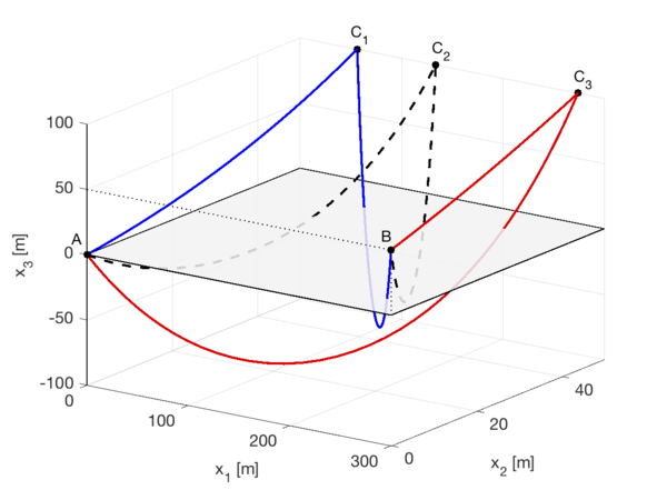
Three equilibrium states result from the analysis, as Fig. 2 shows: three stable confi-gurations denoted with solid lines ( and ), and one unstable configuration, denoted with a dashed line (), as reflected in the change of direction for the horizontal component of the reaction at the pulley. The positions of the pulley for these equilibrium states in Fig. 2 are m, m and m for the continuous and the discontinuous formulations, respectively.
|
| Figure 2: Deformed shape (30 elements) of equilibrium states for Example 1. |
4.2 Example 2: Free vibration in finite deformations
The second example studies the large-amplitude free vibration of two cables with diffe-rent sag/span ratio that were investigated by Srinil et al [8]. The structural model consists of a cable anchored at both ends and spanning 850 m in both cases. Table 3 summarizes the geometric and material properties of the cables denoted by C1 and C2.
| Property | C1 | C2 |
| Cross-sectional area | 0.1159 m | 0.1159 m |
| Elastic modulus | 17.94 GPa | 17.94 GPa |
| Density | 8337.9 kg/m | 8337.9 kg/m |
| Cable length | 840.48 m | 870.51 m |
| Prestressing | - | 345 kN |
First, following the shape finding procedure by Argyris et al [7], the equilibrium confi-guration and the first two natural modes of vibration around this configuration are obtained for both cables by solving the standard eigenvalue problem
|
|
(45) |
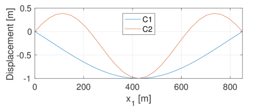
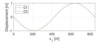
where is the angular frequency, refers to the displacement field at the equilibrium state, and and correspond to the static stiffness and mass matrices of the formulation in Sec. 3.2. Both cables are discretized with a mesh of 14 elements. Results are presented in Table 4, where the end tension is given in the Cauchy representation, and "S" and "A" refer to the symmetric and antisymmetric modes, respectively. Fig. 3 shows the normalized first symmetric and antisymmetric modes of both cables. From this figure, it is interesting to note that, when the sag/span ratio increases, the single extremum for the symmetric mode divides into three because of increasing horizontal displacements.
|
|
| Figure 3: Normalized vertical eigenvectors for Example 2. | |
| C1 | C2 | |||
| Present | Srinil et al [8] | Present | Srinil et al [8] | |
| Sag [m] | 28.01 | 28.39 | 89.28 | 89.57 |
| Sag/span [-] | 1/30 | 1/30 | 1/9.5 | 1/9.5 |
| End tension [kN] | 30432 | 30000 | 10500 | 10500 |
| Frequency (1st S) [Hz] | 0.124 | 0.123 | 0.158 | 0.158 |
| Frequency (1st A) [Hz] | 0.208 | 0.206 | 0.112 | 0.112 |
To evaluate the large-amplitude free vibration, an initial displacement field is imposed corresponding to an amplified first symmetric mode, , where is the normalized first symmetric mode. The parameters for Newmark's method are , and s. No differences are observed between the continuous and the discontinuous formulations as the problem in hand is symmetric in geometry and loads.
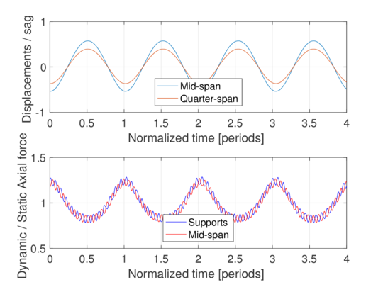
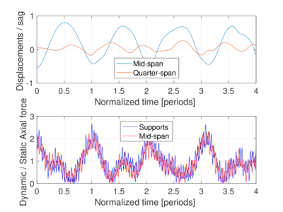
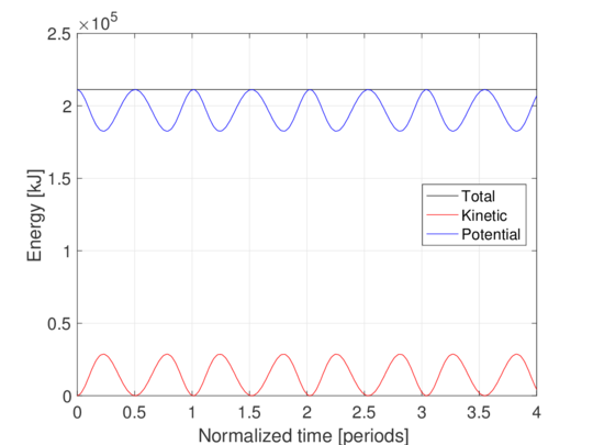
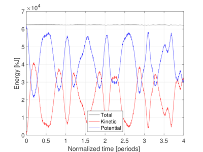
Fig. 4(a) shows the normalized vertical displacements and Cauchy axial forces for cable C1 and . The evolution of the energy for this case is presented in Fig. 5(a). Likewise, Fig. 4(b) and Fig. 5(b) present the normalized vertical displacements and Cauchy axial forces, and energy evolution, respectively, for cable C2 and . While cable C1 behaves linearly in displacements, cable C2 shows a high dependence on high-frequency modes. Also, high-frequency contributions are observed in both cases for the axial force, becoming more relevant for the large sag/span ratio, as observed by Srinil et al [6]. The total energy is conserved for cable C1, whereas it shows minor oscillations for cable C2.
|
|
| Figure 4: Normalized vertical displacements and Cauchy axial forces for Example 2. | |
|
|
| Figure 5: Energy evolution for Example 2. | |
5 CONCLUSIONS
The paper presents a general formulation of catenary elements based on finite deformations and curvilinear coordinates for the nonlinear static and dynamic analysis of cables. From the weak statement of the problem, two implementations are derived: one with a continuous axial force distribution and one with a discontinuous.
As demonstrated by the first example, the formulation is capable of determining equilibrium configurations of three-dimensional cable arrangements with high accuracy, especially in axial forces, compared to other elements in the literature which do not distinguish between Cauchy and 2nd PK axial forces. Furthermore, the second example shows that the natural modes of vibration around equilibrium configurations can also be obtained by the proposed formulation. Because the energy is conserved in the analyzed range of sag/span ratios, Newmark's implicit method can be used to solve the nonlinear dynamic problem. Nevertheless, as observed in the literature, high-frequency contributions in the axial force appear in the analysis, with their amplitude increasing with the sag/span ratio.
In conclusion, because of their consistency and versatility, the proposed catenary elements seem well suited for the nonlinear static and dynamic analysis of nonlinear elastic cables under general loading.
BIBLIOGRAPHY
[1] Andreu, A., Gil, L. and Roca, P. A new deformable catenary element for the analysis of cable net structures. Comp. Struct. (2006) 84:882–1890. [2] Crusells-Girona, M., Filippou, F.C. and Taylor, R.L. A mixed formuation for nonlinear analysis of cable structures. Comp. Struct. (2017) 186:50–61. [3] Newmark, N. A method of computation for structural dynamics. J. Eng. Mech.-ASCE (1959) 85:67–94. [4] Taylor, R.L. FEAP - Finite Element Analysis Program. Univ. of California, Berkeley (2014). http://www.ce.berkeley/feap. [5] Filippou, F. C. FEDEASLab - Finite Elements in Design, Evaluation and Analysis of Structures. Univ. of California, Berkeley (2007). http://www.ce.berkeley.edu/filippou/Courses/FEDEASLab.htm. [6] Impollonia, N., Ricciardi, G. and Saitta, F. Statics of elastic cables under 3D point forces. Int. J. Solids Struct. (2011) 48:1268–1276. [7] Argyris, J. H., Angelopoulos, T. and Bichat, B. A general method for the shape finding of lightweight tension structures. Comp. Meth. Appl. Mech. Eng. (1974) 3:135–149.[8] Srinil, N., Rega, G. and Chucheepsakul, S. Three-dimensional non-linear coupling and dynamic tension in large-amplitude free vibrations of arbitrarily sagged cables. J. Sound Vib. (2004) 269:823–852.
Document information
Published on 28/04/17
Submitted on 27/04/17
Licence: Other
Share this document
Keywords
claim authorship
Are you one of the authors of this document?
