Abstract
This paper aims toward the first step for green campus approach for Indian School of Mines (ISM) campus. Comparative study of the performances for nine different commercialized solar panels made of Maxeon Cell Technology, HIT (Heterojunction with Intrinsic Thin layer), monocrystalline silicon (Mono C-Si), polycrystalline silicon (Poly C-Si), Micromorph, SCHOTT, amorphous silicon (a-Si), CIGS, CdTe technologies in the environmental condition of ISM are presented in this paper. This system suggests to supply the daytime electricity demand of ISM campus as well as efficient use of the huge roof areas of different buildings to setting up the photovoltaic plant. This system ensures a daily mean reduction of 8 MWh electricity consumption from grid. The outcome of this study is that a superior performance is noted for modules made of amorphous silicon technology under the typical temperature variant and dry environmental condition of ISM campus.
Introduction
Inadequate reserves of nonrenewable sources of energy are the cause of serious shortages of energy for most of the countries in the world. Diminution of fossil fuels and gradual emerging consciousness about the environmental degradation lead to main concern of renewable energy resources [1-4]. Green campus is a step toward fossil fuel independency. There are many options available to convert a campus toward a green campus, such as, implementation of wind power, solar power, generation of electricity from waste foods or biomass, plantation of energy seeds, etc. In Indian School of Mines (ISM) campus, maximum wind speed is 2.8 m/sec, observed in the month of May and minimum is 1.4 m/sec in the month of October. The yearly average wind speed in the campus is around 2 m/sec which is not ideally suited for the generation of wind power. In ISM campus, the average waste food produced is 4.5 tonnes/day which is utilized in the fertilizer plant to maintain the greenery of the campus. The soil and climatic condition of the ISM campus are not suitable for plantation of energy seed. The average solar potential on a tilted surface facing toward equator is 5.08 kWh/m2 per day in ISM campus which is ideal to generate solar power. In this paper, only efficient and effective use of unused roof tops for solar photovoltaic (PV) plantation is focused to select the best fitted technology for the concerned site. Grid interactive solar PV systems are gradually becoming more lucrative alternative for electricity generation due to technology improvement, drop in price of balance of system (BOS) in comparison with escalating cost of fossil fuels, and policy upgradation [5, 6]. The performances of PV modules manufactured through unlike technologies are dependent on the environmental conditions. PV modules are rated under standard test condition (STC). These conditions are seldom visualized in the actual field. It is a budding area of research to evaluate the accurate performance of PV system in practical environmental condition.
Previous literatures indicate that behavior of a particular solar module is not only dependent on the material and technology used but also on the environmental conditions at which it is operating. Performance study of unlike PV technologies in different environmental condition is the key for technical mapping of solar PV. Pavlovic et al. [7] compared the total electricity produced from monocrystaline silicon, CdTe, and CIS solar modules of 1 kW capacity PV power plant for 1 year in the climatic conditions of Republic of Srpska. Santana-Rodŕiguez et al. [8] compared the performance of four different solar modules made of monocrystalline silicon, polycrystalline silicon, amorphous silicon, and CdS/CdTe technologies under the environmental conditions of Mexico City. Their study showed a better performance for amorphous silicon technology under the environmental conditions of Mexico City. Daghigh et al. [9] concluded that amorphous silicon performs well under Malaysias tropical hot and humid climate, due to favorable, constant, high solar radiation, and predominant diffuse nature of solar radiation. Makrides et al. [10] concluded that amorphous silicon suffers less from temperature rises, but demonstrates high initial degradation in Cyprus. Adiyabat et al. [11] concluded that PV modules with high temperature coefficient, such as crystalline silicon, are advantageous in the Gobi Desert area. Eke and Demircan [12] analyzed the performance of a multicrystalline Si PV module under Mugla climatic conditions in Turkey.
Technical mapping of solar PV for a particular location is very important and a growing field of research interest around the world. The technical mapping of solar PV concludes that PV technology is best fitted for a particular location. For these reasons, it is required for a particular location. The technical mapping of solar PV for ISM campus is the focus of this paper. The behavior of the electrical parameters of different PV technologies under the specific environment of ISM, Dhanbad is presented here. A comparative analysis of different PV technologies (Maxeon Cell Technology, HIT, Mono C-Si, poly C-Si, Micromorph, SCHOOT, a-Si, CIGS, CdTe) was performed to find out which technology has the best performance under the specific environmental conditions of ISM. Energy consumption trend, electricity bill, meteorological parameter, and rooftop area available for installation of PV panels are also analyzed for the technical mapping of solar PV in ISM campus. Proper utilization of the unused rooftop area for PV plantation will reduce the cost associated with the grid electricity and at the same time it is a wise approach toward green campus.
Methodology
Mathematical Equations used for the technical mapping of Solar PV are discussed in the consecutive section. Energy consumption trend and electricity bills for previous 5 years of ISM campus are analyzed to predict the future energy demand and to emphasize on financial profit as this concept will utilize the unused rooftop areas of the ISM campus. The cost of electricity has already risen 20% since 2009 in India. The related meteorological parameters of ISM campus are collected from National Aeronautics and Space Administration (NASA) renewable energy resource website (Surface Meteorology and Solar Energy). The rooftop areas of different buildings of ISM campus are calculated using AutoCAD software. The investigation was performed based on conventional PV power plant designing method and information obtained from manufacturer datasheets.
Mathematical Equations Required for Technical Mapping
All the mathematical equations related to the performance of PV module are presented consecutively. The daily output of a solar array depends on solar radiation and solar cell temperature.
Effect of temperature on the performance of PV array
The daily output of a solar array depends on solar radiation and PV operating temperature. Rise in the PV operating temperature reduces array peak energy output and the electrical efficiency of solar PV is measured at STC. It is clear that actual evaluation of PV array performance for outdoor field conditions needs to be considered as PV operating temperature of a given location in order to interpret the performance of PV arrays from the standard rating temperature of 25°C to the array performance at actual operating temperature. PV operating temperature can be calculated using measured ambient temperature at a given location, nominal operating cell temperature (NOCT) of the particular technology, and incident solar irradiance on PV array [13-16]. The consequence of including the effects of PV operating temperature in the PV electrical energy output is presented by equations (1) and (2), respectively.
Panel operating temperature
|
|
(1) |
TPO is panel operating temperature in °C; TAMB is ambient temperature in °C; NOCT is nominal operating cell temperature; G is Irradiance in W/m2.
Considering only temperature correction and neglecting Irradiance correction the equation (1) becomes,
|
|
(2) |
So from equation (2), panel operating temperature of a PV technology can be determined if NOCT of that particular PV technology and ambient temperature of the concerned site are known.
Reduction in power output from PV panel due to variation in PV panel temperature from STC
Reduction in panel output due to temperature correction/panel output after temperature correction
|
|
(3) |
RPTC is reduction in power output due to temperature correction in %; γ is temperature coefficient of power for PV panel in %/°C; TSTC is the temperature of the PV module at STC in °C.
Panel output after temperature correction
Panel output after temperature correction,
|
|
(4) |
PTC is panel output after temperature correction in Watt; PMAX is power output at STC in Watt.
Equivalent full sunshine hours in latitude angle tilted surface
Equivalent hours of full sunshine are defined by no. of hours of incident radiation at a place, if intensity of radiation is kept constant at its peak value of 1 kW/m2. Suppose, insolation on a latitude angle tilted unit area surface is expressed by IT kWh/m2 per day, then this can further be expressed as constant peak value of solar radiation of 1 kW/m2 incident on receiving surface for IT hours, then hEFSLAT will be equal to IT h/day. The expression is given by equation (5).
|
|
(5) |
hEFSLAT is equivalent full sunshine hours in latitude angle tilted surface; IT is insolation on tilted surface (for Dhanbad fixed tilt is taken as 23°) in kWh/m2 per day.
Energy from PV panel
|
|
(6) |
ξPanel is energy output from PV panel in Wh; DF is dust factor in %.
Energy output from inverter
|
|
(7) |
is energy output from inverter in Wh; ηinv is inverter efficiency in %.
No. of panels required
|
|
(8) |
NP is no of PV panels; EDC is energy demand of campus (only daytime energy demand is considered).
Active area of single PV panel
|
|
(9) |
L is length of solar panel in m; W is width of solar panel in m.
Base area required for a single panel
|
|
(10) |
ARS is area required for single panel in m2; L is length of solar panel in m; W is width of solar panel in m.
Total base area required for solar PV panels
|
|
(11) |
ART is total base area required for solar PV panels.
Area required for PV plant
|
|
(12) |
ARP is area required for PV plant.
Interrow distance of PV array
Calculation of interrow distance of PV array is needed to prevent interrow shading. Interrow shading refers to the situation where one row of panels shades an adjacent row of panels. A simple rule for minimum spacing between rows is to allow a space equals to three times the height of the top of the adjacent panel [17]. The example in Figure 1 shows that an interspace should be 3h since the height of the adjacent row is h above the front of the next row.
|
|
|
Figure 1. Inter-row spacing of photovoltaic array. |
Interrow distance of PV arrays,
|
|
(13) |
|
|
(14) |
DPV is interrow distance of PV array.
Performance ratio
The performance ratio (PR) is a system performance index that indicates the overall effect of losses on the arrays rated output due to array temperature, incomplete utilization of the irradiation, and system component inefficiencies or failures (IEC 61724). PRs are usually reported on a monthly or yearly basis. PR value calculated for smaller intervals, such as weekly or daily is useful to identify the occurrences of component failures.
|
|
(15) |
PR is performance ratio in %; ηPanel is solar panel efficiency in %.
Energy yield factor
The energy yield factor of the PV system is defined as the portion of the daily net energy output of the entire PV plant which was supplied by the array per kW of installed PV array.
|
|
(16) |
YF is yield factor.
CUF (for a single day)
Sometimes investors or developers use the capacity utilization factor (CUF) to compare the plants performance. The CUF does not take into account any environmental factor like variation in irradiance from 1 year to another or degradation of the panels. CUF for a single day is defined as
|
|
(17) |
CUF is capacity utilization factor for a single day.
Solar charge controller sizing
According to standard practice, the sizing of solar charge controller is to take the short circuit current (Isc) of the PV array, and multiply it by safety factor. The solar charge controller should have enough capacity to handle the current from PV array.
Solar charge controller rating = total short circuit current of PV array × safety factor.
Let us consider safety factor = 1.25.
|
|
(18) |
Isc is total short circuit current of PV array.
Inverter sizing
The input rating of the inverter should never be lower than the total watt of appliances. The inverter size should be 25–30% bigger than total watts of appliances. In case the appliance type is motor or compressor, then the inverter size should be minimum 3 times the capacity of those appliances and must be added to the inverter capacity to handle surge current during starting. For grid tie systems or grid-connected systems, the input rating of the inverter should be same as PV array rating to allow for safe and efficient operation.
For ISM campus, the required inverter size is 2 MVA.
Transformer sizing
|
|
(19) |
Let us consider design margin = 1.1, total load capacity in kVA = 2000 kVA, transformer size = 2000 × 1.1 kVA = 2.2 MVA, selected transformer size is 2.5 MVA, primary voltage = 400 V; secondary voltage = 33 kV.
The daily energy demand of the ISM campus will be 20 MWh by 2015. The solar PV plant will produce nearly 8 MWh, that is, 40% of the daily energy demand.
Cost Analysis
The annual electricity bill of ISM campus in the year of 2014 was Rs. 3,240,916.
Per day average electricity bill = Rs. = Rs. 8879.223.
The yearly available sunny days in ISM campus = 250 days.
The proposed PV plant will supply 40% of the energy demand/day of the campus.
Saving in electricity bill due to generation from solar PV = 8879.223 × 250 × 0.40 = Rs. 887,922.3.
% of Electricity bill saved = × 100% = 27.4%.
By proposed solar PV plant in the campus, 27.4% electricity bill will be saved.
Results and Discussion
Energy consumption of ISM campus
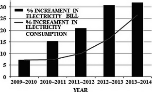
The ISM is an esteemed educational institute in India. It is situated in the coal capital of India, Dhanbad, and coordinated at 23.81°N, 86.44°E. The campus is spread over an area of 393 acres with 218 acres of existing campus and 175 acres under acquisition and expansion. The institute currently has 17 departments and five interdisciplinary centers. The campus comprises the main building popularly known as the Heritage Building, academic buildings, student hostels, Senior Academic Hostel, The Executive Development Centre (EDC), central library, computer centre, Old Lecture Hall Complex, New Lecture Hall Complex, Penman Auditorium, Golden Jubilee Lecture Theatre, and Student Activity Centre. Currently, massive construction activities are in progress in the ISM campus. A new eight-storied central library and a new administration block are under construction. The Senior Academic Hostel and the EDC have also been expanded. ISM has 14 hostels – seven for boys and seven for girls to provide safe and comfortable staying. Due to its existing and expanding huge campus, energy consumption of ISM is also increasing exponentially. Energy consumption of ISM Dhanbad has increased by 7.2%, 7.35%, 9.95%, 16.41%, 26.50%, respectively, from 2009 to 2014 shown in Figure 2.
|
|
|
Figure 2. Energy consumption and electricity bill trend of Indian School of Mines. |
The electricity bill of 2014 is 32% more than 2013. Presently, the electrical load of ISM is 2.0 MW maximum. The entire power of institute is having three DG backup. In 2013–2014 (September 2013 to September 2014), the annual energy consumption of ISM campus was 5.2 GWh. The expected energy demand in 2015 is 7.3 GWh, 40% higher than the previous year. The daily energy demand of the campus will be 20 MWh. Now in this paper, the technical mapping for a grid interactive PV plant is considered, so battery bank is not taken into account. In ISM campus, it is observed that almost 40% load demand is in the daytime and 60% in the night time. As all laboratories, departments and offices are active in daytime, and all hostels and residencies are active in night time, so this type of load pattern is followed. The daily daytime average energy demand is 8 MWh. So, the technology mapping for a grid interactive PV plant that can generate the required daytime energy demand of the campus is the focus of this study.
Analysis of meteorological parameters for ISM campus
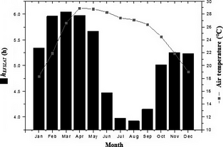
The related meteorological parameters of ISM campus are collected from NASA renewable energy resource website (Surface Meteorology and Solar Energy). The panels are mounted with a fixed tilt of 23° to maximize the annual energy production. The weight of the system and pier depth are two critical design criteria for avoiding deeper pier depths and differential settlement, so a fixed tilt mounting structure is recommended for rooftop. The fixed solar PV plant denotes plant with solar modules mounted on a fixed metal supports under optimal angle in relation to the horizontal surface, and all are oriented toward equator. The fixed tilt systems are lighter in weight, are less expensive, and produce less energy per installed kW on an annual basis than tracking system. The use of tracking system for small solar panels is not recommended due to high energy losses in the driving systems. The power consumption by tracking device is 2–3% of the increased energy [18]. The average solar potential on a tilted surface facing toward equator is 5.08 kWh/m2 per day, which is representative of ISMs conditions. Temperature varies from 18.3°C to 28.9°C in the concerned site with an annual average of 24.9°C. Detail meteorological parameters used for calculation are shown in Figure 3.
|
|
|
Figure 3. Meteorological parameters of Indian School of Mines. |
Figure 3 shows the monthly average equivalent hours of full sunshine on latitude angle tilted surface (hEFSLAT), from which a global average over whole year of 5.08 h/day on the ISM campus of Coal City was calculated. Again, from this figure it is observed that the average hEFSLAT is increased to over 5.8 h/day in the months of February, March, and April. The same is bellow 4 h/day in the month of July and August. Air temperature varies from 18.3°C to 28.9°C in the concerned site with an annual average of 24.9°C. These estimates are important because it provides data representative of ISM campuss specific conditions and it can be used to make projections and sizing of PV systems to be installed in the campus.
On the basis of the collected statistical data, during its first year of work, the direct injection to the grid of the PV system is about 8 MWh/day, which represents the saving of 4.74 equivalent tonnes of coal/day from a coal based thermal power plant. The production of electricity from the proposed solar PV plant will reduce the CO2 emission of 8.73 tonnes/day, as well as other polluting gases and particles if it replaces a coal-based thermal power plant [19]. Considering the results presented in this work, we can project that the installation of PV systems in roofs of ISM campus buildings mean that in the next 10 years thousand tonnes of CO2 would not be emitted to the atmosphere, due to the saving of thousand tonnes of coal used nowadays to produce electricity.
Roof top area calculation
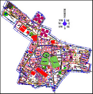
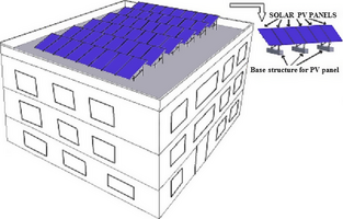
The rooftop areas of different buildings of ISM campus are calculated using AutoCAD software. The rooftop areas for different buildings are classified in four categories, area lesser than 1000, 1000–2000, and 2000–3000 m2 and greater than 3000 m2 are tabulated in Table 1 and shown in Figure 4. AutoCAD view and the suggested PV plant scheme on buildings of ISM campus are shown, respectively, in Figures 5 and 6.
| Area ≥ 3000 m2 | 2000 m2 ≤ Area ˂ 3000 m2 | 1000 m2 ≤ Area ˂ 2000 m2 | Area ˂ 1000 m2 | ||||
|---|---|---|---|---|---|---|---|
| Building name | Area (m2) | Building name | Area (m2) | Building name | Area (m2) | Building name | Area (m2) |
| Academic Block | 4797 | Central Research Facility | 2091 | Centre of Excellence In Safety, Occupational Health And Disaster Management | 1765 | New Health Centre | 700 |
| 600 Room Girls Hostel | 3313 | Me & Mme | 2500 | Science Block | 1226 | Building | 172 |
| Main Building/Heritage Building | 5920 | Petroleum Block (A7 + A7A) | 2970 | Fuel & Mineral Block | 1000 | Dept Of Applied Physics | 318 |
| Academic Complex | 9750 | New Central Library | 2500 | Mine Environment Block | 1300 | HSS/GJLT | 515 |
| Lecture Hall Complex I | 3400 | Diamond Hostel | 2700 | Central Workshop | 1300 | Store Room | 320 |
| Lecture Hall Complex Ii | 4000 | Opal Hostel | 2240 | Central Library | 1237 | Computer Science Block | 705 |
| Amber Hostel | 7500 | Emerald Hostel | 1304 | Management Studies | 966 | ||
| Jasper Hostel | 7500 | Topaz Hostel | 1417 | Geo-Physics | 410 | ||
| Sapphire Hostel | 1916 | New Central Workshop | 986 | ||||
| Ruby Annexe-I | 1109 | Long wall Training Gallery | 930 | ||||
| Ruby Annexe-Ii | 1780 | Seismic Observatory | 40 | ||||
| Admin Block | 1373 | Sports Centre | 890 | ||||
| Executive Development Centre | 1026 | Research Scholar Hostel | 180 | ||||
| Indian School Of Learning | 1026 | Ruby Hostel-I | 807 | ||||
| Residences-Type 1 & 2 | 1543 | Ruby Hostel-Ii | 153 | ||||
| Residences-Type 3 | 1292 | Shanti Bhawan | 297 | ||||
| Residences-Type 4 | 1479 | Senior Academic Hostel | 621 | ||||
| Residences-Type 5 | 1823 | Campus Administration | 427 | ||||
| Ncc Office | 220 | ||||||
| Canteen | 296 | ||||||
| Teacher Club | 200 | ||||||
| Staff Club | 260 | ||||||
| Directors Residence | 483 | ||||||
| Registrars Residence | 200 | ||||||
| L Mos Residence | 208 | ||||||
| S Mos Residence | 190 | ||||||
| Health Centre | 390 | ||||||
| Residences-Type 6 | 797 | ||||||
| Old Mess Building | 520 | ||||||
| Total | 46,180 | Total | 15,001 | Total | 24,916 | Total | 13,201 |
|
|
|
Figure 4. % Contribution by different rooftop areas of Indian School of Mines campus. |
|
|
|
Figure 5. AutoCAD view of Indian School of Mines campus. |
|
|
|
Figure 6. Proposed rooftop PV plant Scheme for ISM campus. PV, photovoltaic; ISM, Indian School of Mines. |
It is observed from the study that 46.51% area of the total available rooftop area, that is, 99,298 m2 is contributed by the building with rooftop area greater than 3000 m2. The rooftop area contributed by buildings having rooftop area lesser than 1000 m2 is 13.29%. About 25.09% rooftop area of the total rooftop area is from buildings with 1000–2000 m2 area. Only 15.11% of the total rooftop area is contributed by the buildings with 2000–3000 m2 area.
Technology selection
In this paper nine commercialized PV technologies are selected for technical mapping to find out the best suited technology for ISM campus. Specifications of the selected PV technologies are collected from their datasheets. The required specification of the selected PV technologies is enlisted in Table 2.
| Manufacturer | Module type | Technology | PMAX (W) | Temp coefficient (%/°C) | NOCT (°C) | Panel length (m) | Panel width (m) |
|---|---|---|---|---|---|---|---|
| Sun Power | SPR-435NE-WHT-D | Maxeon Cell Technology | 435 | 0.38 | 45 | 2.067 | 1.046 |
| SANYO Electric Co., Ltd. | HIT-H250E01 | HIT | 250 | 0.3 | 46 | 1.61 | 0.861 |
| Helios Solar | Helios Solar 9T6-420 | Monocrystalline | 420 | 0.41 | 45 | 1.976 | 1.31 |
| Conergy | PE-300 | Polycrystalline | 300 | 0.43 | 47 | 1.956 | 0.991 |
| Silevo Triex | Silev o Triex -U300 Black | Micromorph (Mono C-Si and amorphous silicon hybrid) | 300 | 0.27 | 46 | 1.586 | 1.056 |
| SCHOTT Solar | SCHOTT PROTECT™ ASI CLIME Serie 116 | SCHOTT | 116 | 0.2 | 49 | 1.308 | 1.108 |
| Sungen International Limited | SG-HN105-GG | a-Si | 100 | 0.268 | 40.28 | 1.4 | 1.1 |
| Stion | STO-150 | CIGS | 150 | 0.26 | 45.6 | 1.656 | 0.656 |
| First Solar | FS-385 | CdTe | 85 | 0.25 | 45 | 1.2 | 0.6 |
Technology comparisons of different PV modules under the environmental conditions of ISM campus
The comparisons of different parameters for nine different technologies are shown consecutively in this section.
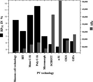
The percentage decrement in power output due to temperature and area required for power plants of different technologies is shown in Figure 7. From Figure 7, it is very clear that RPTC is minimum for a-Si with 5.41% and maximum for Poly C-Si with 11.57%. Reduction in power output due to temperature correction (RPTC) for Maxeon Cell Technology, HIT, Mono C-Si, Poly C-Si, Micromorph, SCHOTT, CIGS, CdTe technologies is, respectively, 21.78%, 30.40%, 47.02%, 53.24%, 22.66%, 6.43%, 18.43%, 13.12% greater with respect to a-Si technology. It is seen that the area required (ARP) for PV plant made of Maxeon Cell Technology is minimum, 17,063.5 m2, whereas maximum 50,603.85 m2 areas required for a-Si technology. The area required for plants made of Maxeon Cell Technology, HIT, Mono C-Si, Poly C-Si, Micromorph, CIGS, CdTe technologies is respectively 33.72%, 36.93%, 42.16%, 44.88%, 36.87%, 47.64%, and 55.48% of the area required for a-Si plant.
|
|
|
Figure 7. PRTC and ARP comparison of different photovoltaic technologies. |
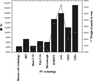
The no. of panels required and the total weight of panels for different PV technologies are shown in Figure 8. The maximum number of panels, 21,180 is required for CdTe technology, whereas minimum, 4286 is required for Maxeon Cell Technology. The total weight of panels for Maxeon Cell Technology is 1088.77 tonnes which is minimum among all the technologies concerned here. The total weights of PV panels are maximum for a-Si technology with 25,301.92 tonnes. The total weight comparison is required to justify that the rooftop area is capable of taking that weight.
|
|
|
Figure 8. NP and panel weight comparison for different photovoltaic technologies. |
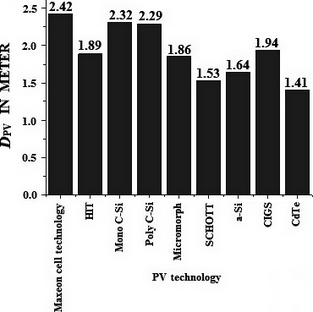
The interrow spacing of PV arrays (DPV) is shown in Figure 9. The maximum DPV (m) is for Maxeon Cell Technology as the length of panels is maximum for this technology. The minimum DPV is observed for CdTe technology as its panel length is minimum. The Interrow spacing is not too much important for technical mapping and it only gives us an idea about the requirement of area for different technologies.
|
|
|
Figure 9. Interrow array spacing comparison for different photovoltaic (PV) technologies. |
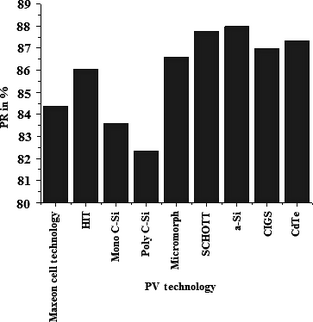
PRs for nine different PV technologies are shown in Figure 10. The highest PR of 87.98% is seen for a-Si Technology as its reduction in power output due to temperature variation is minimum. PR of Poly C-Si technology is minimum with a value of 82.31%. PR values of Maxeon Cell Technology, HIT, Mono C-Si, Poly C-Si, technologies are 4.10%, 2.21%, 5.01%, and 6.44%, respectively, lesser than a-Si technology. PR values of a-Si, SCHOTT, CIGS, CdTe technologies are very close to each other. Low PR of Poly C-Si is due to the effect of temperature variation in power output.
|
|
|
Figure 10. PR Comparison for different PV technologies. PR, performance ratio; PV, photovoltaic. |
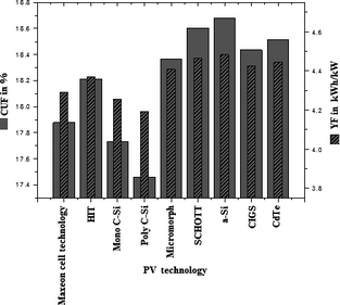
The CUF and energy yield factor (YF) for the nine different technologies are shown in Figure 11. It is observed that CUF and YF are maximum for a-Si technology with a value of 18.68% and 4.48%, respectively. The minimum values of these two parameters are seen for Poly C-Si technology due to the effect of temperature. The CUF and YF values of Maxeon Cell Technology, HIT, Mono C-Si, Poly C-Si, technologies are respectively 4.29%, 2.50%, 5.08%, and 6.51% lesser than a-Si technology. The same is only 1.68%, 0.39%, 1.29%, and 0.86% lesser compared to a-Si technology for Micromorph, SCHOTT, CIGS, CdTe technologies, respectively. The finding from this work is tabulated in Table 3.
| Technology | RPTC | NP | ART | ARP | WT | DPV | PR | CUF | YF |
|---|---|---|---|---|---|---|---|---|---|
| |||||||||
| Maxeon Cell Technology | 9.46 | 4286 | 8531.75 | 17,063.50 | 1088.77 | 2.42 | 84.37 | 17.88 | 4.29 |
| HIT | 7.77 | 7322 | 9343.36 | 18,686.71 | 1208.08 | 1.89 | 86.03 | 18.21 | 4.37 |
| Monocrystalline | 10.21 | 4477 | 10,667.49 | 21,334.98 | 1401.15 | 2.32 | 83.57 | 17.73 | 4.26 |
| Polycrystalline | 11.57 | 6363 | 11,355.15 | 22,710.31 | 1431.76 | 2.29 | 82.31 | 17.46 | 4.19 |
| Micromorph | 6.99 | 6050 | 9328.60 | 18,657.19 | 1149.58 | 1.86 | 86.60 | 18.36 | 4.41 |
| SCHOTT | 5.78 | 15,446 | 20,607.84 | 41,215.69 | 3212.81 | 1.53 | 87.76 | 18.60 | 4.46 |
| a-Si | 5.41 | 17,847 | 25,301.92 | 50,603.85 | 4640.26 | 1.64 | 87.98 | 18.68 | 4.48 |
| CIGS | 6.63 | 12,054 | 12,054.57 | 24,109.14 | 2025.04 | 1.94 | 86.98 | 18.44 | 4.42 |
| CdTe | 6.23 | 21,180 | 14,038.24 | 28,076.48 | 2541.54 | 1.41 | 87.35 | 18.52 | 4.44 |
|
|
|
Figure 11. CUF and YF comparison for different PV technologies. CUF, capacity utilization factor; YF, yield factor; PV, photovoltaic. |
From Table 3, it is observed that the effect of temperature on a-Si technology is minimum among the nine selected PV technologies and PR, CUF and YF are also maximum for this technology due to lesser effect of temperature on this technology. But the total no of panel required is the second highest after CdTe technology, but cost of a-Si technology is lesser compared to other technologies like Maxeon Cell Technology, HIT, Mono C-Si, Poly C-Si, Micromorph. Consequently, the area requirement and the total weight of panels are maximum for this technology. So if adequate land area, as seen by calculation, and , enough rooftop area are available for PV plant installation in ISM campus, then a-Si technology is the best for our concerned site. But if land area is a problem, then the best fitted technology will be Maxeon Cell as the land area requirement is minimum for this technology and other parameters are also good enough. If slightly more land area than Maxeon Cell technology is permissible then HIT is the best fitted for the concerned site. The land area required for HIT technology is 9.51% more, but the effect of temperature is 21.78% lesser than the Maxeon Cell Technology. The spacing between PV arrays for HIT technology is also 28.39% lesser, PR and YF are, respectively, 1.97% and 1.87% more compared to the Maxeon Cell Technology. It can be concluded that the best suited technology for ISMs environmental condition is a-Si, but if land area is a barrier then the HIT technology is the second best and after that the Maxeon Cell Technology can be chosen. As from the study of rooftop area, it is very clear that land availability in ISM campus for PV plant installation is more than enough so a-Si is the best for the concerned site and also its cost is lesser compared to other PV technologies. The total rooftop area available for PV plant installation in ISM campus is much more than the required area calculated for installation. If only the rooftop areas greater than 2000 m2 are considered then also it is 61,181 m2 that is, much more than the maximum area 50,604 m2 required for the installation of a-Si PV plant. So, the rooftop area is not a barrier for installation of PV power plant to supply the daytime energy demand of ISM campus.
Conclusions
The encouragement of energy-efficient appliances and tighter government restrictions on thermal power plants has attracted the use of grid-connected PV systems in a modern utility. The grid- connected PV system can directly feed energy into the existing AC grid system, where the cost of batteries for energy storage can be reduced. In this paper, by analyzing the energy consumption of the campus, climatic conditions, and the available land area, critical observations are as follows:
- Solar power is selected as the best suited technology for Green campus approach of ISM.
- By comparing nine available PV technologies, it is observed that a-Si is best suited in terms of power losses, land requirement, PR, CUF, YF, and cost.
- If only the rooftop areas greater than 2000 m2 are considered then also it is 61,181 m2, that is, much more than the maximum area 50,604 m2 required for installation of a-Si PV plant.
- Total energy generation using solar PV technology is about 8 MWh/day which supplies 40% of the net energy demand/day of the ISM campus.
- Utilizing solar PV it may the reduce electricity bill around 27.4% of the existing annual energy bill.
Conflict of Interest
None declared.
References
- Hacatoglu, K., I. Dincer, and M. A. Rosen. 2014. A new model to assess the environmental impact and sustainability of energy systems. J. Clean. Prod. In press. doi: 10.1016/j.jclepro.2014.06.050
- Hosseini, S. E., and M. Abdul Wahid. 2014. The role of renewable and sustainable energy in the energy mix of Malaysia: a review. Int. J. Energy Res.38:1769–1792.
- Guo, K. W.2012. Green nanotechnology of trends in future energy: a review. Int. J. Energy Res.36:1–17. doi: 10.1002/er.1928
- Farhat, A. A. M., and V. I. Ugursal. 2010. Greenhouse gas emission intensity factors for marginal electricity generation in Canada. Int. J. Energy Res.34:1309–1327. doi: 10.1002/er.1676
- Lund, P. D.2009. Effects of energy policies on industry expansion in renewable energy. Renewable Energy34:53–64.
- Paatero, J. V., and P. D. Lund. 2007. Effects of large-scale photovoltaic power integration on electricity distribution networks. Renewable Energy32:216–234.
- Pavlovic, T. M., D. D. Milosavljevic, D. Mirjanic, L. S. Pantic, I. S. Radonjic, and D. Pirsl. 2013. Assessments and perspectives of PV solar power engineering in the Republic of Srpska (Bosnia and Herzegovina). Renew. Sustain. Energy Rev.18:119–133.
- Santana-Rodŕiguez, G., O. Vigil-Galan, D. Jimenez-Olarte, G. Contreras-Puente, B. M. Monroy, and A. Escamilla-Esquivel. 2013. Evaluation of a grid-connected photovoltaic system and in-situ characterization of photovoltaic modules under the environmental conditions of Mexico City. Rev. Mex. Fis.59:88–94.
- Daghigh, R., A. Ibrahim, G. L. Jin, M. H. Ruslan, and K. Sopian. 2011. Predicting the performance of amorphous and crystalline silicon based photovoltaic solar thermal collectors. Energy Convers. Manage.52:1741–1747.
- Makrides, G., B. Zinsser, G. E. Georghiou, M. Schubert, and J. H. Werner. 2010. Evaluation of grid-connected photovoltaic system performance losses in Cyprus, in 7th Mediterranean Conference and Exhibition on Power Generation, Transmission, Distribution and Energy Conversion, Volume 2010, Issue 572 CP.
- Adiyabat, A., K. Kurokawa, K. Otani, N. Enebish, G. Batsukh, M. Battushig, et al. 2006. Evaluation of solar energy potential and PV module performance in the Gobi Desert of Mongolia. Prog. Photovoltaics Res. Appl.14:553–566.
- Eke, R., and H. Demircan. 2013. Performance analysis of a multi crystalline Si photovoltaic module under Mugla climatic conditions in Turkey. Energy Convers. Manage.65:580–586.
- Ross, R. G.1976. Interface design considerations for terrestrial solar cell modules. Pp. 801–806in Proceedings of the 12th IEEE photovoltaic specialists conference, Baton Rouge, LA, 15–18 November 1976.
- Skoplaki, E., and J. A. Palyvos. 2009. Operating temperature of photovoltaic modules: a survey of pertinent correlations. Renewable Energy34:23–29.
- Garcia, A., and J. Balenzategui. 2004. Estimation of photovoltaic module yearly temperature and performance based on nominal operation cell temperature calculations. Renewable Energy29:1997–2010.
- Malik, A., and S. J. B. H. Damit. 2003. Outdoor testing of single crystal silicon solar cells. Renewable Energy28:1433–1445.
- Dunlop, J.2003. Study guide for photovoltaic system installers and sample examination questions. Florida Solar Energy Centre. Publication No: FSEC-GP-274-03.
- Mousazadeh, H., A. Keyhani, A. Javadi, H. Mobli, K. Abrinia, and A. Sharifi. 2009. A review of principle and sun-tracking methods for maximizing solar systems output. Renew. Sustain. Energy Rev.13:1800–1818.
- Ghodke, S., R. Kumar, N. Singh, and H. Khandelwal. 2012. Estimation of green house gas emission from Indian coal based thermal power plant. IOSR J. Eng.2:591–597.
Document information
Published on 01/06/17
Submitted on 01/06/17
Licence: Other
Share this document
Keywords
claim authorship
Are you one of the authors of this document?

