ABSTRACT
This chapter presents the composite materials applied to Water Current Turbine (WCT) hydrokinetic turbines. Here will be briefly described the features of these turbines, the fluid-dynamic behavior of the rotor, and its structure formed into a composite material. From the structural viewpoint an advanced composite material formulation that allows an appropriate structural design is introduced. The generalized composite formulations here introduced take into account the nonlinear mechanical behavior of the component materials (matrix and fiber), as the local behavior of plasticity and damage, its anisotropy, the fiber matrix debonding, its material composition via a general mixing theory, and also the homogenized structural damage index definition.
Hydrokinetic turbines bring newer advantages and greater possibilities for green hydroelectric power generation. For this reason, achieving a very high lift blade rotor to take the maximum kinetic energy advantage for rivers with a slow velocity flow is very important. A very low inertia rotor permits a self-starting effect for the axial water flow turbine to take the maximum advantage of the river kinetic energy which is very important in this kind of devices. A turbine rotor hydrofoil made in composite material can be designed for this purpose.
One of the most commonly used composite material analysis formulation is herein introduced. Specifically, a particular Serial/Parallel (S/P) Mixing Theory with a better relation between model accuracy vs. computational cost is provided. In front to other formulation, the S/P Mixing Theory not increasing the degrees of freedom of the problem because is a constitutive formulation.
A brief introduction to fluid-dynamic concept involving in the analysis of a rotor of this type of turbines is presented. This allows seeing the origin of the actions applied to the rotor of this type of turbines.
In addition, two simple examples that show the potentiality of the model are presented in this chapter. Then, an application to the design of a rotor blade of a passing turbine, made of carbon fiber-reinforced matrix composite material, is shown.
1
General Introduction
According to United Nations, 20% of the global population does not have access to electricity, and a further 14% lack reliable access [54]. The use of an axial flow rotor turbine in remote area was claimed to have for pumping irrigation and electrical power generation. Hydrokinetic turbines bring newer, greater possibilities and advantages for hydroelectric power generation. There are applications in water currents of 0.5 m/s in more [53]. Development of renewal energy production in rivers and channels still preserve a very interesting power production potential, being not subjected to the classical hydraulic power exploitation. This solution avoids the construction of expensive dams and reduces considerably the environmental impact produced by classical hydropower generation [52]. Low speed flux and lack of depth are the main obstacles in hydrokinetic operation. For this reason, achieving a very high lift rotor to take the maximum advantage of the kinetic energy of a slow velocity water flow, which belongs to a lowland river type, is a very important topic. The use of a high lift aerodynamic/hydrodynamic profile and composite material for the blades serve to accomplish the task.
The main purpose of this chapter is to describe a general procedure to achieve a very low inertia rotor minimizing the start-stop effect for the axial water flow turbine, in which is important to take the maximum advantage of the kinetic energy. The composite hydrofoil of the turbine rotor can be designed using reinforced laminate composites, to obtain the maximum strength and lower rotational-inertia. The mechanical and geometrical parameters involved in the design of this fiber-reinforced composite material are the fiber orientation, number of layers, stacking sequence and laminate thickness.
For this reason, it will be briefly described the features of hydrokinetic turbines (WCT - Water Current Turbine) for river use, their basic design requirements and the response by using matrix-reinforced composite structures. Design requirements for these turbines need a numerical process simulation of the fluid dynamic problem coupled with the behavior of the structure made of composite materials. From the structural viewpoint it is necessary the use of an advanced composite material formulation that allows an appropriate structural design. For this purpose, a "mixing theory" [1,2,7,8,27,29,30,31,32,38,39,42,50] and / or "homogenization theory" [3,4,5,9,43,47,48,49,51] of simple substances are used, with a mapping spaces formulation [6] that allow considering the anisotropy of the constituent and composite materials in the most general possible way, and a fiber matrix debonding formulation [2,29,31,39]. Moreover, within these general formulations, it is also taken into account the nonlinear mechanical behavior of the component materials (matrix and fiber), which allows to know precisely the limits of participation of each one of them into the composite.
The study of composite materials has been one of the major objectives of computational mechanics in the last decade. The numerical simulation of orthotropic composite materials has been done by means the average properties of their constituents, but this approximation, no model has been found able to work beyond the constituents elastic limit state. Thus, these procedures are limited to the numerical computation to elastic cases. Different theories have been proposed to solve this problem, taking into account the internal configuration of the composite to predict its behavior. The two most commonly used are herein remarked.
- Homogenization theory: This method deals with the global problem of composite material in a two-scale context. The macroscopic scale uses the composite materials to obtain the global response of the structure; composites are considered as homogeneous materials in this scale. The microscopic scale corresponds to an elemental characteristic volume in which the microscopic fields inside the composite are obtained; this scale deals with the component materials. Homogenization theory assumes a periodical configuration of the composite material to relate these two scales [3,4,5,9,43,47,48,49,51].
- Mixing theory: The first formulation of the mixing theory corresponds to Trusdell and Toupin [7] and it is based in two main hypothesis: 1. All composite constituents have the same strains. 2. Each constituent collaborates to the composite behavior according to its volumetric participation. The main problem of the mixing theory is the iso-strain condition, which forces a parallel distribution of the constituents in the composite. Some improvements to the original formulation can be found in [1,2,7,27,29,30,31,32,38,39,42,50].
In this chapter a brief introduction to the “Serial / Parallel theory of mixtures”, a more advanced formulation than the classic one, is presented. The election of the mixing theory instead of a homogenization theory is based in the better relation between model accuracy vs. computational cost provided by the former one [5]. A homogenization theory requires a micro-model for each point of the structure that becomes non-linear. Despite the advances made in strategies to reduce the amount of micro-models solved [9,44,46,48,51], the resolution of a real structure with this procedure generates such a big amount of degrees of freedom that the calculation is beyond the computation capabilities of nowadays personal computers. On the other hand, the mixing theory does not increase the degrees of freedom of the problem, as it is only present in the constitutive section of the finite element code.
2 Hydrokinetic Turbines - Introduction
This section provides an overview of a "Water Current Turbine" (WCT) allowing understand the hydrodynamic basis for their design and its requirements for the structural function [10,11,12,13,14,15,16,15]. Then, Section 5 presents the basis for the analysis of its structure made up in a reinforced composite material, and a simple application in the examples section are shown too.
Rivers kinetic energy for electric power generation is a very valuable alternative source. This emerging class of renewable energy technology, the hydrokinetic conversion device (HCD), offers ways to capture the energy of flowing water without the impoundment or diversion of the conventional hydroelectric facilities based on dams and penstocks. Hydrokinetic technologies are designed for deployment in natural streams, like rivers, tidal estuaries, ocean currents, and in some constructed waterways [10,11,12,13,14,15,16,15]. As opposed to the rigid, expensive, and environmentally aggressive construction of tidal barrages, the modularity and scalability of hydrokinetic devices are attractive features [11].
River streams and other artificial channels have potential for generating electric power through several hydrokinetic energy technologies. This nascent class of renewable energy technology is being strongly considered as an exclusive and unconventional solution falling within the area of both in-land water resource and marine energy [12]. Conventional large or small hydroelectric systems use reservoirs and penstocks to create an artificial water head and extract the potential energy of downwardly falling water through suitable turbo-machinery. In contrast, a river turbine, which could be built as a free-rotor or part of a channel augmented system, may provide an effective alternative mean for generating power. Such systems would potentially require little or no civil work, causing less environmental impact [13,14].
Khan, Iqbal and Quaicoe [13] showed values that indicate the possibility of higher energy capacity through a river turbine when compared to an equally sized wind energy converter. Wind turbines are usually designed to operate with rated wind speed of 11–13 m/s while, in contrast, river turbines with augmentation channels could be designed for low effective water velocities of 1.75–2.25 m/s or even higher, depending on site resources.
Unlike wind energy, the size of these engines is a limitation for this type of energy generation and must be reduced according to the river depth. Another drawback is the low flow velocity, and it requires a set of blades and rotor with a specific design to generate the greater amount of kinetic energy as possible from the water flow [15].
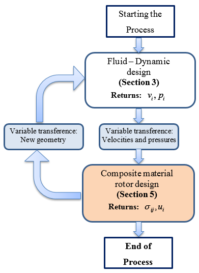
This chapter describes a general procedure for an efficient fluid-mechanical design of the rotor´s blades. The use of high lift airfoils, and composite materials structural design for low rotational inertia, guarantees the hydrodynamics efficiency. Thus, the chapter is structured taking into account the analysis of this axial hydrokinetic river turbine as the fluid dynamic design of the rotor turbine; and the structural design of the rotor by composite materials. These areas converge in a multidisciplinary methodology depicted in Figures 5.
3 Rotor hydrokinetic turbine design. Fluid-Solid interaction
Hydrokinetic turbines, unlike conventional hydraulic turbines utilize the kinetic energy of river/channels water for power generation. The performance of these turbines depends of the number of blades, tip speed ratio, type of airfoil, blade pitch, chord length and twist and its distribution along the blade span [55].
Knowing the inlet and outlet pressure in the micro-scale volume control (VC1), a procedure for the rotor design of a hydrokinetic turbine for riverbed operation is described in this section. The study is focused on the conditions of a standard large-medium sized lowland river. The structural analysis of this rotor engineered in composite materials with reduced inertia and better functionality for low speed currents fluvial beds, is described in Sections 4 and 5. The results of the numerical simulation of the composite rotor structure can also be found in the Section of examples.
3.1 Hydrofoil profile and rotor
Inside of the micro-scale control volume (VC2) a composite material rotor turbine is placed. A brief hydrofoil design of its profile is here presented.
The supplied turbine power is directly proportional to the machine’s operating angular speed and its torque produced at that specific speed,
|
|
(1) |
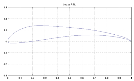
If more lift is obtained by one blade, more torque and angular velocity will be obtained by the turbine. This commitment is achieved by selecting the S1223 foil [16], which belongs to the high lift low Reynolds profiles class (see Figure 1). Initially designed as an airfoil for air working conditions, the S1223 profile has also been tested as a hydrofoil under water conditions operation, showing very good operational qualities [17]. A rotor with S1223 hydrofoil profile keeps the proper balance between lift and drag and maintains an attached flow in the hydrofoil neighborhood. In consequence, this rotor has a better pressure distribution and presents hydrodynamic stability, preventing interference with the rest of the hydrofoils forming the rotor.
3.2 Simplified hydrofoil analytical pre-design
For turbine application, hydrofoil must be designed starting from the premise that it has to maintain fluid mechanics parameters (such as angle of attack, homogeneous pressure distribution, etc.) along the whole wingspan, despite the fact that rotary operating conditions produce different linear velocity of rotation ( ) along the blade axis (which gets higher the nearer the point is from the wingtip). Working with this condition involves the variation of the blade geometry parameters (like camber angle, airfoil chord, etc.) in relation with the wingspan axis. Figure 2 shows the notation for angles and velocities on the blade profile, where is the absolute flow velocity in the micro-scale VC2 volume control, represents the blade’s linear rotational speed and is the relative flow velocity.
The angle of attack α is an aero-hydrodynamic angle defined between and the airfoil chord, and depends on the airfoil profile and its camber angle β. Instead, camber angle β represents a mechanical angle, defined between the hydrofoil chord and its plane of rotation. By combining hydrodynamics and mechanical angles, the sustentation angle ( ) appears which is very useful to obtain the variation camber angle in a rotating blade.
Parameters involving the use of a S1223 profile working as a non-twisted, non-rotatory and unturbined designed hydrofoil are explained below [17]. The suitable angle of attack occurs at the optimum angle of attack , which is considered as a starting parameter of the design sequence; it involves lift coefficient and drag coefficient . Lift coefficient can raise until it reaches its maximum at , but beyond that angle, detachment of the boundary layer will happen, dropping lift coefficient and increasing drag coefficient enormously [18].
The Tip Speed Ratio (TSR or ) is a non-dimensional parameter that is defined by taking the relationship between the absolute river flow axial flow velocity and the blade speed turbine rotor , and it is given by
|
|
(2) |
where is the rotor radius. According to Betz´s law [19], turbine mechanical power specified for axial turbines depends on the flux density ρ and flow speed in VC2 volume control; both values are fixed by the river flow, and so these parameters are fixed as initial conditions and will not be modified during the process of the rotor design. According to this, rotor nominal power can be established, and is computed from
|
|
(3) |
The swept area ( ) is the unique variable in Equation (3), and it depends (radius of the rotor).
Despite the rotating condition, it is necessary to maintain the angle of attack along the wingspan; this scenario permits to keep the rotor’s fluid dynamic stability. These commitments are accomplished by varying the geometry parameters of the hydrofoil chord size and camber angle , along the wingspan. To achieve this goal the Blade Element Theory can be used; according to Froude [20,21], the airfoil´s total length ( ) is split in several segments, and each one is designed individually as (Figure 3). Sustentation angle (Figure 2) is obtained by means of Equation (4), as follows:
|
|
(4) |
The chord size of the airfoil is therefore computed for each segment by
|
|
(5) |
where is the actual number of airfoils in the rotor, is the lift coefficient corresponding to a defined profile section at a certain radius , and the airfoil shape factor can be computed by a curve approximation given by
|
|
(6) |
In Equation (6) the non-dimensional parameter is given by
|
|
(7) |
As a result of the chord modification during the process by Equation (5), the initial attack angle has to be recalculated too through Equation (9), obtaining a new angle of attack for each chord in each segment . For this recalculation, the parameter, which represents a relationship between the wingspan and the average of the chord, is necessary,
|
|
(8) |
As the length camber and the chord angles have been modified for each wingspan segment, the angle of attack must be verified for each section through the following expression:
|
|
(9) |
Solving from Equation (2) to Equation (9), the airfoil parameters can be obtained. These parameters allow the definitive design of the turbine blade. Blade parameters are strictly germane with the rotor composition through Equation (10), which represents the ideal number of blades included in the rotor according to flow and geometry parameters. A higher torque on turbine will be obtained if a higher number of blades will be included in the rotor. This condition also simplifies the starting of the turbine, ergo is a good design requirement to have the more possible number of hydrofoils in the rotor
|
|
(10) |
3.3 Brief comment about the 3-D fluid-dynamic numerical simulation of the hydrofoil blade.
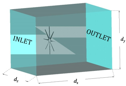
An ideal representation of the working turbine operation can be performed by a numerical simulation. The model is a confined fluid domain ( ) rendering the underwater operation without free surface (VC2). The hydrofoil rotor is located inside that control volume that is made from a box of appropriate measures, as shown in Figure 4. The dimensions are chosen so as a steady flow is needed at the boundaries of the box. Flow with direction will cross from the inlet surface to the outlet surface. The rest of domain surfaces have wall condition.
Fluid mechanics governing equations for incompressible flows ( ) involves mass conservation condition (Equation (4)),
|
|
(11a) |
and Navier-Stokes equation [18,29],
|
|
(11b) |
where is the velocity field inside the VC2 control volume.
Notice that the governing equations system is constituted by four equations and four unknowns, which are pressure and the three vector components of the field velocity; so numerical techniques are necessary for this treatment. A Finite Element Variational Multiscale Simulation method (FEVMS) [22,23] can be applied as the resolution method.
4 The rotor structural design of a hydrokinetic turbine. A composite material structure as a solution
Multi-laminated composite structures are an ever-increasingly important topic in the fields of fabrication of mechanical, aerospace, marine, and machinery industries due to their advantages such as durability (no corrosion – lower maintenance cost), survivability (fire resistance, crash energy absorption), excellent resistance against cyclic loading (low fatigue), reparability (restoration and repair), etc. [24]. Multi-layered fiber-reinforced material systems can offer versatility in composite design because the stacking sequence of each orthotropic layer can take full advantage of the superior mechanical properties in terms of its strength, stiffness, and total weight. One of the goals in design of multi-layered composite structure is to increase its strength while lowering its weight/rotational inertia with a given set of fibrous materials. Laminate of fiber-reinforced composites are very useful when low weight/rotational inertia together high strength/stiffness are required, like the case of axial water turbines. As an additional advantage, it is possible to fit the weight without downgrade the efficiency through the design of the fiber orientation, fraction reinforcement volume, choice of large or short fibers, layer thickness and stacking sequence.
A compact hydrokinetic turbine design, its condition of axial flow and its low rotational inertia due to the composite material rotors, confer the functionality at low speed fluvial beds, avoiding the requirement of great earthworks and expensive civil constructions.
Next section describes the structural design and analysis of a turbine rotor made-up of a laminate of fiber-reinforced composites material using the serial/parallel mixing theory [1,39]. This formulation manages several linear and non-linear constitutive models simultaneously including damage and plasticity behavior and provide the homogenized damage composite index, taking into account the orthotropic fiber-matrix reinforced and its debonding effect. The composite material used is a laminate composed by epoxy matrix reinforced with long carbon fibers, allowing obtaining better values of stiffness and strength with a smaller weight and rotational-inertia.
For the structural analysis is necessary to consider a “composition of several single anisotropic material”, together with “fluid-dynamic interaction” by means a “staggered technique approach”. These three aspects are depicted in Figure 5; the proper coupling allows the fiber-reinforced composites rotor design taking into account the successive geometric and mechanical changes of each component materials that forming the composite. Section 3 describe the procedure for the rotor fluid-dynamic analysis and obtain the state of pressures and speeds will be applied on each point of the rotor blades. Thus, the fluid pressures and speeds distribution in the axial camera of the turbine are input data for the rotor structural analysis, employing composite materials. These operations can be carried out through a “staggered” procedure [25,38], solving each problem per time as shown in Figure 5.
5 Numerical model for the analysis of composite material rotor
This section presents the fundamental concepts for the structural design of turbine rotor hydrofoil in fiber reinforced composite material [39]. For this purpose several constitutive damage models [2,39,40] managed by an orthotropic Serial/Parallel mixing theory [1,39,41, 42,39], anisotropy mapping space [6,39,40], and fiber debonding strategy [39] are explained. Assembling these numerical models provide a powerful formulation and allows the evaluation of a global homogenized laminate damage index, which come from the damage index provided by the local constitutive damage model.
This section contains the presentation and explanation of the following formulations: Orthotropic Serial/Parallel mixing theory for the laminate composition material, Constitutive plastic-damage model for a single material, Constitutive damage model for a single material, Some numerical strategies, and Homogenized laminate damage index definition.
5.1 Classical mixing theory
The classical rule of mixtures, originally developed by Trusdell and Toupin ([6,7,8,24,31,39]), uses a phenomenological approach based on macro-scale continuum mechanics for the composite mechanical analysis, and is suitable for describing the mechanical behavior of each point of a composite solid. This formulation is based on the interaction principle of compounding substances of the composite material. The following basic assumptions are considered:
- 1. A set of compounding substances participate in each infinitesimal volume of the composite.
- 2. Each component contributes in the composite behavior proportionally to their volumetric participation.
- 3. All the components have the same strain (compatibility or closure equation).
- 4. Each component volume is much smaller than the total composite volume.
The second hypothesis involves a homogenous distribution of all the component substances at each point of the composite. The different component substance interaction and their corresponding constitutive law determine the composite material’s behavior and it depends on the volume percentage participation of each component and its distribution in the composite. Materials with different behaviors can be combined (elastic, damage, elastoplastic, etc.); each one representing an evolutionary behavior governed by its own law. The third hypothesis says that in the absence of atomic diffusion the following compatibility condition is satisfied for each of the composite material phases:
|
|
(12) |
where and ( ) represent the composite material strain and the component strain of such composite material, respectively.
The composite material’s free energy [33,34,35,36,37,39] is given by the additive composition of the free energy of each of the component materials considered as a function of its volumetric participation, thus
|
|
(13) |
where is the mass density of the composite material, is the mass density of the component, is the volumetric participation coefficient of the component, is the free energy of the component, are the internal variables of each compounding models defining the non-linear behavior of any generic component [33,46,47,48,49].
The weighting factor or volumetric participation coefficient gives the contribution of each phase and is obtained by the volumetric participation of each of the component materials with respect to the total volume.
|
|
(14) |
where represents the material component volume and is the total volume of the composite material. The volumetric participation coefficients of the different components of the composite material must satisfy the following condition:
|
|
(15) |
in which the free energy can be recovered for a single component materials and the mass conservation can be guaranteed. Following a similar procedure using simple materials based on the Clausius-Duhem inequality and applying Coleman’s method [32,33,34,35,39] in which a positive dissipation is guaranteed, the stress and its constitutive equation can be obtained:
|
|
(16) |
The secant constitutive equation for composite material (Equation (16)) results:
|
|
(17) |
The tangent constitutive tensor is obtained by the stress variation with respect to the strains and is given by:
|
|
(18) |
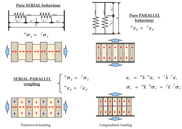
The classical mixing theory, based on the hypothesis that the strain tensor is exactly the same for all the composite components, is strictly valid only if it is applied to material components working in parallel. These materials are characterized by the fact that their stress state is the results of the sum of the stresses of each component, which are weighted proportionally to their volume in each phase with respect to the total. In order to solve this problem there are two alternatives: to define another closure equation (Equation (12)), suitable for the material phenomena simulation, or to carry out a modification of each one of the component’s properties and keep the strain equality hypothesis in each one of the composite components. Therefore, the main problem of classical mixing theory is the poor ability to represent the serial behavior of the components in the composite (Figure 6, iso-stress case).
5.2 Serial/Parallel mixing theory for one layer
Due to the classic mixing theory limitation, various modifications have been proposed (see [32]). These allow representing the composite component’s behavior participating in a combination of serial-parallel behaviors. This involves an automatic adjustment of the composite properties taking into consideration each component’s topology and distribution. Thus, each point of a solid can have a different strain.
Here, a short presentation of the serial/parallel mixing theory is made [1,27,39]. This rule of mixtures improves the classical mixing theory by modifying its closure equation, replacing the iso-strain hypothesis for an iso-strain condition in the fiber direction and an iso-stress condition in the transversal one (Equation (21)). The modeling of all the components distribution in the composite are shown in Figure 6. This formulation is an alternative to the homogenization technique, based on the multiple scale study [3,4,47,48,51].
The Serial/Parallel (SP) formulation [1,27,39] considers that the component materials of the composite act in parallel along a certain direction and in serial in the remaining directions. The main hypothesis in which the numerical model of the Serial/Parallel mixing theory are based on:
- 1. The composite is composed by two component materials: fiber and matrix.
- 2. The component materials have the same strain in parallel (fiber) direction.
- 3. The component materials have the same stress in the serial direction.
- 4. The composite material response is in direct relation with the volume fractions of the compounding materials.
- 5. The homogeneous distribution of phases is considered in the composite.
- 6. Perfect bounding between components is assumed.
Consequently, it is necessary to define and separate the serial and parallel components of the strain and stress tensors. Defining as the director vector that determines the parallel behavior in the fiber direction, the parallel projector tensor can be defined as
Using , the 4th-order parallel projector tensor , and the complementary serial projector tensor , are defined as:
|
|
(20) |
Both tensors are used to find the parallel and serial part of the strain tensor and respectively,
|
(21) |
Hence, the strain and stress tensors are split into its parallel and serial parts
|
|
(22) |
The equations that define the stress equilibrium and establish the strain compatibility between components are obtained from the analysis of the model hypothesis. Thus,
|
(23) |
|
(24) |
where, and are the parallel and serial components of the stress tensor respectively, and are the parallel and serial components of the strain superscripts, , and denote the composite, matrix and fiber materials, and and are the volumetric participation of fiber and matrix in the composite, respectively.
The serial/parallel mixing theory can use any constitutive equation to describe the behavior of each component material. The constitutive equations chosen can be different for each component (for example, an elastic law to describe the fiber behavior and a damage formulation to describe the matrix behavior). The constitutive equations for the matrix and the fiber can be expressed in the following form:
|
(25) |
where is the stress tensor of the component material, is the total strain tensors, is the respective damaged secant constitutive tensor and its elements are: ; ; ; .
The schematic S/P (or Generalized) Mixing Theory flow diagram of a numerical implementation, is shown in Figure 7.
5.3 Serial/Parallel mixing theory for a stacking layers composites
Laminate composites are formed by different layers with different fiber orientations. The orientation of the fiber can be defined by the engineer or automatically by an optimization process in order to obtain the better performance of the composite according to its application. The S/P- Rule of Mixtures formulation can be applied to each layer of the composite and, afterwards, the composite behavior is computed by combining the performance of each constituent layer. The classical mixing theory is applied to each layer to obtain the composite laminate behavior.
Applying the classical mixing theory onto the different layers of the laminate composite implies the assumption that all laminate are undergoing the same strain. This is a simplified approach, as the performance of a laminate in the direction perpendicular to the layers is in serial. However, as it is stated in Ref. [27], the loss of accuracy is minimal compared to the improvement in the computational effort. This is because the different layers of the laminate usually have fiber orientation distributions disposed in such a way that provide the laminate with an in-plane homogeneous stiffness, and loads are rarely applied perpendicular to the laminate.
5.4 Additional formulations used by S/P mixing theory to simulate reinforcement composite materials
Having defined the main frame of the formulation to deals with composite materials, there are other special formulations considered to obtain a better performance of the numerical simulation and approximation of the mechanical behavior of composite material structures. In this section, a brief description of them is considered.
5.4.1 Anisotropy using a mapping space theory
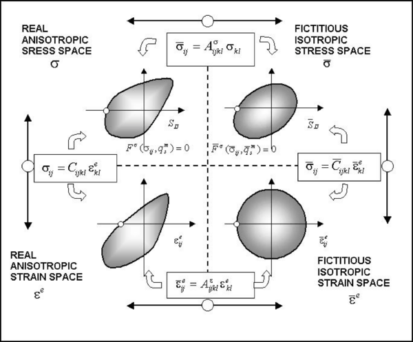
The mapping space theory permits take into account the anisotropy of each single component material [6,31,39]. It is based on the transportation of all the constitutive parameters and the stress and strain states of the structure, from a real anisotropic space, to a fictitious isotropic space. Once all variables are in the fictitious isotropic space, an isotropic constitutive model to obtain the new structure behavior can be used. This theory allows considering materials with high anisotropy, such as single or composite materials, using all the techniques and procedures already developed for isotropic materials.
All the anisotropy information is contained in two fourth order tensors. One of them, , relates the stresses in the fictitious isotropic space ( ) with the stresses in the real anisotropic space ( ) and the other one, , does the same with the strains. The relation of both spaces for the strains and the stresses is exposed in Equation (26).
|
|
(26) |
Once the stresses and strains are transferred to the respective isotropic spaces, the proposed constitutive equation is integrated, and its results are back to the anisotropic (real) spaces by a simple transportation operator ( ) (Equation (26)).
In Figure 8 a representation of these transformations is displayed. A more detailed description of this methodology, the extension to large strains and its numerical implementation can be followed in references [8,31,39].
5.4.2 Fiber-matrix debonding (FDM)
Matrix Reinforced Composite materials have a complex nonlinear behavior due to the reinforcement displacement because of the loss of adherence between the matrix and the reinforcement. This relative movement between the reinforcement and the matrix causes a loss of stiffness in the whole set and a decrease of the composite mechanical parameters without fractures in the reinforcement phase is observed.
The formulation introduced in previous section is based on the mechanics of the continuum medium to deal with the anisotropy and the mixing theory. It involves introducing an irrecoverable inelastic behavior in the constitutive equation to represent an approximation of the relative rigid movement of the body produced between the fiber and the matrix. The incorporation of the FDM into the constitutive equation must take into consideration two main characteristics: a) the global loss of stiffness due to the decrease of the fiber collaboration in the matrix and b) the irrecoverable relative displacement between the fiber and the matrix.
The fiber reinforced composite materials subjected to tension do not satisfy the kinematic condition imposed by the basic theory of basic substances. A direct consequence of this phenomenon is the matrix limitation to transfer the stresses to the fiber. In other words, the fiber cannot increase its tensional state as a result of the limited adherence in the fiber-matrix interface zone.
The Fiber-matrix debonding constitutive model is based on the assumption that the loading transfer from the matrix to the fiber varies when the matrix is under plastic strains [6,8,31,39]. The relative movement between the fiber and the matrix can be represented by the mechanics of the continuum medium through an irrecoverable inelastic strain in the fiber. The starting point of this phenomenon is determined through a threshold condition of maximum strength, which compares the effective stress on a point with respect to the fiber strength. That is, the fiber participation in the composite depends on its own strength and on the stress transfer capacity of the fiber-matrix interface. Therefore, its strength is influenced by the medium containing it and its constitutive treatment might involve a non-local formulation. Then, the fiber strength contained in a matrix is defined as:
|
|
(27) |
in which represents the radius of the long fiber of the transversal section, is the new fiber strength, is the nominal fiber strength, is the matrix nominal strength and is the fiber-matrix interface nominal strength. Equation (27) shows that the debonding happens when one of the composite constituents reaches its nominal strength (considering the fiber-matrix interface as a constituent). The numerical implementation of this phenomenon is described in the reference [6,8,39].
5.4.3 Tangent constitutive stiffness tensor
Depending on the constitutive equation used in a composite constituent material, the tangent constitutive tensor cannot be analytically obtained. One solution is to use, in these materials, the initial stiffness matrix, which will lead to the equilibrium state but will require a large amount of structural iterations. Thus, in order to obtain a fast and reliable algorithm, the expression of the tangent constitutive tensor is required. To obtain it, when no analytical expression exists, a numerical derivation using a perturbation method is performed [29,39]. The definition of the tangent constitutive tensor is:
|
|
(28) |
where,
|
|
(29) |
The definition of the tangent constitutive tensor, Equation (28), shows that the variation of stresses due to an increment in the value of the element of depends on the values of the column of . Thus, writing the column of as,
|
|
(30) |
the stress variation is:
|
|
(31) |
being the unknown.
The perturbation method consists of applying a small perturbation on to the strain vector and, using the constitutive equation of the material, determines the variation that will be obtained in the stress tensor due to this perturbation. At this point, the column of the tangent constitutive tensor can be computed as:
|
|
(32) |
For the smaller applied value to the perturbation, the better approximation is obtained for the tangent constitutive tensor. Having defined a perturbation value , the perturbed stress is computed using the constitutive equation of the material applying the following input strain:
|
|
(33) |
And the stress variation due to the perturbation is obtained subtracting the original converged stress from the computed one:
|
(34) |
This procedure must be repeated for all strain components in order to obtain the complete expression of the tangent constitutive tensor. Hence, the numerical cost of using a perturbation method is rather high. However, this procedure allows obtaining an accurate approximation to this tensor for any constitutive equation used, ensuring the Newton-Raphson convergence of the numerical process in few steps.
5.5 Local plastic-damage model for a component material
The theory of plasticity provides a suitable physical-mathematical framework to formulate the behavior of metallic materials subjected to loading. From the extension of its main basic principles and the reinterpretation of its main variables, the Plastic Damage Model has emerged as one of the more general plastic constitutive model [36,37,40]. This plastic model is based on the plastic damage variable formulated as an internal variable representing a unit normalized dissipated plastic energy ranging from . For there is no plastic damage and for the limit of total plastic damage in a solid point is defined. The latter state can be interpreted as a total loss of strength in a point of the solid produced for the accumulated plastic effect. A brief presentation of this model will be given in this section. For further details, check references [36,37,40]
In short, for a plastic mechanical process with no stiffness degradation, the plastic damage model uses the following set of plastic internal variables , and its evolution laws will be presented as part of the main equations governing the model.
- A deformation splits into an elastic and a plastic part,
|
|
(35) |
where is the constitutive elastic tensor.
- A plastic yield and potential plastic criteria are defined by the following two equations,
|
|
(36) | |
|
|
(37) |
being the plastic damage threshold function, the plastic potential, the cohesion or uniaxial strength evolution, depending on internal plastic damage variable , and are two scalar functions of tensorial arguments called yield function and plastic potential respectively, and can be represented by any classical limit criteria (von Mises, Mohr Coulomb, Drucker Prager, etc.) [26,34,40]
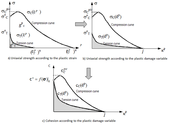
The uniaxial strength evolution is assumed as a scaled magnitude regarding an ultimate strength to uniaxial compression of the composite (stress discontinuity threshold), that is the stress level for which the volumetric deformation reaches its maximum value. Therefore, the initial uniaxial strength, is defined as for , setting the initial position of the yield criterion and the final uniaxial strength of the material totally deteriorated as, for , defining the final position of the yield criterion (see Figure 9).
Unlike the classic plasticity formulation with isotropic hardening, the cohesion or uniaxial strength in this case is not a simple function of the plastic hardening variable , but is an internal variable that depends on the evolution of the elasto-plastic process governed by its evolution equation.
- A plastic strain, plastic damage, and cohesion internal variables,
|
|
(38) |
all of them defined by the following evolution equations,
|
|
(39) |
where and ![]() are a second-degree tensor and a scalar function respectively that will be defined later, and which depend on the current state of the free variable and the rest of the internal variables . As observed in this equation, the main internal variable is the plastic deformation , and the others are obtained from it. The plastic consistency factor
are a second-degree tensor and a scalar function respectively that will be defined later, and which depend on the current state of the free variable and the rest of the internal variables . As observed in this equation, the main internal variable is the plastic deformation , and the others are obtained from it. The plastic consistency factor ![]() is obtained from the consistency condition of the plastic yield function [36,37,40].
is obtained from the consistency condition of the plastic yield function [36,37,40].
- A secant and tangent constitutive equation, defined as the classic plasticity,
|
|
(40) |
where is the kinematic plastic flow orientation [40]
The constitutive model resulting from these basic definitions shows a very good response during the general behavior composite process. To sum up, the model has the following characteristics:
- It defines a constitutive law depending on the internal variables of cohesion and plastic damage to represent non-radial complex loading situations.
- It deals with complex states of multiaxial stress in a unified way.
- It admits that materials have different limits of maximum strength and ultimate deformation, depending on the mechanical process in progress.
- It admits different plastic yield and potential criterion. Although this is not a characteristic of the model, it can be pre-established as one of its variables.
:* It can obtain all the information related to the point deterioration through the point mechanical information post processing.
5.5.1 Definition of the plastic damage variable
The classical plasticity theory establishes a hardening variable as a function of the effective plastic strain , or also as a function of the specific plastic work [34,35,40]. These definitions are suitable for materials whose final deformation is equal in tension as in compression as metal behavior. However, this assumption is not true for many materials as composites one. Therefore, it is necessary to establish an internal variable defining a unit-normalized dissipation, which is the relation between the density of the dissipated energy at a specific time of the process and the maximum dissipation of the point of the solid. Hence, it is said that the plastic damage variable is a unit-normalized measure of the dissipated energy during the plastic process.
Generally, for a generic loading process, the plastic damage variable is defined for a multiaxial mechanical process as,
|
|
(41) |
where is a second-degree tensor that, for uniaxial tension and compression processes, leads to a plastic damage depending on the loading process. To recover the plastic hardening variable of the classic plasticity theory, this tensor becomes equal to the stress tensor and in the general case it can be defined as a normalized dissipation to the unit for isotropic materials.
|
|
(42) |
where is the plastic dissipation energy, and are the fracture and crushing energy per unit of volume respectively, and are the mechanical fracture and crushing energy parameter, is a regularization parameter called characteristic length related with the finite element size, is a scalar function defining the tension-compression behavior states in each point as a function of the stress state, and ![]() is the Macaulay bracket. Note the following particular cases, for pure tension problems, for pure compression and for a pure shear state. Consequently, the plastic dissipation will always be normalized with respect to the maximum energy of the process at every moment.
is the Macaulay bracket. Note the following particular cases, for pure tension problems, for pure compression and for a pure shear state. Consequently, the plastic dissipation will always be normalized with respect to the maximum energy of the process at every moment.
Thus, the plastic damage variable is objective and evolves within the same limits regardless of the mechanical process. Thus, the total plastic damage in a point is reached when , but the dissipated energy will be ![]() in a pure tension process, and
in a pure tension process, and ![]() in a pure compression process.
in a pure compression process.
5.5.2 Definition of the cohesion or uniaxial strength evolution law
This plastic damage model assumes that micro-plastic damage in most materials is due to the loss of strength. Due to this failure mechanism, a softening in the strain-stress behavior can only be observed as a macroscopic effect (phenomenological model) caused by the average behavior of a set of points.
The plastic damage constitutive model carries out the numerical analysis on a finite domain (integration point of the constitutive equation) through the finite element functional approximation technique. Therefore, every point under analysis represents infinite material points contained in its area of influence. Thus, at macroscopic level, the softening phenomenon by deformation can be considered as a material property and, in such a case, a plastic hardening function must be defined taking into account this phenomenon. This hardening function is represented by the cohesion, written as an internal variable to make it more general and its evolution equation for any quasi-static loading process is defined as,
|
|
(43) |
where is a scalar function of the current state of the stress-free variable and of the internal variables and . The expression used for the evolution law of the internal variable of cohesion, or uniaxial strength, is obtained from the following expression for ,
|
|
(44) |
where is the aforementioned function which sets the type of behavior (tension or compression or tension-compression), developed during the mechanical process in each point of a solid. The cohesion function [13,40] is obtained in explicit form and it represents the cohesion evolution during a uniaxial simple compression test. The relation between cohesion and uniaxial stress of compression is given by the following expression,
|
|
(45) |
such that is a coefficient depending on the criterion of the discontinuity threshold and represents a scalar factor between cohesion and the uniaxial stress of compression [36,37,40]. For example, for Tresca and von-Mises its value is , for Mohr Coulomb where is the relation between compression-tension uniaxial strengths, for Drucker-Prager inscribed in the surface of Mohr-Coulomb and for Drucker-Prager circumscribed in the surface of Mohr-Coulomb . Thus, for any discontinuity threshold criterion, this coefficient must be defined.
The function (see Figure 9) can be obtained explicitly and represents the cohesion evolution during a uniaxial simple tension test. The relation between cohesion and uniaxial tension stress is given by the following expression,
|
|
(46) |
For Tresca and von-Mises its value is , for Mohr Coulomb , for Drucker-Prager inscribed in the Mohr-Coulomb surface and for Drucker-Prager circumscribed in the Mohr-Coulomb surface .
Some materials strength curves in simple tension and compression, obtained in uniaxial experimental tests, have similar shapes, in other words, it can be stated that the scale relationship between them is a constant during the whole quasi-static process and is given by
|
|
(47) |
In such case the explicit functions of uniaxial tension and compression cohesion coincide.
5.6 Local damage (elastic degradation) model for a component material
The local damage constitutive model [28,36,40] used to set the threshold for the initiation of non-linear elastic modulus degradation process in each point of component material of the composite one and its subsequent evolution is presented in this subsection. This concept allows the new definition of a global homogenized threshold criterion of damage for the entire laminate, resulting from the composition of the local damage index over all involved material in the laminate composite.
Material degradation -or damage- in a simple continuum material component due to a dissipative process can be simulated by means a local damage formulation [16,36,37,40,49]. This model is used at each simple matrix material embedded in the composite, inducing a stiffness degradation and strength reduction in the entire laminate.
The isotropic damage formulation is based on a scalar internal variable that represents the level of elastic degradation at each simple component material. This variable is bounded between 0 and 1, being zero for an undamaged and one for a completely damaged state of a single component material. The local damage variable is used to link the real stress tensor with the effective undamaged stress tensor . Therefore, the relation between the damaged stress and the strain in the matrix component included in each layer depends on the internal damage variable and the elastic constitutive tensor ,
| (48) |
In the same form of the plastic formulation, the stress condition at which damage starts and the evolution of the damage variable can be described by the following threshold function:
| (49) |
being the damage threshold function, the scalar equivalent stress function and the uniaxial strength evolution depending of the internal damage variable .
In the same form of the plastic damage model, this formulation allows the damage onset and evolution using any isotropic limit criteria already defined in literature (von Mises, Mohr Coulomb, Drucker Prager, etc.) [26,48], and the anisotropic behavior is included by means the mapping spaces theory previously defined in section 5.4.
The norm of the principal stresses with a different degradation path for tension and compression loads is also here defined for the widest range of structures in composite materials. That is,
| (50) |
being and the uniaxial ultimate strength of the material in compression and tension, respectively, the principal stress tensor, and is the same a scalar function defined in the plastic damage model, that take into account the tension-compression behavior states in each point as a function of the stress state,
| (51) |
and is the Macaulay bracket already defined.
The mechanical evolution of the damage inner variable or damage index for a simple component material is obtained by means the damage consistency equation [40] and the Kuhn–Tucker load/unload conditions [28,48]. The uniaxial strength function is defined as,
| (52) |
The function defines the softening evolution of the material. The behavior evolution of the damage material in the present work uses an explicit exponential softening, which is defined as,
|
|
(53) |
where is a parameter that depends of the fracture energy of each simple material. This parameter can be obtained for an exponential softening material as
|
|
(54) |
being the uniaxial Young modulus of the material, the damage compression energy of the material and the geometrically regularization parameter, called characteristic fracture length related with the characteristically size of the finite element used. The introduction of this fracture length in the formulation makes the degradation process mesh independent [28,48].
5.7 Global composite homogenized laminate damage index
In this section, the global damage index [38] to ensure that the composite laminate is found within the elastic range is defined.
According to the Serial/Parallel mixing theory previously introduced, fibers only collaborate to the composite strengthening in longitudinal direction of the fibers. Thus, the damage on the composite material is mainly concentrated in the matrix but not in the reinforcement fibers. Thereby, when stress in matrix reach its maximum elastic value (damage threshold), the material component falls according to the “damage constitutive law” or “plastic damage constitutive low” previously presented. At this time, the energy fracture dissipation begins in each component, and the material point cannot support any more the stresses level, the stiffness contribution disappears, and starts a crack evolution producing a delamination phenomenon. In addition, the lack of strength in the matrix in all directions is produced, except in the longitudinal fibers (because fibers do not reach the damaged threshold). Hence, this mechanism induces localized fracture (delamination) at constitutive level without the computational cost of breaking the mesh and re-meshing the new delaminated area.
In the case of laminates, the global composite damage index is obtained by the homogenization of de local damage variable or of each simple component materials (see previous sections). This definition of homogenized laminar damage can also be understood as a safety laminate output warning. This new structural damage index is also bounded between 0 and 1 as local damage variable and it is defined as,
|
|
(55) |
where are the local damage for a plastic or degradation process, and are the local damage variable and its Gauss point volume for each single material, is the number of Gauss points involved in all materials included in the layers participating in the finite element.
The safety laminate factor can be used, for instance, in optimization process to obtain the composite material design that accomplishes with the structural and functional design parameters [38].
The delamination phenomenon stops when a damaged point can provide enough shear strength to equilibrate the shear stresses that appears in the inter-laminar zone.
A potentiality application of this structural composite formulation, including a Water Current Turbine (WCT) rotor are introduced in next section.
6 “Micromodel” vs. “mixing theory”: Conceptual comparative behavior example
First, a simple and conceptual example intent shows the capabilities of the formulation here presented. Here a little sample of a fiber reinforced matrix is introduced, and shows the capacities of the “mixing theory with anisotropy in large strains” comparing the results obtained with a micromodel where each of the component materials is individualized.
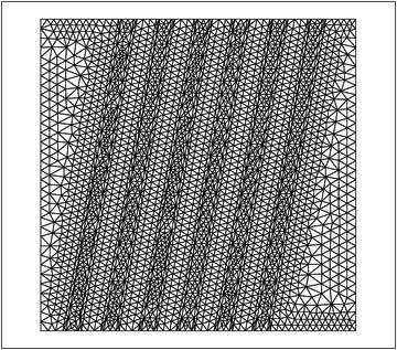
The example consists in subjecting a unit size cube of a composite material under tension in which the reinforcement fiber and matrix component are discretized. Then the results obtained by this micromodel are compared to the results obtained by the macro module proposed work. In Figure 10 the unit size piece is shown, where both phases of the composite material have been discretized. The boundary conditions imposed can also be observed. The finite element mesh is set up by 5701 triangular finite elements of 3 nodes and 2940 nodes.
As an alternative to the mesh described before for the numerical simulation through the model previously described, the same unit size piece modeled by only one single finite element of 4 nodes and 2 x 2 points of integration is analyzed. The sliding phenomenon between the fiber and matrix - Fiber-matrix debonding (FDM)-, will not be considered in this example.
The mechanical properties of the materials making up the composite are shown in Table 1, and Table 2.
| Isotropic Young modulus | 13,00 MPa |
| Poisson coefficient | 0,325 |
| Yield or threshold stress | 43,323 MPa |
| Damage-Plastic Post-yield behavior law | Exponential with softening |
| Fracture energy | 10 N/m |
| Volume participation Vm | 76% |
Table.1 – Epoxy resin properties for the macromodel and micromodel.
| Axial fiber Young modulus | 239,551 MPa |
| Transversal fiber Young modulus (*) | 13,00 MPa |
| Poisson coefficient | 0,0 |
| Yield or threshold stress | 3000 MPa |
| Damage Post-yield behavior law | Linear with hardening |
| Volume participation Vf | 24% |
(*)Note: Adopted equal to matrix elastic modulus
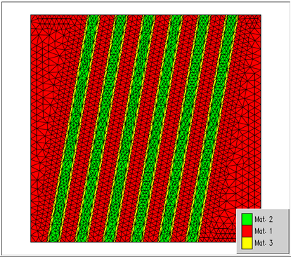
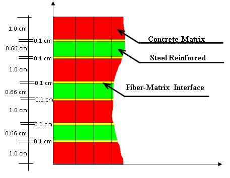
The micromodel is made up of three materials: reinforced fiber, epoxy matrix and fiber-matrix interface. Epoxy matrix and interface material are considered isotropic and homogenous and have mechanical properties that coincide with the mechanical properties of the macromodel components. In Figure 11 the micromodel materials distribution are shown schematically.
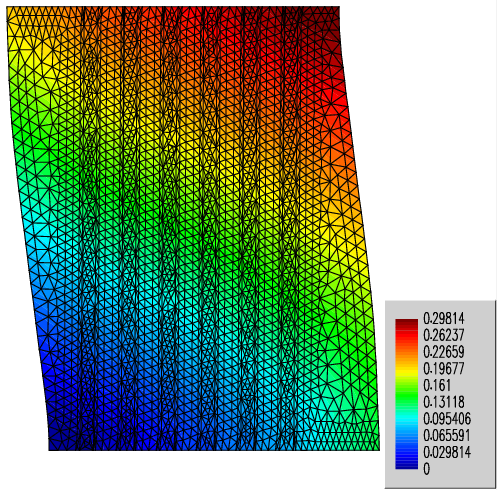
The numerical test consists in imposing displacements on the upper part of the unit size structure producing tension. This stress state on the specimen leads to the fiber reinforcement alignment with the load direction. In Figure 12 the deformed shape in its final state is shown. It can also be observed that the fibers have aligned themselves with the direction of the applied stress. This alignment of the reinforcement phase with the stress direction makes it necessary to introduce the theory of large strains in the constitutive model.
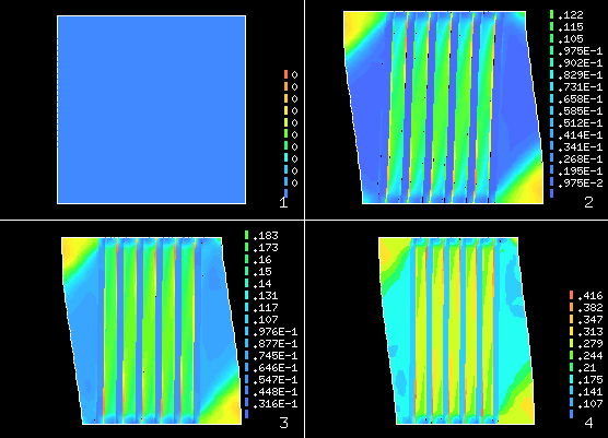
The advantage of using a micromodel is that a detailed analysis of the mechanical processes can be done during the load application. Figure 13 shows the shear stress on the material for different loading cases. Figure13-1 shows the stress states in a loading phase in which the stresses above the elastic limits of the component materials are not verified (see the plasticity internal variable in Figure 13). It can also be observed in the same figure that the matrix zone among the fibers is the one presenting a higher tensional state. As the displacements increase (Figure 13-2, Figure 13-3 and Figure 13-4) a homogenization of the matrix stress state is observed.
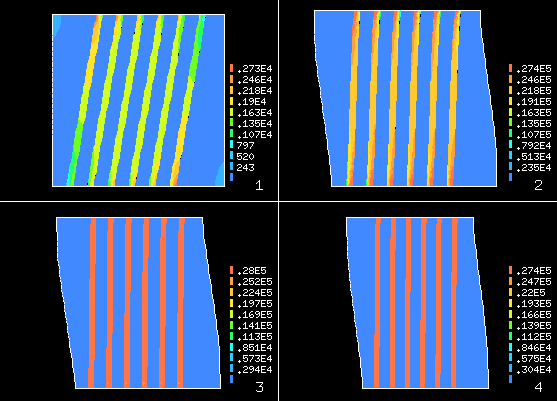
Figure 14 shows the stresses in the micromodel in the direction of the imposed displacements. Figure 14-1 corresponds to a stress state in a loading step in which the composite materials stresses above the elastic limit are not verified (see Figure 15). Figure 14-2, Figure 14-3 and Figure 14-4 show the stress state in the direction of the imposed displacement as displacements increase. It can also be observed that in the first loading steps the matrix has a homogenous stress state in the direction of the applied stresses. Figure 14-2 shows that the reinforcement increases considerably as it aligns itself with the direction of the stress applied.
Figure 14 shows the plasticity contours in each composite component. It also shows that as the displacement increases, the irreversible strains in the matrix are verified in the areas between reinforcements (see Figure 14-2 and Figure 14-3). In Figure 14-4 it can be observed that the elastic limit has been exceeded, consequently leading to irreversible strains.
.
Figure 16 shows the micro and macro models loading-displacement response. Different values of the transversal module of the reinforcement phase are considered. The same figure shows that the value of the transversal elastic module of this phase plays a fundamental role in the macromodel response. When the shear modulus is zero, it is observed that the matrix reaches its limit of proportionality while the tension in the composite decreases until the fibers coincide with the direction of applied stress. Beyond this point, the reinforcement phase provides stiffness to the system. The response corresponding to the small strains assumption can also be observed. In this case, once the matrix’s elastic limit is achieved, the material response decreases and the fibers do not participate in the response. This is because according to the small strain hypothesis the geometry is not updated and consequently the fibers cannot align themselves with the applied stress direction.
7 “Micro model” vs. “mixing theory”: Conceptual “Fiber Matrix Displacement” (debonding) behavior example
This example show a simple validation and comparison between the fibers sliding effect into matrix by means a "an isotropic mixing constitutive model formulation" and an "explicit finite element micro model".
An example of the formulation application combining the mixing theory, the anisotropic model in large strains and the theory that includes the FMD phenomenon analysis (Fiber-Matrix Displacement) is described below. This example compares the numerical simulation of the composite material specimen (reinforced concrete) with a central notch subjected to traction where the reinforced and matrix phases have been discretized (micro model), with a similar specimen in which only a composite material made up by a reinforced phase and the matrix (macro model) exists.
The numerical simulations have been carried out using a linear rectangular finite element mesh of 4 nodes with a total of 343 elements, 392 nodes and 766 degrees of freedom for the micro model and 291 elements, 336 nodes and 644 degrees of freedom for the macro model. Figure 17 shows the geometry, material assignment, meshes and boundary conditions used for each case.
| Material 1 Matrix of the
Concrete |
Material 2
Steel Reinforcement |
Material 3
Matrix-Reinforcement Interface | |
| Type of material behavior | Mohr-Coulomb
Isotropic Elasto-plastic Model |
Isotropic Elastic
Model |
Kachanov Damage
Model |
| Young Modulus [kp/cm2] | 3,5×10⁵
|
2,1×10⁶
|
3,5×10⁵
|
| Poisson Coefficient | 0,2 | 0,0 | 0,0 |
| Internal Friction | 30º | - | 30º |
| Compression Strength [kp/cm2] | 200 | 2000 | 20 |
| Tension Strength [kp/cm2] | 20 | 2000 | 20 |
| Gf , Gc [kp/cm] | 0,25 , 26,0 |
* |
2,0 , 2,0 |
| Behavior law after the
Yield point |
Line function
with softening |
* |
Exponential function
with softening |
The micro model consists of three materials: matrix, fiber-matrix interface zone and reinforcement. The macro model is made up of one composite material consisting of three component materials: reinforced fiber, matrix, and fiber-matrix interface. Table 3 shows the mechanical properties of the materials used in the micro model. The mechanical properties of the composite material phases in the macro model are identical to the corresponding ones in the matrix and reinforcement of the micro model.
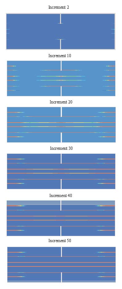
The purpose of this example is to show the loading transfer phenomenon from the matrix to the reinforcement phase. This is achieved first by comparing the “load-displacement” curve obtained by the micro model and then by the macro model made up of composite material, the components of which are not possible to identify physically (mixing theory) Figures 18 and 21 show the shear stress evolution in the fiber-matrix interface zone for different loading increments. The change of sign of the stresses, which are mainly due to the presence of the notch, can be observed in the central zone. Figure 20 and 21 show the longitudinal stress evolution in the reinforcement phase for different loading increments. It can be observed that for the first loading increment the maximum shear stresses are obtained at the reinforcement end zone, while the longitudinal stresses increase from zero at the end zone to a constant value along the reinforcement. Moreover, a variation of the longitudinal stress in the central zone due to the presence of the notch is observed. Additionally, a decrease of the stress transfer capacity from the matrix to the fibers is observed. This phenomenon also causes a modification of the stress state and, as observed, the stress distribution curve along the reinforcement is no longer constant. Figure 22 shows the interface zones exceeding the material proportionality limit for different loading stages. It can be noted that the fiber-matrix relative sliding starts at the fiber’s end zone and moves towards the specimen’s center.
.
Figure 23 shows the displacement contours in the first and final converged loading increments for the micro and macro models. As observed, in this last increment the displacements are basically in the specimen’s central zone and along the central reinforcement. A displacement is observed between the fiber and the reinforcement at the specimen’s ends.
Figure 24 shows the total forces’ response for micro and macro models. It can be noted that the micro model’s results match satisfactorily those of the macro model. It is important to highlight that the micro model cannot carry out the simulation of the relative movements between different phases but it can carry out the reinforcement simulation. However, the characterization of the latter would involve a considerable high computational cost of analysis due to the carbon fibers small dimension.
8 Numerical simulation of a structural analysis of a “composite material rotor-hydrofoil” of a Water Current Turbine (WCT)
The constitutive model described in this chapter is used in the structural numerical simulation of the composite turbine rotor. Reduction of rotational inertia of the WCT rotor is one of the principal aims of the fiber reinforced composite material application to this kind of structure. This will lower resistance to rotation in front of the river speed changes, allowing more flexibility in starting and stopping of the turbine rotation.
The numerical simulation of the multilayered composite structure design of the flow axial turbine rotor by means of finite elements method is presented in this section. A comparative study considering the structural response of the steel turbine rotor vs. fibers-reinforced composite material is carried out [38]. The composite material analysis is developed employing the orthotropic mixing theory previously presented, while an isotropic constitutive model is used for the steel rotor.
Geometry, boundary conditions and finite element mesh
The rotor is placed under an axial water flow described in section 3 that causes a distribution of pressures on the hydrofoils. These flow pressures are obtained by CFD finite element code and, particularly, in the leading edge of the hydrofoils of the rotor. The 8 rotor blades have a hydrodynamic profile with 15º of attack angle (see Figures 2, 3 and Table 4).
| 0.175 | 0.35 | 0.525 | 0.7 | 0.875 | 1.05 | 1.225 | 1.4 | 1.575 | 1.75 | |
| 0.182 | 0.145 | 0.128 | 0.116 | 0.108 | 0.102 | 0.104 | 0.093 | 0.089 | 0.086 | |
| 63.40 | 52.23 | 45.99 | 38.84 | 32.83 | 27.81 | 23.59 | 19.52 | 17.04 | 14.59 | |
| 16.23 | 15.61 | 15.2 | 14.89 | 14.65 | 14.46 | 14.33 | 14.79 | 14.17 | 14.05 |
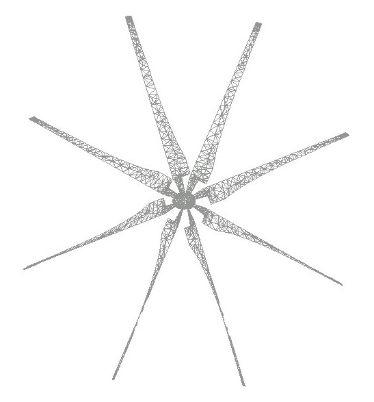
From the geometry of the rotor a mesh of 4100 linear shell triangular finite elements is generated (rotational-free shell triangle, [22]), with 2012 nodes (Figure 25).
These shells structure are analyzed firstly made of steel material and then made of laminate composites material with layers of epoxy matrix reinforced by unidirectional carbon fibers. In both cases, the properties of the materials are detailed in tables 4 and 5.
Action on the hydrofoil’s rotor
The water pressures obtained by the Section 3 formulation on the blade of the turbine rotor in the axial axis are applied. These pressures are obtained from CFD code for the fluvial flow at low speed river (see section 3) [15,29]. This pressures cause two kinds of loads in the rotor:
- Load 1: Rotation loads on the surfaces of the hydrofoils produced by the differential pressures between the up and down surfaces of the wing. This load is obtained by the CFD finite element code (Computational Fluid Dynamics) to obtain the speed, correct attack angle of hydrofoils, diagrams of pressures on the wing areas, etc.
- Load 2: Axial loads caused by the directly applied pressures over the attack edge of the hydrofoil, that cause its deformation and the tensional state of the rotor, trending to break it in the perpendicular direction of the plane of the rotor. This reaction forces are studied and analyzed in this example through the previously composite-formulation included in a structural finite element program (Figure 26).
Kinematic pressures are obtained by CFD finite element procedure which is available on the reference Oller et al. [15,29]. Thus, using this pressure has been obtained an applied load of
at the leading edges surfaces of the hydrofoils. This load is distributed over all nodes of the blades, and is applied in one time step, in the rotor at time  . A more complete fluid dynamic numerical simulation using the section 2 a 3 formulation can be found in reference [15,29].
The restrictions of movement are applied to the nodes corresponding to the turbine shaft, representing the sharing points between the rotor and the axis of the turbine.
Numerical simulations of the rotor made of steel and composite material.
The details of the structural behavior of each rotor conformed in steel and composite laminate are described below. In the structural analysis of the composite laminate, the previously general formulation is used. An additional parametric comparison is also carried out in this case chosen from three pairs of fiber directions and stacking sequences.
Numerical simulations involves the turbine steel rotor with the following mechanical parameters: density , Young modulus , Poisson ratio , and thickness ; and the turbine rotor made by composite six layers, each one with thickness, and three different composite layups: , 0º-90º and 0º-45º, (see mechanical properties of components in Table 5), are used in the analysis comparison.
It can be observed after the 1s applied load, that the minimum stress, (Table 6 and Figure 26b), corresponds to the non-orthogonal 0º-45º layup configuration, which occurs in the blades near to the shaft junction.
| Composite | |
| Matrix | |
| 60% of volume fraction | |
| Fiber
reinforcement |
|
| Type of rotor | T [mm] | Required Starting torque [Nm] | Maximum stress [Pa] | Maximum displacement [m] |
| Steel | 1.8 | 217 | 25.324,00 | 2,21E-03 |
| Comp. ±45º | 6×0.3=1.8 | 40 | 13.397,00 | 1,65E-03 |
| Comp. 0º/45º | 6×0.3=1.8 | 40 | 10.622,00 | 2,73E-03 |
| Comp. 0º/90º | 6×0.3=1.8 | 40 | 12.342,00 | 2,42E-03 |
Figure 26b and 26d shows that the "0º/45º” laminate composite rotor works with nearly 40% level of stresses of the steel rotor. The "±45º" composite laminate rotor and the "0º/90º" composite laminate also work at less stresses than steel rotor (Table 6).
All composite laminate rotors have less stiffness than the steel rotor, but particularly the composite with fibers oriented to "±45º has a high stiffness and near to the steel value (see its relative comparison, Figure 26d). However, the composite laminate of "0º/45º” has a much lower stiffness than the other (Figure 26d), but is enough for this machine requirements, as its maximum displacement is tolerable in these work functions (see its relative comparison, Figure 26c).
The reduced starting torque of composite laminate rotor is a big advantage during the operating work of the water turbine, since composites have 5.5 times less starting torque than the steel rotor (Figure 26a). It means a machine with better performances at low water flux velocities, easier to ship, handle, repair, start, etc.
Concluding, the composite laminated rotor of fibers oriented to "±45º" is the best suited material for this function, since it has a very low rotational inertia (18.3% of the steel rotor. See Figure 26a), a maximum working stress a 47% lower than the steel rotor (Figure 26b), and finally has a good stiffness (53% of the value corresponding to the steel rotor. (see Figure 26d)
9 Conclusions
Riverbed hydroelectric development is a concept that is currently being successfully explored by several researchers, and the use of composite materials in the design of these turbines adds a significant technical and economic improvement over the use of classical materials as shown in this work.
This book chapter’s presents a numerical formulation for the design and analysis of composite material structures to be used within the energy sector of renewable energies.
The numerical formulation is based on the Serial/Parallel mixing theory as manager of the different constituent models for the composite material components. Also the local damage constitutive model is employed to set the threshold for the initiation of non-linear damage process (initiation damage) in each point of the composite material. These concepts allow a threshold criterion of damage resulting from the composition of the behaviors of all material involved in the theory of mixtures. The homogenization of local damages obtained in each one of the composite constituents to measure the damage in a shell structure is also presented.
Taking advantage of the composite materials compared to the classic ones, a very good performance of the Water Current Turbines (WCT) immersed in the rivers is obtained, improving its performance thanks to its smaller rotational inertia.
The numerical model for the treatment of the Composites of Water Current Turbines (WCT), and its fluid dynamics, shows a way forward and establishes a work base that offers an important tool for the design and analysis of these turbines.
10 Future works
Two research sub-lines are proposed below to future research in the electric-power exploitation using hydrokinetic turbines.
A) From the turbine point of view and its location in each particular place, the research progress is currently made on fluid-dynamic design to optimize the rotor and the rest of the machine. In this order of things are proposed new devices and infrastructures of hydraulic flow control, which will allow a speed increase at the entrance to the turbine to improve the electrical performance. Another aspect that is also being studied is the design of sanders and separation of material in suspension to avoid impact of objects on the rotor. All this type of studies is related to the particular behavior of each kind of river.
B) From the point of view of the composite material constituting the turbine, the central theme of this chapter, future research is aimed at obtaining new fabric-reinforced compounds, which are more resistant, rigid and appropriate to withstand impacts, than compounds Reinforced with unidirectional fibers. To this end, the formulation of the S / P Theory of Mixtures presented here is currently being reformulated and generalized to fit these new materials. This, along with the great deformations and the incorporation of the misalignment of the fibers of the fabric, will allow to properly considering the interaction between orthogonal fibers located in the same plane, bases for the numerical simulation of the fabrics-reinforced composites.
11 Nomenclature
A Swept area
Design attack angle (º)
Real angle of attack (º)
Maximum aerodynamic profile’s (º)
β Hydrofoil’s camber angle (º)
Airfoil chord (m)
Relative flow velocity
Lift coefficient
Drag coefficient
VC2 dimensions
Ratio between and
Chord average
Airfoil’s chord for each (m)
Pressure (Pa)
Gravity acceleration ( )
Fluid density ( )
Radius of the rotor
Shape factor
Shape factor for each
Torque (Nm)
Time (s)
θ Hydrofoil’s sustentation angle (º)
Blade linear rotational speed (m/s)
Absolute flow velocity (m/s)
: Ratio between and
Power (w)
Angular speed (rad/s)
Length of each hydrofoil segment (m)
Wingspan (m)
Number of blades of the rotor
Load (N)
Young modulus ()
Poisson ratio
Tension strength (
)
e Thickness (m)
Material strain
Plastic material strain
i-Component material strain
Volumetric deformation
Volumetric participation coefficient of the component
Free energy of the component
Composite material stress ()
i-Component material stress ()
i-Secant and i-Tangent Constitutive tensors
Serial and Parallel strains
Serial and Parallel stresses ()
4th-order parallel projector tensor
4th-order complementary serial projector tensor
4th-order stress mapping tensor
4th-order strain mapping tensor
Isotropic fictitious stress ()
Isotropic fictitious strain
Kinematic plastic flow orientation
Plastic dissipation energy
Fiber strength ()
Nominal fiber strength ()
Nominal matrix strength ()
Nominal fiber-matrix strength ()
Plastic and Damage thresholds
Group of the Plastic and Damage internal variables
Plastic potential
Function of the damage strength softening evolution
Damage compression energy of the material
Plastic and Damage internal variables
Structural damage index
12 References
[1] F. Rastellini, S. Oller, O. Salomón, E. Oñate, Composite material non-linear modelling for long fibre-reinforced laminates. Continuum basis, computational aspects and validations. Computers and Structures 86 (2008) 879-896.
[2] X. Martinez, S. Oller, E. Barbero, Study of delamination in composites by using the serial/parallel mixing theory and a damage formulation, Composites 2007, U. Porto. 12th to 14th Septemer/2007.
[3] E.S. Sánchez-Palencia, Boundary layers and edge effects in composites, in E. Sánchez Palencia, A. Zaoui (Eds), Homogenization Techniques for Composite Media, Springer-Verlag, Berlin, 1987, 121-192.
[4] S. Oller, J. Miquel, F. Zalamea, Composite material behavior using a homogenization double scale method, Journal of Engineering Mechanics131 (2005) 65-79.
[5] F. Otero, S. Oller, X. Martinez, O. Salomón, Numerical homogenization for composite materials analysis. Comparison with other micro mechanical formulations. Composite Structures 122 (2015) 405-416.
[6] S. Oller, E. Car, J. Lubliner, Definition of a general implicit orthotropic yield criterion. Computer Methods, Applied Mechanics and Engineering 192 (2003) 895-912.
[7] C. Trusdell, R. Toupin, The classical field theories, Handbuch der physic, iii/I ed., Springer-Verlag, Berlin,1960.
[8] E. Car, S. Oller, E. Oñate, An anisotropic elasto-plastic constitutive model for large strain analysis of fiber reinforced composite materials, Computer Methods in Applied Mechanics and Engineering 185 (2000) 245-277.
[9] F. Otero, X. Martinez, S. Oller, O. Salomón, An efficient multi-scale method for non-linear analysis of composite structures, Composite Structures 131 (2015) 707-719.
[10] L.I. Lago, F.L. Ponta, L. Chen, Advances and trends in hydrokinetic turbine systems. Energy for Sustainable Development 14 (2010) 287–296.
[11] S. Ben Elghali, M. Benbouzid, J. Charpentier, Marine tidal current electric power generation technology: state of the art and current status, IEEE International Electric Machines & Drives Conference 2 (2007) IEMDC'07.
[12] M.A.R. Shafei, D.K. Ibrahim, A.M. Ali, M.A.A. Younes, E.A. El-Zahab, Novel approach for hydrokinetic turbine applications, Energy for Sustainable Development 27 (2015) 120–126.
[13] M. Khan, M.M Iqbal, J. Quaicoe, River current energy conversion systems: Progress, prospects and challenges, Renewable and Sustainable Energy Reviews 12 (2008) 2177–2193.
[14] M. Khan, G. Bhuyan, M. Iqbal, J. Quaicoe, Hydrokinetic energy conversion systems and assessment of horizontal and vertical axis turbines for river and tidal applications: A technology status review, Applied Energy 86 (2009) 1823-1835.
[15] S.A. Oller Aramayo, L.G. Nallim, S. Oller, Fluid dynamic design of an axial rotor for hydrokinetic riverbed turbine-improvement introduced by a high lift foil profile, Environmental Progress & Sustainable Energy 35 (2016) 1198–1206.
[16] M.S. Selig, J.J. Guglielmo, High-Lift Low Reynolds Number Airfoil Design, Journal of aircraft 34 (1997) 72-79.
[17] S.A. Oller Aramayo, L.G. Nallim, S. Oller, The usability of the Selig S1223 profile airfoil as a high lift hydrofoil for hydrokinetic application, Journal of Applied Fluid Mechanics 9 (2016) 537-542.
[18] J.N. Goundar, M. Rafiuddin Ahmed, Y. Lee, Numerical and experimental studies on hydrofoils for marine current turbines, Renewable Energy 42 (2012) 173-179.
[19] A. Betz, Introduction to the Theory of Flow Machines, Pergamon Press, Oxford, New York, 1966.
[20] W. Froude, On the elementary relation between pitch, slip and propulsive efficiency, Transactions of the Royal Institute of Naval Architects (1878).
[21] J.S. Carlton, Marine propellers and propulsion,2th ed., Elsevier, Oxford, 2012.
[22] T. Hughes, Multiscale phenomena, Green’s functions, the Dirichletto-Neumann formulation, subgrid-scale models, bubbles and the origin of stabilized methods, Computer Methods in Applied Mechanics and Engineering 127 (1995) 387–401.
[23] J. Guermond, Stabilization of Galerkin approximations of transport equations by subgrid modeling, M2AN 33 (1999) 1293–1316.
[24] M. van Tooren, Response 1 - Airbus composite aircraft fuselages – next or never, in: C. Vermeeren (Ed), Around Glare a New Aircraft Material in Context, Springer, Netherlands, 2007, pp. 145-158.
[25] J. Ferziger, M. Perić. Computational methods for fluid dynamics, Springer-Verlag, Berlin Heidelberg, New York, 2002.
[26] O.C. Zienkiewicz, L.R. Taylor. The finite element method, McGraw-Hill, London, England, 1991.
[27] X. Martinez, F. Rastellini, F. Flores, S. Oller, E. Oñate, Computationally optimized formulation for the simulation of Composite materials and delamination failures, Composites Part B: Engineering Part B 42 (2011) 134–144.
[28] J. Oliver, M. Cervera, S. Oller, J. Lubliner, A Simple Damage Model For Concrete, Including Long Term Effects, Second International Conference on Computer Aided Analysis and Design of Concrete Structures, Viena, 2 (1990) 945-958.
[29] X. Martinez, S. Oller, F. Rastellini, A. Barbat, A numerical procedure simulating RC structures reinforced with FRP using the serial/parallel mixing theory, Computers and Structures 86 (2008) 1604 – 1618.
[30] X. Martinez, S. Oller, Numerical Simulation of Matrix Reinforced Composite Materials Subjected to Compression Loads, Arch Comput Methods 16 (2009) 357-397.
[31] E. Car, S. Oller, E. Oñate, A Large Strain Plasticity for Anisotropic Materials – Composite Material Application, International Journal of Plasticity 17 (2001) 1437-1463.
[32] S. Oller, E. Oñate, A Hygro-Thermo-Mechanical constitutive model for multiphase composite materials, Int J Solids and Structures 33 (1996) 3179-3186.
[33] J. Lubliner, Thermomechanics of Deformable Bodies. Department of Civil Engineering, University of California, Lecture Notes, Berkeley, U.S.A, 1985.
[34] J. Lubliner, Plasticity theory. MacMillan, New York, 1990.
[35] G.A. Maugin, The thermomechanics of plasticity and fracture, University Press, Cambridge, 1992.
[36] J. Lubliner, J. Oliver, S. Oller, E. Oñate, A plastic-damage model for concrete, International Journal of Solids and Structures 25 (1989) 299 - 326.
[37] S. Oller, E. Oñate, J. Oliver, J. Lubliner, Finite element non-linear analysis of concrete structures using a plastic-damage model, Engineering Fracture Mechanics 35 (1990) 219-231.
[38] S.A. Oller Aramayo, L.G. Nallim, S. Oller, An Integrated procedure for the structural design of a composite rotor-hydrofoil of a water current turbine (WTC), Applied Composite Materials 20 (2013) 1273-1288.
[39] S. Oller, Numerical Simulation of Mechanical Behavior of Composite Materials. CIMNE-Springer, Barcelona, Spain, 2014. ISBN 978-3-319-04932-8.
[40] S. Oller, Nonlinear dynamics of structures. CIMNE-Springer, Barcelona, Spain, 2014. ISBN 978-3-319-05193-2.
[41] J. A. Paredes, A H. Barbat and S. Oller, A compression-tension concrete damage model, applied to a wind turbine reinforced concrete tower. Engineering Structures 33 (2011), pp. 3559-3569. ISSN: 0141-0296. DOI information: 10.1016/j.engstruct.2011.07.020.
[42] E. Comellas, S. Ivvan Valdez, S. Oller, S. Botello, Optimization method for the determination of material parameters in damaged composite structures. Composite Structures 122 (2015), pp. 417–424. ISSN: 0263-8223, doi:10.1016/j.compstruct.2014.12.014.
[43] F. Otero, X. Martínez, S. Oller, O. Salomón, Study and prediction of the mechanical performance of a nanotube-reinforced composite. Composite Structures. Vol. 94, pp.2920–2930. 2012. ISSN: 0263-8223
[44] R. F. Rango, L. G. Nallim, S. Oller, Static and dynamic analysis of thick laminated plates using enriched macroelements. Composite Structures, Volume 101, 2013, Pages 94–103. ISSN: 0263-8223.
[45] M.A. Pérez, X. Martínez, S. Oller, L. Gil, F. Rastellini, F. Flores, Impact damage prediction in carbon fiber-reinforced laminated composite using the matrix-reinforced mixing theory. Composite Structures. Volume 104, issue, year 2013, pp. 239 - 248. ISSN: 0263-8223.
[46] R. F. Rango, L. G. Nallim, S. Oller, An Enriched Macro Finite Element for the Static Analysis of Thick General Quadrilateral Laminated Composite Plates. Mechanics of Advanced Materials and Structures (2015). ISSN 1537-6494 (Print), 1537-6532 (Online). DOI: 10.1080/15376494.2015.1068400
[47] M. Petracca, L. Pelà, R. Rossi, S. Oller, G. Camata. E. Spacone, Regularization of first order computational homogenization for multiscale analysis of masonry structures. Computational Mechanics, 57(2), 257-276, (2016). DOI 10.1007/s00466-015-1230-6. Print ISSN: 178-7675, Online ISSN: 0178-7675.
[48] F. Otero, X. Martínez, S. Oller, O. Salomón, An efficient multi-scale method for non-linear analysis of composite structures. Composite Structures, Volume 131, Pages 707-719. 2015. ISSN: 0263-8223, doi:10.1016/j.compstruct.2015.06.006.
[49] J. Paredes, S. Oller, A. Barbat (2016). New Tension-Compression Damage Model for Complex Analysis of Concrete Structures. Journal of Engineering Mechanics – ASCE. 04016072. Jun./2016. ISSN: 0733-9399. doi: 10.1061/(ASCE)EM.1943-7889.0001130
[50] C. Escudero, S. Oller, X. Martinez, A. Barbat, A laminated structural finite element for the behavior of large non-linear reinforced concrete structures. Finite Elements in Analysis and Design. Vol. 119, 15 October 2016, pp 78–94. ISSN: 0168-874X. doi:10.1016/j.finel.2016.06.001
[51] M. Petracca, L. Pela, R. Rossi, S. Oller, G. Camata, E. Spacone, Multiscale computational first order homogenization of thick shells for the analysis of out-of-plane loaded masonry walls. Computer Methods in Applied Mechanics and Engineering. 315 (2017), pp 273–301. ISSN: 0045-7825. DOI: http://dx.doi.org/10.1016/j.cma.2016.10.046.
[52] A. Botto, P. Claps, D. Ganora, F. Laio, Regional-scale assessment of energy potential from hydrokinetic turbines used in irrigation channels. 4th International Conference on sustainability & Environmental Protection (SEEP2010) Conference Proceedings, June 29th–July 2nd, Bari, Italy, 2010.
[53] M. Anyi, B. Kirke, Review: Evaluation of small axial flow hydrokinetic turbines for remote communities. Energy for Sustainable Development. Volume 14, Issue 2, June 2010, Pages 110–116.
[54] K. A. R. Ismail, T. P. Batalha. A comparative study on river hydrokinetic turbines blade profile. Int. Journal of Engineering Research and Applications, Vol. 5, Issue 5, (Part 1) May 2015, pp.01-10.
[55] N. Kolekar, Z. Hu, A. Banerjee, X. Du, Hydrodynamic Design and Optimization of Hydro‐kinetic Turbines using a Robust Design Method. Proceedings of the 1st Marine Energy Technology Symposium METS13 April 10‐11, 2013, Washington, D.C.
Document information
Published on 01/01/2017
Licence: CC BY-NC-SA license
Share this document
Keywords
claim authorship
Are you one of the authors of this document?

