Sustainable Pedestrian Bridge using Advanced Materials (SUPERBAM)
| Lara Pellegrini
Civil Engineer |
Ramon Ribó
PhD Civil Enginneer |
Javier Jordan
MSc Civil Eng., ICCP, PE,Peng PEDELTA jjordan@pedelta.com |
Juan Sobrino
PhD. Civil Eng, ICCP,
|
Summary
Fiber-reinforced polymer pedestrian bridges are becoming a competitive alternative to conventional concrete or steel pedestrian bridges in the span range from 5 to 30 m. In order to consider it as a viable alternative, it is necessary, among other things, to be price competitive in the total cost of the bridge, including construction and full-life maintenance. One of the ways of making the cost competitive is to normalize a few cross-sections and create a catalog of standard cross-sections and shapes depending on the load conditions and ranges of spans. The objective of this work has been to create this catalog, taking into account the following items: A detailed economic analysis of the impact of every sub cost in the total construction and maintenance cost. A detailed structural analysis and optimization, by using MEF, of different cross-section and laminate solutions has been carried out, both under static and dynamic loads, in order to achieve the best possible design. The preparation of a specialized FEM analysis software that already includes in its database the chosen laminates as well as automatized geometrical construction and standarised load cases definition. With all these tools, it is possible to make highly reusable molds for the laminates and it is possible to make the final cost of the FRP pedestrian bridge more competitive.
Keywords: advanced materials; laminates; GFRP; aesthetics; structural concepts; new materials
1. Introduction
The development and improvement of sustainable mobility around the world is urging the construction of pedestrian bridges in urban, as well as rural and remote, locations. Meanwhile, developed countries in Europe and around the world are coping with the aging of existing transportation infrastructures. A significant number of bridges require periodic maintenance and some major repairing or replacement to safely fulfill their functions.
Construction of public infrastructures has a great impact on sustainability and the use of advanced materials, such as Fiber Reinforced Polymers (FRP) and Stainless-Steel (SS), contributes to sustainable development. The idea of using high-strength, lightweight, and reusable materials that require minimum maintenance and accelerate construction is the goal of this research.
Most existing pedestrian bridges are trusses made with pultruded standard profiles. There is a technical limit to using these components, due to the fabrication process, and aesthetics are usually poor. The connections are typically bolted and their design is one of the most critical elements. Adhesive connections can also be used in combination with bolts.
There is a need for developing new structural concepts using FRP or hybrid structures. SUPERBAM research project has developed specific geometries and structural concepts to take full advantage of advanced materials (high strength, lightweight, durable, and sustainable) using modular systems and providing attractive appearance.
2. Objective of the research
The specific objectives of the SUPERBAM research project are the following:
- 1) Develop a catalog of standard modular footbridges made with advanced materials to cover small and medium spans (spans ranging from 10 to 30 m). The structures will be designed to be assembled using light modular members/profiles. Focus will be concentrated on the connections between members that should be reliable and easy to build.
- 2) The new concept will be based on the idea that railings should work as a part of the structure to optimize the use of the materials with a high initial cost.
- 3) The bridges should have a minimum amount of connections (modular construction).
- 4) Aesthetics and possibility of tailor-made structures is also key in making the bridges attractive.
- 5) Develop specific structural analysis techniques for the general design of the structure.
- 6) Develop specific structural analysis software for the detailing design with particular attention to the connections (one of the critical points of the structure).
- 7) Develop a reliable pre-engineered catalog of sustainable pedestrian bridges using advanced materials.
3. Technological steps and how they have been addressed
Specific FRP or hybrid structural types and concepts for pedestrian bridges, not repeating the same solutions valid for concrete or steel structures. This conceptual design includes the design of a modular construction structural system, the analysis of the dynamic behavior of very light structures to mitigate vibration and the design of connections and methods of assembly.
A feasibility study of deployable/foldable structures has been done to know the possibility to obtain a structure with the ability to change its geometry from a compact configuration (easy to be stored and transported) to a functional shape. A deployable structure requires active elements during installation.
Validation of new concepts using specific numerical software or adapting advanced numerical codes validated in other industries (aerospace, naval industry).
Analysis of manufacturing process to select the most appropriate materials (GFRP, CFRP, SS, hybrid structures), fabrication process (pultrusion, vacuum infusion, hand lay-out, etc.), and structural shapes.
4. Fabrication technique
4.1 Mold
The main structure has a U-shaped form and profiles will be constructed using separate molds. The molds should allow for the creation of various identical sections with minimal effort. They must be cost effective and reusable, and thus continued experimentation is being done.
Molds are typically constructed using a model. To start, a prototype of the section is developed and refined to eliminate any imperfections. Successive layers of fabrics pre-impregnated with liquid resin are then placed to create an inverted self-supporting structure (the mold). Both single-use molds and permanent molds exist. A male mold acts as the interior of the structure with the product fabricated around the mold. A female mold contains the structure, acting as the structure’s exterior.
4.2 External laminate
The mold surface is stabilized at high temperature and undergoes a vacuum integrity test. A release agent is applied on the stabilized mold surface. This is then typically followed by a thick layer of gelcoat, which is intended to provide a uniform finish with a desired color. Liquid resin is then applied and on top of it the first layer of reinforcing fabric is placed. Rollers are used to apply pressure over the fibers to infuse and deaerate the layer. These steps are repeated, applying layers of fabric and resin until the desired thickness is reached and ensuring that the layers fit perfectly to the complex shape of the mold. Vinylester is used as a type of mat and is placed between each thin layer of fabric in order to absorb the resin and obtain the thickness. An evolution in the structural design and resin matrices has allowed for a reduction in the use of the mat and a substantial increase in direct fiber proportion in the laminate. This reduces the number of layers necessary to obtain the determined strength and resistance.
4.3 Vacuum technique
The incorporation of vacuum techniques in traditional contact lamination has resulted in important advances in regards to physical and mechanical properties of pieces and structures made with composite materials. A soft, closed container shrinks or collapses if external pressure is increased, and the same effect occurs if the internal pressure is reduced. By enclosing the laminate in a sufficiently sturdy bag and removing the air within, a uniform pressure of approximately 1 atmosphere (101.325 KPa) can be obtained at any point, even if the form is complex in shape. The results obtained by vacuum lamination present significant advantages over traditional contact lamination. There is a reduction in thickness, air content and final weight, while a homogenous and uniform quality, free of imperfections, is achieved.
4.4 Sandwich infusion
The most basic and common process of all infusion techniques consists of first placing layers of fibers, the core and other inserts over the outer surface of the mold without the use of resin. This can be done slowly, ensuring a clean shape, which is an important factor that affects the final quality of the piece and entire project. Once this first step is complete, the vacuum bag and other items specific for infusion are placed over the group. Once the assembly is sealed, and with the help of the vacuum, the first compaction is carried out which assists in the stabilization of the piece and the increase of fiber content per volume while reducing voids. After reaching the desired level of compression, inlets are opened to saturate the piece with liquid resin while all of the air inside is expelled using the vacuum tubes.
4.5 Assembly and finishing
The various pieces that comprise the footbridge are put together with the help of mechanical unions and structural adhesives. The assembly will require a final finish, painting, polishing, supplement incorporation, etc. until the desired end result is achieved.
5. Software design
There are standard structural FEM analysis code that can be used to simulate and design a FRP bridge. However, they are quite generalist and very time consuming to prepare all the data for the analyses.It has been considered very important for this project to develop an specialized simulation package in order to facilitate the design of FRP bridges.
The RamSeries software package is a complete Finite Element (FEM) environment for structural analysis that includes a composite module with laminate sequences and plies direction, based on geometric lines orientations following local or global frames of reference with static and dynamic analysis and results verification, based on LaRC04 failure criteria, including six failure modes, and Tsai-Wu criteria.
In this new tool, the most recent algorithms and libraries involving graphical interfaces, data base communication and CAD geometry parametric creation have been included and/or developed. Furthermore, one of the main design objectives of the tool was to create a piece of software which would allow the user to obtain results quickly, with an automatic creation of the geometry and CAE model. Therefore, the user is just requested to insert a few geometrical design parameters and data related with normative loads. Also, sets of materials are pre-loaded as libraries, so the user can simply select them, saving the time of creating the lamination sequences for the composites.
5.1 Superbam FEM program
The bridge design tool developed for SUPERBAM project is an advanced Graphic User Interface, which allows a non-expert user to actually perform an optimization of the bridge design. The use of the tool makes it easy to define the geometry of the section, and automatically creates the 3D CAD bridge model.
It also automatically applies the boundary conditions, loads and material properties chosen by the user. Finally it generates the FEM mesh, calculates, and directly takes the user to the post-process view, where the different results can be visualized and extracted as a report, if needed.
The design guidelines are exposed below.
5.1.1 Bridge geometry definition
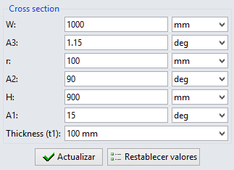
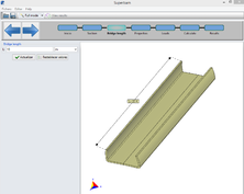
The bridge cross section has been designed to be structurally efficient, including structural handrails, while minimizing structural depth below walkway surface.The bridge cross-section and the span are defined parametrically. Up to seven different parameters can be modified in order to change the shape of the bridge cross-section. This section is to be extruded automatically up to the bridge length defined by the user.
|
|
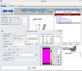
5.1.2 Materials definition
It is possible to assign different laminates to each different part of the bridge: Top, Floor, Lateral or Round laminates. The predefined materials can be modified, and new ones can also be created.
5.1.3 Loads definition
In addition to geometrical guidelines [1], codes also define loads, such as wind, live, and accidental loads, partial safety factors, and structural verifications requirements [2]. In the “Loads” section, the user can modify the different parameters which create the loads that are going to be automatically applied on the model. These loads can be static or dynamic. For static analysis, it is possible to define the full set of combined loadcases. For dynamic analysis, pedestrian loads are created. These loads have been implemented according to the theory in “Dynamic Behaviour of Footbridges Subjected to Pedestrian-Induced Vibrations” (Fjalar Hauksson, Lund University. ISSN 0281-6679) [3]. Additional verifications have been made in accordance with the technical guide “Footbridges, Assessment of vibrational behavior of footbridges under pedestrian loading”, SÉTRA, 2006 [4]
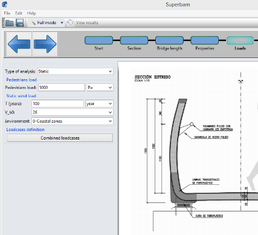
Fig. 3. User Interface loads definition |
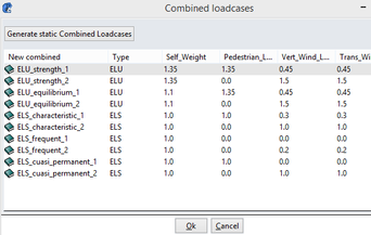
Fig. 4. Combined Loadcases |
7.4.4 Results
It is possible to visualize the deformed structure as well as several stress values like Tsai-Wu and the stresses tensor in top and bottom laminates as well as in any interior laminate. Extensive reports are automatically generated.
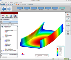
Fig. 5. Displacements |
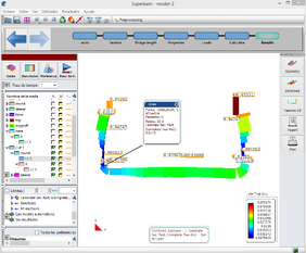
Fig. 6. Tsai-Wu criteria |
6. Prototype manufacturing
From the different possible options (inner/outer mold, inner only, or outer only), we have decided to implement the simplest, the inner only, and to set up an arrangement for single use; this also applied to the environmental control. Profiles are in MDF, reinforcements are pine strips, shaped panels are plywood planks, and top sides are plasticized OSB, treated with demolding wax.
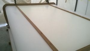
Fig. 7. Manufacturing step 1 |
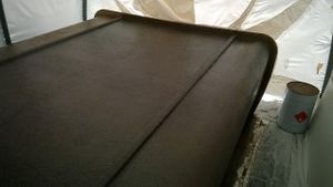
Fig. 8. Manufacturing step 2 |
For the manufacturing process, we chose the WET LAY-UP/HAND LAY-UP technique, where the resin is impregnated into the sheets of fibers by hand using metallic and soft rollers. The work is done at normal atmospheric conditions. In order to extend the working time until gelification and cure, we have used moderated amount of activator (1.25-1.75%) according to the ambient temperature. We sequenced the two types of fibers (Qaxial/CSMat) in six layers, each as per the specifications tables, overlapping the cloth over the bottom raised edge and always closing with mat to ensure that the intermediate sanding is done over the previous one.

Fig. 9. Manufacturing step 3 |
 Fig. 10. Manufacturing step 4 Fig. 10. Manufacturing step 4
|
The core selection includes two types of cross cut and one plain and is applied by layers, taking care to not overlap the cuts. The adhesive is fabricated by adding silica and chopped fibers to the resin of the basic laminate. The resultant filler may have more or less density according to the requirement, like filling the gaps, running between layers or if vertical or horizontal layering is intended.
The outer skin is laid up until the end in the lower section and in a series of steps in the sides in order to stabilize the whole piece before the turning over.
Cutting the edges immediately before the turning over. The front and the back sides have been closed by overlapping the inner and the outer skins, so double thickness is achieved. This will be convenient if assemblies by spigots or other mechanical junctions between bridges are envisaged.
Immediately after demolding. The inner skin has a glossy finish at the sides but there will be an anti-slip pattern in the middle (still hidden by a peel-ply). This walkway is flanged by the drainage channels.
7. Prototype testing
7.1 Loads tests
Some static and dynamic load tests have been performed in laboratory using a prototype created specially for this verification. Prototype dimensions are 2.37m (length) x 2.20 m (width) x 0.94m (height)
Fig. 11. Experimental tests
7.1.1 Static load test
The prototype is supported over two simple wood supports with a 2 m free span (L). Load is applied in the span center by using sand bags. Load is progressively increased in 200 kp steps from 0 kp to 1926 kp. Maximum measured deformation at midspan was 6mm. It is below its maximum admissible value, L/205.
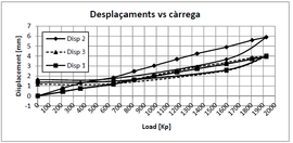
Fig. 12. Displacements vs Loads |
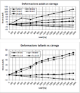
Fig. 13. Axial & shear deformation vs Loads |
7.1.2 Dynamic load test
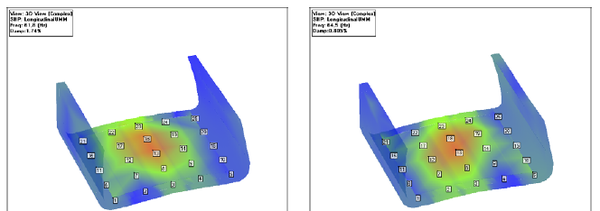
The objective of the test is to estimate the main dynamic parameters, including natural response frequencies, vibration modes, and damping for the prototype. To do so, a dynamic load is applied by using an instrumented hammer. Two analyses are performed. One in the horizontal plane and another in the vertical walls.
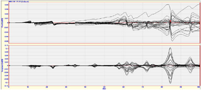
Fig. 14. Frequency response function horizontal |
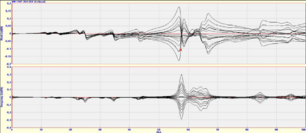
Fig. 15. Frequency response function vertical |
8. Conclusions
FRP pedestrian bridge design has been demonstrated as a very competing technology compared to traditional solutions [5], [6] when it is taken into acount the full bridge lifespan, including construction and maintenance costs. Moreover, these solutions are specially suitable when there are special needs, like remote transports, speed of construction and agressive environmental conditions.
The work developed in this research project has permitted to optimize the design and construction process and has developed some software tools that will facilitate future FRP pedestrian bridges designs. These tools are mainly a catalog of shapes, materials, and cross-sections based on load requirements and bridge spans and a software package that includes the parametric designs, the selection of predefined FRP composite laminates, with a sandwich type panel using a poliethylene core and external GFRP laminates, and the FEM analysis for static and dynamic verification of the structure.
9. Acknowledgement
The authors would like to acknowledge ACC1Ó (Generalitat de Catalunya) and ERDF (European Regional Development Fund) for the funding support for the research project. And to the companies COMSA, StyleCarbon and Compass Ingenieria y Sistemas for their contribution.
10. References
[1] fib: Guidelines for the Design of Footbridges. 2005
[2] Design Manual for Roads and Bridges. BC90/05. Design of FRP Bridges and Highway Structures. The Highways Agency. ISBN 0115526684. May 2005.
[3] Dynamic Behaviour of Footbridges Subjected to Pedestrian-Induced Vibrations. Fjalar Hauksson, Lund University. ISSN 0281-6679
[4] Technical guide “Footbridges, Assessment of vibrational behavior of footbridges under pedestrian loading”, SÉTRA, 2006.
[5] Sobrino, Juan A “Pedestrian bridges with hybrid Stainless Steel-GFRP structure” IBC-11-51
[6] Sobrino J. and Gomez M.D, “Towards advance composite material footbridges”, Structural Engineering
International, Nr 2, 2002, pp 84-86.
Document information
Published on 01/01/2017
Licence: CC BY-NC-SA license
