Algoritmo de remallado automático de elementos triangulares durante los análisis con elemento finito
A.R. Hermosillo, M.P. Romo, R. Magaña, J. Carrera
Instituto de Ingeniería, Departamento de Geotecnia
Universidad Nacional Autónoma de México. Coyoacán. México D.F.
Resumen
En este trabajo se presenta un algoritmo de refinamiento automático de elementos finitos triangulares. Es bien sabido que los tamaños de los elementos de la malla juegan un papel importante en el modelado de un medio continuo, particularmente cuando existen diferencias notables en las propiedades de los materiales en zonas contiguas del medio. En tales casos, la malla debe ser lo suficientemente fina en tales áreas con el fin de obtener resultados fiables. Por lo tanto, en este artículo se presenta un algoritmo para llevar a cabo el remallado automático de áreas locales donde se activa el refinamiento de la malla acordemente a los criterios de "remallado". Aquí el algoritmo propuesto, integrado en un programa de computadora de elementos finitos en dos dimensiones, se utiliza para analizar un problema clásico de geotecnia para mostrar la importancia de refinar localmente la malla y para demostrar que, independientemente de las características geométricas de la malla inicial, los resultados del algoritmo son prácticamente iguales. Los cálculos obtenidos con el método propuesto se comparan con la correspondiente solución cerrada del problema, para mostrar la utilidad y fiabilidad del algoritmo de remallado. Por otra parte, con el fin de mostrar la versatilidad del algoritmo, en los casos incluidos en este trabajo se alteran las condiciones de frontera (de carga) consideradas inicialmente con el fin de mostrar cómo el remallado automático local es capaz de adaptar la configuración inicial de la malla en una nueva como una función de las nuevas condiciones de frontera. Como se muestra en el documento, las mallas resultantes obtenidas para ambas condiciones de frontera son sensiblemente diferentes entre sí, lo que conduce a resultados diferentes.
Palabras Clave: Elemento finito, remallado automático, geotecnia, cimentación superficial flexible, análisis numérico
Automatic remeshing algorithm of triangular elements during finite element analyses
Abstract
In this paper an automatic remeshing algorithm of triangular finite elements is presented. It is well known that the element sizes of the mesh play an important role in modeling the continuum, particularly when notable material properties differences exist in contiguous areas of the medium. In such cases, the mesh must be fine enough in such areas in order to obtain reliable results. Therefore, in this paper is advanced an algorithm to carry out automatic remeshing of local areas where the “remeshing” criteria is activated to refine the mesh accordingly. Herein the proposed algorithm integrated into a two dimensional finite element computer program is used to analyze a classical geotechnical problem to show the importance of locally refining the mesh and to demonstrate that regardless of the geometric characteristics of the initial mesh, the algorithm yields practically equal results. Computations with the proposed method are compared with the corresponding close form solutions, whenever available, to show the usefulness and reliability of the remeshing algorithm. Furthermore, to show the algorithm’s versality, the initial loading boundary conditions considered for the cases included in this paper are modified in order to show how the automatic local remeshing is capable of adapting the initial mesh configuration into a new one as a function of the new boundary conditions. As shown in the paper, the final resulting meshes for both load boundary conditions considered are appreciably dissimilar from each other, which leads to somehow different results.
Keywords: Finite element, automatic remeshing, geotechnics, shallow strip foundation, numerical analysis
1 Introduction
The finite element method is a powerful, practical and versatile numerical analysis tool for solving differential equations through continuum discretization, but its efficiency and effectiveness can be notably hampered if local refinements during the analyses are made manually, which likely will lead to continuum discretization errors. As it is well known, finite element accuracy depends on how well the mesh mimics the continuum particularly where abrupt material properties originally exist or develop due to local material plastization of a number of fine elements. Likewise, the mesh has to be fine enough to accurately describe the problem geometry (i.e., soil-structure) and capture sharp changes in local stress and/or strain gradients stemming from the heterogeneity in material properties and abrupt changes in the problem geometric characteristic (i.e. soil-concrete interfaces of embedded foundations).
Finite element approximations improve either by reducing the size of finite elements (refining specific zones of the mesh by automatic remeshing) or increasing the order of the polynomial shape function. Of course, a combination of these two approaches may be set up. In the past, several approaches have been proposed to generate and refine locally the finite element mesh [1, 2]. Additionally, many mesh generation techniques have been automated, such as the Delaunay triangulation [3, 4], the advancing front approach [5], mesh generation using contours [6], the coring technique [7], the “quadtree” technique [8], etc., are available to generate gradation triangular meshes [9]. Moreover, a number of studies have been carried out for modelling contact regions [10], also to avoid large aspect ratios in order to maintain an adequate approximation level [11] and to compute accurate solutions when large mesh distortions develop during computations [12]. Furthermore, algorithms for refinement/derefinement of nested meshes using fractal concepts and iterated function systems (IFS) have been proposed [13, 14, 15, 16]. Evolution problems have been addressed elsewhere [17]. There, the mesh evolution with respect to the boundary conditions is addressed to. In addition, the skeleton based refinement (SBR) has been used to refine unstructured meshes for 2D and 3D problems [18]. At this stage, it is worth mentioning that in the method proposed herein the core triangle from which refining starts is divided using geometric fractal construction procedures that, to the authors´ knowledge, is innovative.
Broadly, a remeshing procedure is characterized by:
(i) A remeshing criterion related to either an error estimator of the calculation accuracy, or the local distortion mesh or the spatial discretization of the boundaries
(ii) A mesh generator assuming element size distribution inside the domain or around its boundaries depending on the chosen error estimator
(iii) A transfer procedure that carries out a mapping of history dependent variables from the old to the new mesh for each remeshing step.
It is important to mention that several criteria such as shear failure, strain rate, stress rate, gradient, etc., can be specified to trigger the remeshing procedure. Accordingly, the mesh refinement could be carried out automatically at different zones of the finite element mesh at the same time. It should be mention that the procedure advanced in this paper applies to both structured and unstructured triangular finite element meshes. Furthermore, the algorithm proposed herein can start from any rough finite element mesh, and after a few iterations the ad hoc (tailored) mesh for the problem at hand is settled, assuring that the results are accurate as shown in this paper through comparisons with the close form solution of a flexible shallow slab footing on a homogeneous half-space discretized with two different meshes.
It is a common practice to define the finite element mesh according to the initial boundary conditions of specific problems. However, in many actual cases the boundary conditions may be modified over the time (i.e., earthquakes, foundation vibration, circulating vehicles on roads, and so on) , or even the stress state can be altered due, for example, to soil consolidation due to overloading and/or water withdrawal from the underground aquifers. In spite of the likelihood of these possibilities, in practice usually the finite element mesh is defined for the initial conditions of the problem without repairing in the potential consequences. The algorithm proposed herein automatically carries local mesh refinement whenever initial load and/or boundary conditions, as well as stress-strain states are modified. To show the influence of loading boundary conditions, a horizontal load is added to the slab foundation above mentioned.
2 Automatic remeshing
In this chapter an automatic remeshing algorithm to locally refine finite element triangular meshes is introduced. Refining of particular zones of the mesh are carried out should the threshold criteria adopted is exceeded throughout the finite element computations.
To show the versality of the algorithm a very rough initial finite element mesh is defined throughout the foundation example, and then the refinement proceeds in the areas where the threshold criteria (more than one criterion can be assigned to each mesh element) are exceeded; localized refinements are performed iteratively until all finite elements fulfill the threshold conditions. Henceforth, the finite element computations will be more precise in the refined critical areas, and the overall results would be closer to those given by the close form solutions. Furthermore, with this algorithm through many successive iterations, it is possible to define failure mechanisms of specific geometrically complex problems [19]. This capability can be used to visualize the physics of very complex problems, and consequently improve modelling.
2.1 Remeshing algorithm
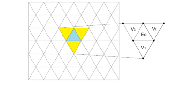
After establishing automatically the finite elements that must be refined to satisfy the threshold criteria, the stress-strain state in every finite element of the mesh is calculated and determined as to whether or not the remeshing criteria is still violated in any finite element of the mesh. This process is iterative and automatically stops when the adopted criteria are satisfied in every finite element integrating the mesh. The remeshing algorithm branded AFIRM is designed to refine triangular elements in particular local areas without altering the whole mesh as indicated in figures 1 and 2. The three basic steps for generating the finite element mesh to cover the remeshing zone are [20, 21]:
- 1. Node generation
- 2. Building links between nodes to form the elements, and
- 3. Use of density functions to properly redistribute the nodes and form regular meshes in the region where remeshing is needed
2.2 Procedure followed for triangular elements of three nodes
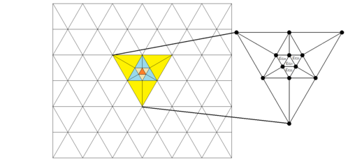
It is important to make it clear that local remeshing initiates from the triangle, where the threshold criterion is exceeded. This triangle is branded central element, Ec, which is defined by the points P1, P2 and P3 and propagates to the three adjacent triangles V1, V2 and V3, as indicated in figure 1. This is a key feature of the procedure proposed in this paper. The elements where the threshold criteria dictate that mesh refinement should be carried out are considered as the “central triangle Ec” from which the commented process proceeds. Then, the Ec triangle is broken into four elements ΔEc11 , ΔEc12 , ΔEc13 , ΔEc14 which implies that (ΔEC= ΔEc11 ΔEc12 ΔEc13 ΔEc14 forming a new upside down central triangle the vertices of which are the midpoints of the sides of the initial central triangle P7, P8 y P9 (see figure 2). This implies that, the three adjacent triangles V1, V2 and V3 be bisected, generating the six triangular elements (ΔV11, ΔV12, ΔV21, ΔV22, ΔV31, ΔV32) shown in the inset of figure 2. Note that three nodes and six triangular elements are added to the original (or previous) mesh for each element to be refined; the central element, Ec, is divided into four elements which are numbered from the central, Ec, and the adjacent V1, V2 and V3 elements of the original (or previous) mesh. Each of the adjacent elements to the three sides of the central element are bisected yielding new elements that are numbered sequentially starting from the maximum element number existing in the original (or previous) mesh. The new nodes are numbered following the same scheme as that adopted for element numbering. This procedure guaranties refinement be confined on the central and adjacent triangles. Accordingly, remeshing does not spreads farther away.
Hence, the original (or previous) set of four triangles becomes a set of 10 in one iteration, and in two iterations increases to a set of 16 (see figure 3). Once this stage is accomplished, finite element computations are carried out to determine if the threshold criteria (or criterion) in all finite elements (including the new elements) are fulfilled. This process is repeated every time the criteria for refining locally the mesh are not met. Although this method is very simple, the configuration of the grid after several (as many as desired) iterations will be “tailored” to the particular characteristics of the problem, leading to highly reliable results. It is fair to mention that most generating-finite element meshes experts would never even think in performing iterations to further refine the mesh they designed to assess the properness of their mesh-modelling.
The proposed remeshing algorithm sometimes leads to the formation of peripheral triangles with rather high aspect ratios. To overcome this shortcoming the two rules described below should be enforced:
Rule 1: If two elements are considered central and both share a common side, neither of the neighboring elements will be bisected and only inward refinement will be allowed.
Rule 2: If two central elements share any side with a third element, the third element is automatically considered central and refinement of the three elements must follow Rule 1 specified above.
To activate these two rules an evaluation of side ratio, SR, defined as SR= (Large Side / Short Side) of all generated triangular elements is carried out first. If, as a result of the refinement of a particular central element, an adjacent element has an SR bigger than the specified SRth threshold, this adjacent element is considered as a central element in further iterations. It is important to note that the software was designed in such a way that should the initial mesh contains highly distorted elements, the computer program will automatically reshape them to fit the SR requirement (see block diagram in figure 4).
Figures 2 and 3 show that this iterative process avoids the inclusion of invalid nodes in the remeshing procedure. The key feature of the proposed method is that it can be repeatedly applied to any element of the modified mesh at consecutive iterations, as depicted in figures 2 and 3. The block diagram in figure 4 shows how the process of automatic remeshing is coupled with finite element analyses. It is important to mention that this approach can be adapted to any regular or irregular region (structured and destructured meshes). Moreover, with slight modifications it can be applied to 3D thin membranes.
2.3 Block diagram
As indicated by the block diagram in figure 4, after eliminating from the finite element mesh all highly distorted elements, the procedure begins cycling according to the history of boundary conditions to be changed (i = 1 to N Bound Cond) so that a data file (block 1) containing information on the finite element mesh characteristics, boundary conditions, applied forces, material properties, etc., is integrated.
For each loading boundary condition a finite element stress-strain analysis is performed (block 2). After determining the stress-deformation state, a search for elements that do not fulfill the threshold criterion is carried out. Once these elements have been identified the refining process starts using the proposed remeshing algorithm (block 3). The threshold criterion that triggers the refining of the finite element mesh may be arbitrarily chosen by the user. For example, it may be defined in terms of a maximum allowed normal and/or shear stress; also a percentage of the shear strength defined by constitutive models such as the Critical State, Mohr Coulomb or any of the user’s preference. To make sure none of the triangular elements resulting from the remeshing have high aspect ratios, a review of the SR parameter values is performed in order identify triangular elements having large aspect ratios and proceed to apply the two rules mentioned above.
Once the elements to be refined have been determined, the remeshing algorithm is applied to produce a new finite element mesh (block 5). This step is repeated as needed or specified (from j = 1 to N Iterations), and at each iteration a stress-strain analysis of the refined mesh is performed. Once the remeshing process is complete, new boundary conditions are added according to the loading history and the whole process is repeated. Material properties can be modified accordingly in each iteration.
The remeshing process ends when there are no more changes in the load conditions and all the mesh triangles satisfy the threshold criteria. Because this algorithm is coded as an independent subroutine, it can be included in any other finite element software that uses triangular elements.
The finite element software that includes the remeshing algorithm used in this study can be obtained by direct request to the senior author.
3 Algorithm assessment
3.1 Initial mesh element distribution influence
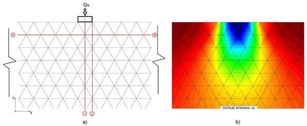
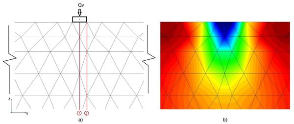
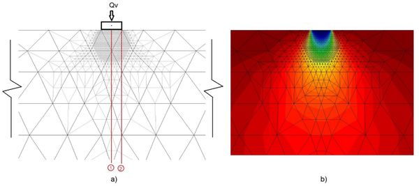
In order to show the potential, effectiveness and reliability of the fractal remeshing algorithm, the analytical solution for the flexible strip surficial foundation, used as example, is compared with the finite element solutions (in terms of vertical stresses along axes 1 and 2 indicated in figure 5a) obtained considering two initial different meshes. The main purpose of discretizing the medium using two different rough meshes was to assess the algorithm capabilities of refining the original meshes to such degree that accurate computations are reached, no matter what their initial configuration and roughness are. Accordingly, finite element analyses were carried out to evaluate the usefulness and the versatility of the proposed algorithm. The results obtained after four iterations of refining the original meshes yielded almost identical results, demonstrating that the algorithm is capable of reaching converging results regardless of the initial mesh configuration. Moreover, when compared with the analytical solution this conclusion is backed up.
In order to ensure that areas with singularities in the stress state are detected and refined accordingly, the threshold criteria used in the examples included herein, were chosen to be 50, 60, 70, 80 and 90% of the octahedral shear strength for the refinement iterations 1, 2, 3 and 4, respectively. Furthermore, the maximum triangular aspect ratio for both examples was defined to be 2.5.
Both problems are alike regarding the medium boundary conditions, unit loading on the foundations (Qv/(B*1)=qv=3000 kgf/m2 (29.42 kPa), where Qv is the vertical total external foundation load, B=1 m is the width of the slab and qv is the unitary load), and soil material properties (Young´s modulus=203943 kgf/m2 (1999 kPa) and a 0.49 Poisson´s ratio). The magnitude of the horizontal load added to modify the loading boundary condition was assumed equal to Qv.
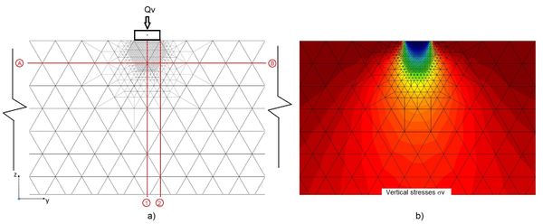
Mesh 1. Figure 5a depicts the original finite element of mesh 1, and Figure 5b shows the vertical stress bulbs defined from the results obtained from the finite element analyses using rough mesh 1. In figure 7a the finite element mesh obtained after four automatic iterations starting from the initial mesh 1 is depicted. For comparison purposes, the refined mesh is overlapped on to the original rough mesh. It can be seen that mesh 1 was refined in zones near the boundary where the load is applied, this concurs with the higher stress rates near the boundary loading. Far away from where the load is applied, the initial mesh is not modified. One advantage of the remeshing is that the size of the finite elements increase smoothly and their aspect ratio is kept smaller than 2.5, hence avoiding abrupt size transitions within the area where stress-strain rate variations are significant. Comparing figures 5b and 6b, becomes clear that the locally refined mesh is capable of bringing out with much more detail the stress bulbs than does mesh 1, particularly at the local zones where larger stress (strain) gradients are developed (i.e. near the loaded area): While the bulbs in figure 5b are rather blurry, those in figure 6b are clearly defined. It is convenient, at this point, to mention that the vertical and horizontal axes drawn in figures 5 and 6 are sections where some finite element results, computed using the rough and the 4-iteration refined meshes, are compared to highlight the importance of applying consecutively the automatic remeshing algorithm to preclude that critical zones be missed and hence more reliable results will be obtained.
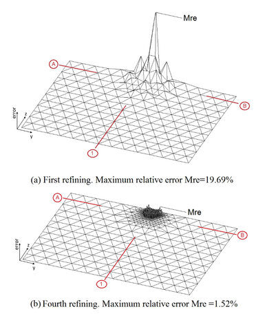
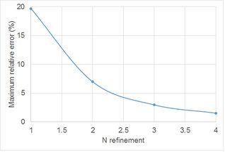
To stress further the importance of automatically refining some zones of the mesh, the plots in figure 7 show the spatial variation of the relative error of the nodal displacements from one iteration to the next. In this figure, for space limitations, are only shown the first and fourth refining iterations. The results show that from the original mesh to that resulting after one iteration, the maximum relative error was 19. 69%, this error dropped to 6.97% from the second to the third iteration and after four iterations the maximum relative error fell to 1.52%. The iteration-decreasing rate of the maximum relative errors plotted in figure 8 evidence the importance of mesh refining as computations go along for achieving safe and economic designs. The decreasing error rate in figure 8 indicates that as the number of iterations increase, the maximum relative error tends to zero (i.e., the analytical solution is reached [22]).
The comparison among the vertical stresses computed along axes 1 and 2 (shown in Figures 5 and 6) presented in Figure 9 shows the importance of adapting the mesh to the iteration-varying stress rate, particularly near the loading boundary or singular conditions that could be developed because of soil plastization at certain zones that require finer elements to better compute the actual stress-strain state. This figure also highlights the fact that the four-iteration refining finite element mesh results reproduce almost exactly the theoretical solution, contrary to those obtained when the original mesh is used. Of course, even closer approximations can be obtained defining more stringent thresholds.
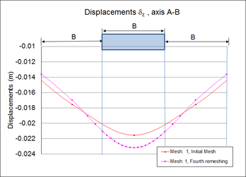
To assess the influence that local remeshing would have on the vertical displacements, they were computed along horizontal axis AB (see Figures 5 and 6), located down to 0.866 m from the ground surface. Figure 10 compares the vertical nodal displacements computed for both initial rough mesh 1 and those corresponding to the fourth-iteration refined mesh. The mesh-refining-effect is appreciable not only on the displacement magnitudes, but also on the width of the displacement gorge: as the mesh elements size decreases the vertical displacements increase (particularly beneath the strip foundation) and the displacements gorge becomes narrower.
Mesh 2. The main difference between mesh 1 and mesh 2 is that the latter includes distorted triangular elements. Figure 11a shows the initial finite element mesh 2, and Figure 11b depicts the vertical stress bulbs defined from the results obtained from the finite element analyses using the initial mesh 2. In Figure 12a the finite element mesh obtained after four automatic iterations starting from the initial rough mesh 2 is illustrated. For comparison purposes, the refined mesh is overlapped on to the original rough mesh 2. It can be seen that the original mesh 2 was refined in zones near the boundary where the load is applied, this concurs with the higher stress rates near the loading boundary than far removed from it, where the initial mesh is not modified. As shown before, the finite elements increase smoothly maintaining the shape ratio smaller than 2.5 hence avoiding abrupt size-shape transitions within the area where stress-strain rate variations are significant. Comparing Figures 11b and 12b becomes clear that the locally refined mesh is capable, as in the previous example with mesh 1, of bringing out with much more detail the stress bulbs than does the original rough mesh, particularly at the local zones where larger stress (strain) gradients are developed (i.e. near the loaded area): while the bulbs in Figure 12b are rather blurry, those in Figure 12b are clearly defined.
The comparison among vertical stresses computed along axes 1 and 2 (shown in Figures 11 and 12) presented in Figure 13 shows the importance of adapting the mesh to the iteration-varying stress state, particularly near the loading boundary or singular conditions that could be developed because of soil plastization at certain zones that require finer elements to better model the continuum and compute more accurate actual stress-strain states. This figure also highlights the fact that the four-iteration refining finite element mesh results reproduce almost exactly the theoretical solution for vertical stresses along axes 1 and 2, contrary to those obtained when the original mesh is used. Moreover, comparing the vertical stresses computed for mesh 1 and mesh 2 along axes 1 and 2 (Figures 9 and 13), it is seen that the proposed algorithm in this paper leads to the same results no matter what the initial geometry of the finite elements are.
These results suggest that the algorithm can also be used to ameliorate the elements shape of any triangular finite element mesh, specifying a shape ratio threshold. This was achieved by adding a block in the flow diagram included in Figure 4 that preforms the conditioning process of the triangles to the prescribed aspect ratio.
3.2 Boundary conditions influence
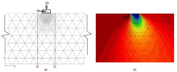
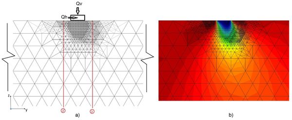
Nowadays most finite element analyzes of actual problems are carried out keeping unchanged the original mesh, regardless the potential load boundary conditions variation with time in real problems (i.e. rockfill dams, soil pore-water withdrawal, moving loads). It is worth mentioning that Ferragut and Plaza [17] recognized this shortcoming and studied this issue for heat time-variation throughout plates. Herein, to show the influence of modifying the load boundary conditions on the shear stresses, the loading condition of the slab on the ground surface example so far used in this paper was modified by adding a horizontal load, so the load boundary condition includes now vertical (existing) and horizontal (added) loading. In this simple example, the refined mesh obtained according to vertical loading only was refined again considering both vertical and horizontal loads (Figures 14 and 15). These figures show clearly that when using the refined mesh considering only vertical loading the foundation-rear stress bulbs that the horizontal load generates are not developed. Accordingly, it can be argued that the stress states would differ from each other. These results indicate that the finite element meshes should be modified according to the ongoing load boundary conditions.
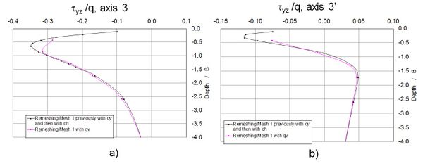
Figure 16 shows the normalized shear stresses yz along axes 3 and 3´. It is seen that the remeshing considering the present loading conditions has a significant effect from the ground surface down to a depth equal to the foundation width. Therefore, the results obtained in this paper seem to indicate that whenever the elements of the initial mesh are not modified as a function of the ongoing load conditions, the results could lead to biased conclusions regarding the problem under consideration. Hence, meshes defined for particular problem conditions are not generally suited for the same problem whenever the load boundary conditions are modified.
4 Conclusions
From the results presented in this paper the following conclusions can be drawn:
- 1. The use of the algorithm proposed in this paper for automatic refinement of finite element meshes allows to detect critical or unstable areas in the continuum such as shear bands (i.e. failure mechanisms) and the possible origin of cracks. Through the examples included in this article, it is shown that the procedure automatically applied as many times as required by the threshold criterion selected, leads to ad hoc (tailored) finite element meshes.
- 2. Based on the results presented in this paper, it is advised to carry out mesh refinement according to the ongoing load boundary conditions. The results of the simple examples included in this paper seem to indicate that there is a one to one relationship between the load boundary conditions and the mesh needed to obtain trustworthy results.
- 3. It could be argued that the automatic remeshing proposed in this paper allows optimization of the computing resources because only some areas of the analyzed medium are refined, avoiding the use of overly dense meshes defined on the basis of previous experiences. This may become important when an extended program of parametric analyses of a particularly complex problem is needed.
- 4. The simple examples included in this paper highlight the importance of adapting the mesh according to the load boundary conditions. The impact that this issue can have on actual problems throughout their service life can undoubtly be larger than shown in this paper.
- 5. The results included in this paper suggest that the algorithm can also be used to improve the shape of any triangular finite element mesh, maintaining their shape ratio under a specified threshold. Accordingly, finite element users can define very rough meshes and the proposed algorithm will adequate the mesh elements to achieve a reliable solution of the particular problem.
5 Acknowledgements
Authors wish to thank “Dirección General de Cómputo y de Tecnologías de Información y Comunicación, UNAM” for providing computer time in the Miztli system.
6 References
[1] Hu Y. and Randolph M.F., H-adaptive FE analysis of elasto-plastic non-homogeneous soil with large deformation, Computers and Geotechnics, 23 (1988) pp 61-83.
[2] Belitchko T. and Tabaraa M., H-Adaptivity finite element methods for dynamic problems, with emphasis of location. International Journal of Numerical Methods in Engineering, 36 (1993) pp 4245-4265.
[3] Lo S H. (1989) Delaunay Triangulation of non-convex planer domains International Journal for Numerical Methods in Engineering 28(11):2695 – 2707 October 1989
[4] George PL & Hermeline F. Delaunay’s mesh of a convex polyhedron in dimension d. Application to arbitrary polyhedra. International Journal for Numerical Methods in Engineering 1992: 33: 975–995.
[5] Lo S H. A new mesh generation scheme for arbitrary planar domains. International Journal for Numerical Methods in Engineering 1985: 21: 1403–1426.
[6] Lo SH. Automatic mesh generation and adaptation by using contours. International Journal for Numerical Methods in Engineering 1991: 31: 689–707.
[7] Lo SH & Lau TS. Generation of hybrid finite element mesh. Microcomputers in Civil Engineering 1992: 7: 235–241.
[8] Shephard M. S. Approaches to the automatic generation and control of finite element meshes. Applied Mechanics Reviews 1988: 41: 169–185.
[9] Lo S H. (2002) Finite element mesh generation and adaptative meshing Prog Struct. Engng. Mater 2002. 4:381-399 (DOI: 10.1002/pse. 135)
[10] Oysu Cuneyt, Finite element and boundary element contact stress analysis with remeshing technique Applied Mathematical Modelling 31 (2007) pp 2744–2753
[11] Castelló Walter B. and Flores Fernando G., A triangular finite element with local remeshing for the large strain analysis of axisymmetric solids. Comput. Methods Appl. Mech. Engrg. 198 (2008) 332–343.
[12] Hamel V., Roelandt J.M., Gacel J.N. and Schmit F., Finite element modeling of clinch forming with automatic remeshing. Computers and Structures 77 (2000) 185-200
[13] Plaza A., The fractal behaviour of triangular refined/derefined meshes. Communications in numerical methods in engineering, vol. 12,295-302 (1996).
[14] Rivara, María-Cecilia, A grid generator based on 4-triangles conforming mesh-refinement algorithms. International Journal of Numerical Methods. Volume 24, Issue 7 July 1987 Pages 1343–1354
[15] Rivara, María-Cecilia and Iribarren Gabriel, The 4-triangles longest-side partition of triangles and linear refinement algorithms. Mathematics of computation volume 65, number 216 October 1996, pages 1485-1502
[16] S. W. Bova and G. F. Carey, Mesh generation/refinement using fractal concepts and iterated function systems, Int. j . numer. methods Eng., 33 (1992) 287-305.
[17] Ferragut L., Montenegro R. and Plaza A., Efficient refinement/derefinement algorithm of nested meshes to solve evolution problems. Communications in numerical methods in engineering, vol. 10 (1994) 403-412.
[18] Miguel A. Padrón, José P. Suárez, Ángel Plaza, Adaptive techniques for unstructured nested meshes. Applied Numerical Mathematics 51 (2004) 565–579
[19] Hermosillo Armando, Refinamiento Automático de Mallas de Elemento Finito Mediante Teoría de Fractales y su aplicación en Problemas Geotécnicos. Tesis de Maestría, DEPFI, UNAM (2006) (http://132.248.9.195/pd2006/0603573/Index.html)
[20] Magaña, R. M. Pérez y M. Romo, Uso de fractales en el refinamiento continuo de mallas de elemento finito, XXI Congreso Nacional de Ingeniería Sísmica, Guadalajara Jalisco (2001)
[21] Magaña, R., Pérez M., Hermosillo A., y Romo M., Comparative studies between methods of classic remeshing and fractal approaches, International Conference on Adaptive Modeling and Simulation, ADMOS 2003, Göteborg, Sweden, September (2003).
[22] Poulos H. G. and Davis E. H. Elastic Solutions for soil and rock mechanics. Centre for Geotechnical Research. University of Sidney (1991).
Document information
Published on 03/01/18
Accepted on 13/12/16
Submitted on 14/06/16
Volume 34, Issue 1, 2018
DOI: 10.23967/j.rimni.2017.5.003
Licence: CC BY-NC-SA license
Share this document
Keywords
claim authorship
Are you one of the authors of this document?
