Abstract
The Tsai-Wu failure criterion is widely used for orthotropic composite materials under plane stress due to its simplicity and low number of material constants. However, there is no consensus on how to find the interaction term. Based on general failure mode interaction assumptions, this paper provides closed form expressions to find the interaction term. In addition, the suitability of the Tsai-Wu’s failure criterion is narrowed to materials whose properties meet specific relationships. Last, it is shown how the Tsai-Wu failure envelope can be defined to pass through four biaxial stress states that best represent the actual testing conditions. All these findings conform an easy-to-apply methodology to define the Tsai-Wu failure envelope that best fits specific assumptions and test data.
1 Introduction
The Tsai-Wu failure criterion [1] is widely used for orthotropic composite materials under plane stress due to its simplicity and low number of material constants. Unfortunately, this failure criterion cannot be applied with rigour because there is no simple way to determine one of the required material constants: the interaction term . Tsai [2] suggested a procedure to narrow the range of admissible values for based on a series of general failure mode interaction assumptions. In fact, Tsai [2] graphically rationalised the range of admissible values for of some composite laminae, but he never identified analytical expressions to find the upper and lower limits. Based on that same procedure and the same failure mode interaction assumptions, this paper provides the expressions for the upper and lower limits for of any composite lamina. These new expressions also lay the foundation to find that the Tsai-Wu failure criterion is not suitable for certain composite materials whose properties meet specific relationships.
In order to estimate the failure of a composite material, understanding test results is as important as understanding the failure criterion. Consequently, a new methodology is also proposed to fit the Tsai-Wu failure envelope to bidirectional laminate test results.
2 Tsai-Wu failure theory under plane stress
Tsai and Wu [1] presented a general theory of strength for anisotropic materials, which is equivalent to Eq.(1) for specially orthotropic materials under plane stress.
|
|
(1) |
For the failure envelope to be physically meaningful, the failure envelope is expected to intercept each stress axis, surrounding the zero stress state, and be closed (not open-ended like a hyperboloid). In order to meet these stability conditions, Tsai and Wu [1] imposed the following inequalities:
|
|
(2) |
The following expressions relate the Tsai-Wu failure criterion terms to material strength parameters to be determined experimentally. Regarding the sign convention, it was assumed that normal stress is positive in tension and negative in compression. All ultimate strength parameters are in absolute value.
|
The only remaining term to be defined is the interaction term , which is related to the interaction of two stress components. This terms can be determined by an infinite number of combined stresses. Different experimental tests have been proposed [1], [3], [4] to find but they are difficult to perform and, usually, empirical expressions are used instead.
3 Unidirectional lamina
3.1 Failure mode interaction
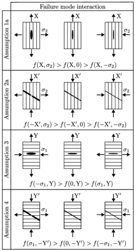
Tsai [2] described the failure mode interaction assumptions for unidirectional lamina that are illustrated in Figure 1. Those are the same assumptions that Tsai and Melo [5] used to find the range of admissible values for of some composite laminae and recommend a value of as a good approximation for all materials. The assumptions try to be representative of the most common failure mode interactions but in no way exclusive.

|
| Figure 1: Failure mode interactions (after Tsai1992).
In the assumptions: |
3.2 Failure envelope slope at the anchor points
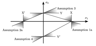
If there is no shear stress (), the envelope of the Tsai-Wu failure criterion intersects the and axes at the same points as the maximum stress failure criterion envelope does. These points are called anchor points because, the shape of the Tsai-Wu failure criterion envelope changes with the interaction term but it always passes through these points. As noted by Tsai [2], the admissible ranges of the slopes at the anchor points of the failure envelope corresponds to the shaded areas in Figure 2.

|
| Figure 2: Admissible ranges of the slopes at the anchor points of the Tsai-Wu failure envelope (after Tsai [2]). |
3.3 Range of admissible values for F₁₂
The interaction term for the Tsai-Wu failure criterion is usually treated as an empiricial constant with the following definition:
|
|
(6) |
where for the failure surface to be closed (this condition can be derived from Eq.(2). Now, in addition to the condition for a closed failure envelope, new upper and lower limits for can be derived from the slope at the anchor points of the previous assumptions.
Assumption 1a
|
where it can be proven that
Assumption 2a
|
where it can be proven that
Assumption 3
|
where it can be proven that
Assumption 4
|
where it can be proven that
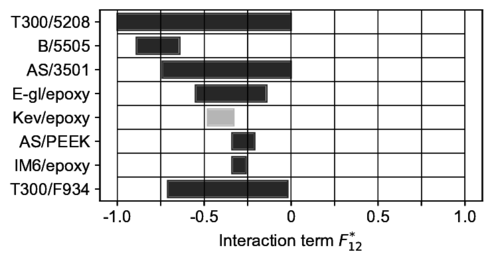
Tsai [2] determined graphically the range of admissible values for for some composite laminae by plotting as a function of the slope at each of the anchor points. Figure 3 shows the range of admissible values for for the same composite laminae but determined with Eq.(7) to (14). The ranges of admissible values found look alike the ones shown in Tsai and Melo [5] but something went unnoticed for the Kevlar/epoxy lamina. For this specific lamina, the upper limit () is less than the lower limit (), which means that it is not possible to meet failure mode interaction assumptions 1a and 4 together.

|
| Figure 3: Admissible ranges of the interaction term
based on assumptions 1a, 2a, 3 and 4. |
3.4 Suitability of the Tsai-Wu’s failure criterion
In Section 3.3, it was proved that there are certain materials whose Tsai-Wu failure envelope cannot satisfy the failure mode interaction asssumptions 1a, 2a, 3 and 4 together. Table 1 summarises the requirements to ensure that the lower limits are always less than the upper limits of the interaction term under any pair of the failure mode interaction asssumptions from the set 1a, 2a, 3 and 4.
| ✓ | ||||
| ✓ | ✓ | ✓ | ✓ | |
| ✓ | ✓ | ✓ | ✓ | |
| ✓ | ✓ | ✓ | ✓ |
4 Test results for anchor points
A common testing procedure [6] is to find the strength of unidirectional lamina from bidirectional laminate and the strength of unidirectional lamina from unidirectional laminate. Instead of having four simple stress states to define a failure envelope, these test methods result in two combined stress states and two simple stress states. The following procedure is proposed in order to define the strength terms and of the Tsai-Wu failure criterion such that the failure envelope passes through up to four specific combined stress states and meets the failure mode interaction assumptions:
- Find the strength terms and of the Tsai-Wu failure criterion as usual.
- Find the interaction term that best fits the failure envelope to your failure mode interaction assumptions (see Section 3.3).
- Find the actual stress states of the lamina at failure when testing the laminate specimen.
- Solve the linear system to find the terms of the strength tensors and that force the envelope to pass through the actual stress states at failure:
(15) - Find the intercepts of the Tsai-Wu failure envelope with the coordinate axes in the stress space.
- Recalculate the range of admissible values for the interaction term .
- Verify the error of the new Tsai-Wu failure envelope at the points corresponding to the actual stress states at failure. If needed, iterate from step 4 until the error is considered to be satisfactorily small. For most cases, this procedure should easily converge in very few steps.
For example, the Tsai-Wu failure envelope was found for a unidirectional high strength carbon fibre / epoxy prepeg lamina with four differente methods. Figure 4 shows the Tsai-Wu failure envelopes when it is generated whith the most commonly recommended values for (0 and -0.5), the interaction term that best fits the failure envelope to the failure mode interaction assumptions, and the interaction term that best fits the failure envelope to the failure mode interaction assumptions and also passes through two composed stress states corresponding to bidirectional laminate tests that have the same longitudinal failure strain.

|
| Figure 4: Example: Tsai-Wu failure envelopes (=0)
in stress space (up) and strain space (down). |
5 Conclusions
Tsai [2] presented the idea of finding the range of admissible values for the interaction term from general failure mode interaction assumptions. Applying the same idea, this paper provides closed form expressions to find the interaction term for some of the most common failure assumptions found in composite materials. If no test data is available for a particular material, these expressions may be employed to find a range of admissible values for the interaction term . Using the recommended value for all materials is discouraged in favour of applying this procedure for each particular material.
The expressions to find the interaction term based on general failure mode interaction assumptions also show that the Tsai-Wu failure criterion cannot satisfy all the assumptions unless the material strength parameters meet certain relationships. Therefore, the suitability of the Tsai-Wu failure criterion has been narrowed to certain materials.
Last, regarding the strength parameters that are used to define the Tsai-Wu failure envelope, it has been noted that the strength parameters of a composite material can be determined from unidirectional and bidirectional laminates. A procedure has been proposed to use the actual combined stress state at failure of these specimens to define the Tsai-Wu failure envelope.
Acknowledgement
This paper and the research behind is a joint effort between Ingeniacity and the University of Surrey. Ingeniacity is a company specialised in interdisciplinary and innovative engineering. Composite materials in the naval, automotive and energy sectors are one of the main areas of expertise of Ingeniacity.
Nomenclature
Ultimate tensile strength in fibre direction 1.
Ultimate compressive strength in fibre direction 1.
Ultimate tensile strength in direction 2.
Ultimate compressive strength in direction 2.
Stress in direction when the tensile stress in direction reaches failure.
Stress in direction when the compressive stress in direction reaches failure.
Ultimate shear strength.
References
[1] S. W. Tsai and E. M. Wu, “A general theory of strength for anisotropic materials,” Journal of Composite Materials, vol. 5, no. 1, pp. 58–80, 1971.
doi: 10.1177/002199837100500106.
[2] S. W. Tsai, Theory of Composite Design. Think Composites, 1992, isbn: 0-9618090-3-5.
[3] I. I. Gol’denblat and V. A. Kopnov, “Strength of glass-reinforced plastics in the complex stress state,” Polymer Mechanics, vol. 1, pp. 54–59, 1965.
[4] E. Ashkenaz, “Problems of the anisotropy of strength,” Polymer Mechanics, vol. 1, 60–70, 1965. doi: https://doi.org/10.1007/BF00860686.
[5] S. W. Tsai and J. D. D. Melo, Composite Materials Design and Testing: Unlocking mystery with invariants. Stanford Aeronautics & Astronautics, 2015, isbn: 978-0-9860845-0-8.
[6] C. M. H. CMH-17, Volume 1: Polymer Matrix Composites: Guidelines for Characterization of Structural Materials. SAE International, 2017, isbn: 978-0-7680-9145-8.
Document information
Published on 19/06/24
Accepted on 28/08/23
Submitted on 22/05/23
Volume 08 - COMUNICACIONES MATCOMP21 (2022) Y MATCOMP23 (2023), Issue Núm. 5 - Materiales y Estructuras, 2024
DOI: 10.23967/r.matcomp.2024.05.08
Licence: Other