1. Introduction
The Automated Tape Laying (ATL) process with in-situ consolidation has gained relevance in the last few years as an alternative to out-of-autoclave processes, as a less time and energy-consuming process for thermo-plastic-based composite materials. The drawback of this particular process is the impossibility of placing temperature sensors at the point, or points, of interest. Any type of sensor placed at the location of interest will induce a defect and then, the final structure may not meet the required mechanical, geometrical, or esthetical requirements, thus, its quality.
The requirement to guarantee the quality of a structure produced by a composite material manufacturing process has been the object of recent studies. Those studies have included the use of advanced mathematical techniques, as presented by [1], where a machine-learning strategy is used as a surrogate model to understand the heat distribution along a unidirectional carbon fibre tape process.
On the other hand, researchers have studied the heat distribution problem from a phenomenological point of view, which includes the use of physical equations to perform simulations leading to a detailed description of the heat flow phenomena. The work of [2] proposes a detailed description of an ATL process with in-situ consolidation, where the process is mathematically modelled using a heat flux balance, coming from an infra-red source identified in [3], and then, the fundamental heat diffusion equation is used to compute the temperature distribution along the composite material.
Another study performed on a similar ATL process was performed by [4], where the heat source is a gas torch. This process required a detailed characterization of the heat transfer between the composite material and the hot gas flow, which has a high uncertainty related to the dynamical response obtained due to the randomness involve in the convection phenomena. Intending to control the quality of the produced structure, another proposed strategy contemplates the study of the thermal signature of the composite material for adjusting an infra-red heating source power, as proposed by [5], where using thermal imaging is quantified the number of defects created at a composite laminate from 0.762 mm onwards.
The pursuit of quality in this type of process has led researchers to use more controlled heat sources, such as laser beams. Despite its high initial cost, the laser beam guarantees localized heat application as well as constant power at a constant wavelength, as proposed by [6], where a two-dimensional model of an ATL process is simulated to obtain the heat distribution near the consolidation point. Other researchers studied the case when the produced structure requires curved paths using unidirectional fibres. Not only the mechanical response was studied as well as the thermal response, to minimize defects [7].
The former study's main goal is to avoid any type of secondary process while ensuring the structure quality, maintaining the original composite material mechanical performance, and lowering the production time. The common ground for all those studies has been the requirement for a proper thermal characterization of the composite material being processed. Despite the existence of normalized tests for measuring each required property as a function of its temperature, in some cases some of the properties such as the thermal-optical and the thermal-conductivity properties, are not convenient to measure using such standard tests. This inconvenience is caused to how the coupons must be prepared, which can be very expensive or difficult to produce.
This article presents an alternative method for characterising a unidirectional carbon fibre-based prepreg composite material, using both standard and non-standard procedures, to obtain all the required thermal properties, as a function of its temperature, to provide sufficient information to a Digital Twin-based simulation process for an ATL process. This simulation will allow using state estimation strategies for satisfying the control requirements of a Model Predictive Control strategy.
2. Automated Tape Laying Process
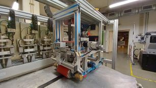
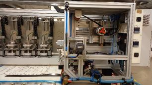
The ATL process consists of continuously heating up a tape of unidirectional carbon fibres pre impregnated with a thermoplastic matrix and then, consolidate them on top of a mould to manufacture a structure. The machine, object of this study, is an ATL machine located at INEGI’s laboratories in Portugal, which main heat source is an infra-red lamp. Figure 1(a) shows a general overview of the ATL machine, and Figure 1(b) presents a general overview of the composite material path towards the heating element.
|
|
| (a) General overview of the ATL machine assembly | (b) Composite material path and heating zone (red delimited zone) |
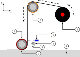
To better understand the machine assembly, a schematic is presented in Figure 2, listing all the involved components.
2.1. Heating equation modelling
As the heating process is the core of the ATL process, it needs to be studied using physical formulations. As described in [2] and [3], the modelling for the heating process consists of solving a two steps finite differences equations, the first step involves a heat flux balance, equation (1) and equation (2), and the second step, involves solving the heat diffusion equation, equation (4), using the results obtained at the first step using equation (3).
|
|
(1) | |
|
|
(2) | |
|
|
(3) |
Where is the radiosity and is the irradiation of the composite material. , and are the reflectivity, transmissivity, and emissivity thermal-optical properties of the composite material respectively, all temperature dependent.
|
|
(4) |
Where the subindex denotes an element of the composite material, , , and stands for the composite material density, specific heat as a temperature dependant property, thermal conductivity as a temperature dependant property and the incoming radiation as a temperature dependant thermal-optical property.
3. Thermal characterization of composite materials
The challenge researchers must overcome while performing a thermal characterization of composite materials are focused on the thermal conductivity and the thermal-optical properties. For some simulation models, researchers considered constant property values, which may cause significative deviations in the results obtained when comparing theoretical results with experimental results. Despite the existence of standard test procedures for measuring the thermal properties of materials, they are mostly focused on isotropic materials.
3.1. Specific heat
To measure the specific heat of composite materials is used the Differential scanning calorimetry procedure. This test consists of measuring the heat flux between a known material and an unknown material to estimate the heat absorbed, or released, according to a change in temperature. The test procedure is normalized in the ASTM E 1269-01 norm. This test procedure has no limitations for measuring composite materials.
3.2. Thermal conductivity
The thermal conductivity is measured by applying a known amount of heat at a surface, measuring its temperature at that surface and then, measuring the temperature at an opposite surface as function of time. This procedure is known as the Flash method, and the typical test procedure assembly is presented in Figure 3.
The work of [8] reviews different theoretical approximations to describe the heat distribution along a solid, from a micro-mechanical and macro-mechanical points of view. Those models must be selected depending on the level of precision required, and how well characterized are its components. On a similar study presented by [9], a meso-scale approximation is used for compute the thermal conductivity of composite materials, where a detailed characterization of each component of the composite material is required, and it is considered that the fibres are long unidirectional cylinders.
On the other hand, the work of [10] designed an enclosure, well isolated from the outside, to replicate a one-dimensional thermal conductivity process, applying a known temperature at once end of the test specimen and cooling it down at the opposite end with cooling oil with a very controlled temperature. The goal is to measure the temperature distribution along the test sample to determine a thermal conductivity value using a set of energy balance equations. The drawback of this test is that all the temperatures must stabilize to calculate the thermal conductivity.
3.3. Thermal-optical properties
For measuring the thermal-optical properties, some researchers measure the irradiance of the composite material at the temperature, as presented by [11], and then, calibrate the heat source to emit power at such wavelength. This approach represents a problem when the process requires to constantly reinitialize to lay down a new layer, increasing the uncertainty of the obtained results and deviations with respect to measurements.
4. Materials and methods
The composite material to be characterized is a unidirectional carbon fibre prepreg which matrix is Polyamide 6 from Toray Co®.
4.1. Density measurements
The density measurements are performed using the ASTM D 792 – 07 standard test, with a KERN ADB 600-C3 analytical balance.
4.2. Specific heat measurements
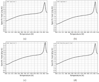
The specific heat measurements are performed according to the ASTM E 1269 – 01 standard test, using a Differential Scanning Calorimeter Q200 from TA Instruments. The tests are performed with a temperature rate of 20 ºC/min.
4.3. Thermal-optical properties
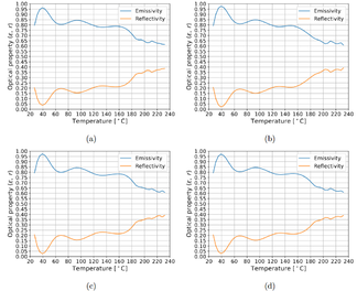
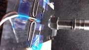
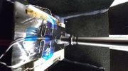
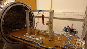
The thermal-optical properties are measured using an in-house designed procedure. This procedure consists of measuring the real temperature of a composite sample, using thermocouples type T. Those thermocouples are suitable for the temperature range required having the lowest uncertainties. At the same time, the temperature of the sample is measured using a pyrometer from Optris CS LT with a focusing lens. The pyrometer is set to measure a black body, this means, . The temperatures are correlated using equation (5). The composite sample is heated up until the desired temperature using an electrical resistor heater. Figure 4 shows the in-house procedure assembly for measuring this property as function of the composite material temperature.
|
|
(5) |
|
|
4.4. Thermal conductivity.
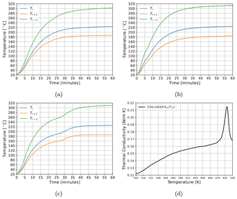
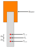
The thermal conductivity is measured using an in-house designed procedure. This procedure consists of heating up a narrow 1 cm wide composite material sample to simulate a one-dimensional conductivity phenomenon. The composite material temperature is measured, as function of time, at three locations, separated 10 mm. The measuring sensor used are type T thermocouples.
This procedure is performed inside a vacuum chamber, to avoid the convective heat transfer effects and minimizing the thermal losses due to external sources of radiation. Figure 5 shows a general assembly, as well as the main measurement locations, for the in-house designed test procedure.
|
|
5. Results
5.1. Density measurements
| Sample | Weight in Air [g] | Weight in water [g] | Density [g/cc] | Sample | Weight in Air [g] | Weight in water [g] | Density [g/cc] |
| 1 | 2,125 | 0,541 | 1,338 | 6 | 1,992 | 0,491 | 1,324 |
| 2 | 1,684 | 0,483 | 1,398 | 7 | 1,826 | 0,48 | 1,3566 |
| 3 | 1,516 | 0,405 | 1,361 | 8 | 2,16 | 0,523 | 1,3194 |
| 4 | 1,964 | 0,586 | 1,421 | 9 | 1,553 | 0,367 | 1,3094 |
| 5 | 1,558 | 0,361 | 1,298 | 10 | 1,625 | 0,449 | 1,3818 |
| Mean | 1,8003 | 0,4686 | 1,3507 | ||||
| STD | 0,245848 | 0,073901 | 0,040298 |
5.2. Specific heat
5.3. Thermal-optical properties
5.4. Thermal conductivity
5.5. Automated tape laying simulation and real measurements
|
|
6. Conclusions
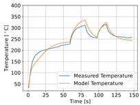
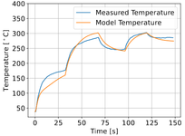
The proposed methodology for thermal characterization of a composite material, specifically unidirectional prepregs, contributed to predict the temperature of the ATL process using a detailed mathematical model. Even the predictions are not perfect, they minimize the uncertainty generated by considering the thermal properties as constants, accounting for the transient phase of the heating process. Using the measured properties, allowed the model to fine adjust the parameters that are related with empiric correlations, such as convective heat losses and geometrical variations of the composite material, lowering the number of degrees of freedom in which the model could oscillate. The proposed methodology for measuring the thermal-optical properties of a composite material, is significantly cheaper than performing laboratorial tests to each constituent of the composite material and then, performing probabilistic simulations around the variations the production process may have. On the other hand, the thermal conductivity procedure proposed, despite requiring a specialized equipment such as a vacuum chamber, it results in a faster and cheaper method for measuring such property, compared with the Flash method, or the proposed methods in literature.
References
[1] M. Römer, J. Bergers, F. Gabriel, and K. Dröder, ‘Temperature Control for Automated Tape Laying with Infrared Heaters Based on Reinforcement Learning’, Machines, vol. 10, no. 3, p. 164, Mar. 2022, doi: 10.3390/machines10030164.
[2] J. de S. Rodrigues, P. T. Gonçalves, L. Pina, and F. G. de Almeida, ‘Modelling the Heating Process in the Transient and Steady State of an In Situ Tape-Laying Machine Head’, J. Manuf. Mater. Process., vol. 6, no. 1, p. 8, Jan. 2022, doi: 10.3390/jmmp6010008.
[3] J. de S. Rodrigues and P. Teixeira, ‘Model for an Automated Tape Laying Process: Heat source Identification’, in DCE21: Symposium on Mechanical Engineering: Book of Abstracts and Invited Lectures, FEUP Edições, 2021, pp. 29–31.
[4] M. Moghadamazad and S. V. Hoa, ‘Models for heat transfer in thermoplastic composites made by automated fiber placement using hot gas torch’, Compos. Part C Open Access, vol. 7, p. 100214, Mar. 2022, doi: 10.1016/j.jcomc.2021.100214.
[5] P. D. D. Juarez and E. D. D. Gregory, ‘In Situ Thermal Inspection of Automated Fiber Placement for manufacturing induced defects’, Compos. Part B Eng., vol. 220, no. January, p. 109002, Sep. 2021, doi: 10.1016/j.compositesb.2021.109002.
[6] A. Danezis, D. Williams, M. Edwards, and A. A. Skordos, ‘Heat transfer modelling of flashlamp heating for automated tape placement of thermoplastic composites’, Compos. Part Appl. Sci. Manuf., vol. 145, no. March, p. 106381, 2021, doi: 10.1016/j.compositesa.2021.106381.
[7] A. Rajasekaran and F. Shadmehri, ‘Steering of carbon fiber/PEEK tapes using Hot Gas Torch-assisted automated fiber placement’, J. Thermoplast. Compos. Mater., p. 08927057211067962, Feb. 2022, doi: 10.1177/08927057211067962.
[8] S. Zhai, P. Zhang, Y. Xian, J. Zeng, and B. Shi, ‘Effective thermal conductivity of polymer composites: Theoretical models and simulation models’, Int. J. Heat Mass Transf., vol. 117, pp. 358–374, 2018, doi: 10.1016/j.ijheatmasstransfer.2017.09.067.
[9] K. Pietrak and T. Wiśniewski, ‘A review of models for effective thermal conductivity of composite materials’, J. Power Technol., vol. 95, no. 1, pp. 14–24, 2015.
[10] M. Villière, D. Lecointe, V. Sobotka, N. Boyard, and D. Delaunay, ‘Experimental determination and modeling of thermal conductivity tensor of carbon/epoxy composite’, Compos. Part Appl. Sci. Manuf., vol. 46, no. 1, pp. 60–68, 2013, doi: 10.1016/j.compositesa.2012.10.012.
[11] O. Baho, G. Ausias, Y. Grohens, M. Barile, L. Lecce, and J. Férec, ‘Automated fibre placement process for a new hybrid material: A numerical tool for predicting an efficient heating law’, Compos. Part Appl. Sci. Manuf., vol. 144, no. September 2020, p. 106360, May 2021, doi: 10.1016/j.compositesa.2021.106360.
Acknowledgements.
This project has received funding from the European Union's Horizon 2020 research and innovation programme under grant agreement No 101006860
Document information
Published on 30/07/23
Accepted on 05/06/23
Submitted on 21/05/23
Volume 08 - COMUNICACIONES MATCOMP21 (2022) Y MATCOMP23 (2023), Issue Núm. 1 - Caracterización - Sostenibilidad y Reciclaje, 2023
DOI: 10.23967/r.matcomp.2024.01.06
Licence: Other
Share this document
Keywords
claim authorship
Are you one of the authors of this document?
