1 Introduction
One of the concerns of the aeronautic industries is the impact behaviour of thin structures in the aircraft as low velocity impacts can significantly reduce the residual structural strength [1]. Thin plies (<75 gsm) in thin laminates resulted in extensive fibre damage during impact and reduced the CAI strength when compared to intermediate and thick plies [2, 3]. Studies showed that ply level hybridization, ie, mixing plies of different thicknesses in an attempt to enhance the target response, helped to improve the structural performance. In addition, impact loads are unsymmetrical in the thickness direction and hence the conventional idea of symmetric laminates need to be challenged. It is important to move away from the conventional symmetry design which will also enhance the stacking sequence design space.
In this study, we use ply grade hybridization and unsymmetrical laminate designs as an effort to improve the impact and CAI strength of thin laminates. The work was performed at AMADE research group, University of Girona in collaboration with Airbus Airnet project under Dr. Peter Linde.
2 Methodology
2.1 Material and Laminates
In this study, we used two different material systems: uni-directional prepreg tapes and non-crimp fabric (NCF), both of the same T700/M21 carbon-epoxy. We used three ply grades of the UD plies namely thick (268 gsm), intermediate (134 gsm) and thin plies (75 gsm). NCF come in bi-axial blankets of [0/45] and [0/-45]. Similarly, for the NCF: intermediate (134 gsm) and thin plies (67 gsm).
Table 1. Different laminates studied
| Laminate & Ply thickness (mm) | Layup | Lam. thickness
(mm) |
| H-268
(0.262) |
[45/-45/0/90]$ | 1.83 |
| H-134
(0.131) |
[45/-45/0/45/-45/90/0]$ | 1.7 |
| H-75
(0.075) |
[45/-45/0/45/-45/90/0/45/-45/90/0]$ | 1.58 |
| H-75-H1
(0.075 & 0.131) |
[45/-45/45/-45/90/0134/45/-45/90]$ | 1.59 |
| H-75-H2
(0.075 & 0.262) |
[45/-45/45/-45/90/0268/45/-45/90]$ | 1.65 |
| NCF-Int | [45/0/-45/90/22.5/-22.5]S | 1.61 |
| NCF-Thin | [(45/0)/(-45/90)/(45/0)/(-45/90)/(45/0)/(-45/0)]S | 1.61 |
| NCF-UHB | [(90/-45)/(0/45)/(90/-45)/(0/45)/(90/-45)/(0/45)/(90/45)/(0/45)/(45/0)268/(-45/90)268] | 1.61 |
| NCF-UHT | [(90/45)268/(0/-45)268/(-45/0)/(45/90)/(-45/0)/(45/90)/(-45/0)/(45/90)/(-45/0)/(45/90)] | 1.61 |
| L1
(0.131) |
[452/-452/90/03/90/-452/452] | 1.7 |
| L8
(0.131) |
[45/02/−45/902/0/902/−45/02/45] | 1.7 |
| L9
(0.131) |
[45/0/−45/902/03/902/−45/0/45] | 1.7 |
Table 1 presents the different laminates studied in this work, the ply grades/thicknesses used and the corresponding laminate thicknesses. H-268, H-134 and H-75 (all made of UD plies) are the baselines made of thick, intermediate and thin plies respectively. NCF-Int and NCF-Thin are the baselines (made of NCF) using intermediate and thin plies, respectively. H-75-H1 and H-75-H2 are thin ply dominant hybrid laminates, but mixing intermediate and thick 0 plies, respectively. NCF-UHB and NCF-UHT are hybrid unsymmetrical laminates made of intermediate and thin plies, where NCF-UHB has the thicker plies placed at the non-impacted side and the NCF-UHT at the impacted side. L1, L8 and L9 are laminates made of intermediate plies but with clusters (where a cluster of 2 intermediate plies refers to a thicker ply).
2.2 Experimental
We performed impact tests on specimens of dimensions 150x100 mm, in accordance with the ASTM D7136/7135-15 standard using a CEAST Fractovis Plus instrumented drop-weight tower.Total mass of the impactor was set to 3 kg and a 16mm steel hemispherical indenter was used. Impact energies were defined according to the laminate thicknesses.Post impact compressive strength was evaluated through CAI tests using an MTS INSIGHT 300 machine with a 300 KN load cell following the ASTM D7137/D7137M-15 standards. An anti-buckling device was used along with the fixture to ensure proper specimen failure.
2.3 Numerical
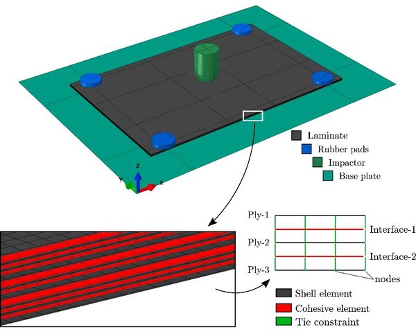
Laminate L1, L8 and L9 were selected through optimization followed by virtual testing through finite element simulations. We used Abaqus/Explicit conventional shell elements (S4R) to model the plies, and zero thickness cohesive elements (COH3D8) to model the interface between the plies. Progressive intraply damage was accounted using continuum damage model proposed by Maimi et al.[7]. The cohesive constitute model for the interface was proposed by Gonzalez et al. [8] and both these models are implemented in a VUMAT user-written subroutine.
The CAI simulation was performed using a RESTART option in Abaqus/Explicit, where apart from the standard, a non-standard anti-buckling fixture was accounted in the model. Reader is referred to [4] for more details on the numerical model.
3 Results & Discussion
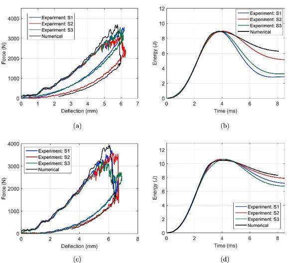
Figure 2 presents the impact curves of the baseline laminate H-134 from both experimental and numerical results of 8.9 and 10.5 J. The force-deflection and energy curves show that the numerical model I in very good agreement with the experimental curves. The load drops seen in the force-deflection curves are attributed to the fibre damage at the non-impacted side of the laminate.
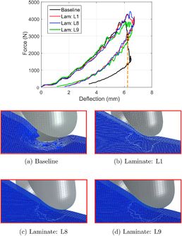
Using the virtual testing framework, out of 30 proposed laminates, L1, L8 and L9 performed better over the baseline H-134, in terms of the CAI strength. L1, L8 and L9 improved the CAI strength by 29%, 31% and 29% respectively over the baseline. Figure 3 shows the comparison of the force-displacement curves of these three laminates against the baseline for the 10.5 J impact. The sudden load drop is mitigated in the proposed laminates which have thicker plies. These plies help to mitigate fiber damage at the non-impacted side through more energy dissipation through delaminations. The same figure shows in detail the difference in the fiber damage for the baseline under the impactor compared with the proposed laminates. Baseline exhibited fiber damage locally under the impactor in all the plies, whereas the hybrid laminates mitigated the load drop and constrained the fiber damage only to the last ply [4].
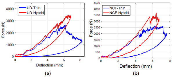
Figure 4 compares the baseline laminates and the proposed hybrid laminates with UD plies (a) and NCF(b). Both the proposed hybrid laminates (H-75-H2 and NCF-UHB) mitigated the fiber failure compared to the thin ply counterparts as seen in the curves. Addition of thicker plies to thin plies helped to dissipate energy through matrix cracks and delaminations and thereby reducing the fiber damage.
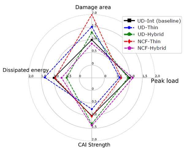
Figure 5 presents the different impact damage resistance parameters and the CAI strength from the 10.5 J impact. Thin ply laminates exhibit low resistance to impact and a low CAI strength when compared to the proposed hybrid laminates.
Compared to the UD hybrid laminates, the NCF proposed hybrid laminates possessed better CAI strength.
4 Conclusions
In the quest to improve the impact damage tolerance of thin ply thin laminates, in this study we have aimed to incorporate ply grade hybridization and unsymmetrical designs. This strategy is economically feasible as no external reinforcement is added, whereas only different ply grades have to be added at the optimum through-the-thickness locations of the laminate. The addition of thicker plies has helped to mitigate extensive fiber damage through matrix cracks and delaminations. This change in damage morphology dramatically improves the CAI strength (up to 40%) over the aerospace baseline laminate made of intermediate grade plies. We have pushed the boundaries of damage tolerant designs through novel stacking sequences and proved that through judicious tailored laminate designs, it is feasible to substantially improve the impact and post-impact response without added costs.
Acknowledgements
The first author would like to thank the Generalitat de Catalunya for the FI-DGR pre-doctoral grant (2018 FI-B2 00118). The authors would like to thank the Spanish Ministerio de Ciencia, Innovacíon y Universidades for the grant coded RTI2018-097880-B-I00 and RTI2018-099373-B-I00. The authors acknowledge Airbus, Dayton Research Institute and University of Porto for the collaboration in the Airnet project.
References
[() ] S. Abrate, Impact on Composite Structures, 2005
[2] A. Sasikumar, D. Trias, J. Costa, J. Orr, P. Linde, Effect of ply thickness and ply level hybridization on compression after impact strength of thin laminates, Compos. Appl. Sci. Manuf., 121 (2019), pp. 232-24
[3] A. Sasikumar, D. Trias, J. Costa, N. Blanco, J. Orr, P. Linde, Impact and compression after impact response of thin laminates of spread-tow woven and non-crimp fabrics, Compos. Struct., 215 (2019), pp. 432-445
[4] A. Sasikumar, J. Costa, D. Trias, J. Llobet, I.R. Cózar, A. Turon, P. Linde, A virtual testing based search for optimum compression after impact strength in thin laminates using ply-thickness hybridization and unsymmetrical designs, Compos. Sci. Technol., 196 (2020), pp. 108188
[5] A. Sasikumar, D. Trias, J. Costa, V. Singery, P. Linde
Mitigating the weak impact response of thin-ply based thin laminates through an unsymmetrical laminate design incorporating intermediate grade plies, Compos. Struct., 220 (2019), pp. 93-104
[6] A. Sasikumar, S. García-Rodríguez, J. Arbeláez, D. Trias, J. Costa
On how unsymmetrical laminate designs with tailored ply clusters affect compression after impact strength compared to symmetric baseline, Compos. Struct., 238 (2020), p. 111958
[7] P. Maimí, P.P. Camanho, J. Mayugo, C. Dávila
A continuum damage model for composite laminates: Part I–Constitutive model, Mech. Mater., 39 (10) (2007), pp. 897-908
[8] E. González, P. Maimí, A. Turon, P. Camanho, J. Renart, Simulation of delamination by means of cohesive elements using an explicit finite element code, Comput. Mater. Continua (CMC), 9 (1) (2009), p. 51
Document information
Published on 13/10/21
Accepted on 06/10/21
Submitted on 04/10/21
Volume 05 - Comunicaciones Matcomp19 (2021), Issue Núm. 4 - Tesis doctorales presentadas al premio AEMAC a la mejor tesis., 2021
DOI: 10.23967/r.matcomp.2021.10.001
Licence: Other
Share this document
Keywords
claim authorship
Are you one of the authors of this document?
