1 Introduction
Interleaving CoPA veils enhances the interlaminar fracture toughness, impact resistance and impact tolerance; and the improvement accentuates with increased veil fibre areal weight [1-6]. However, an excessive load of veil severely reduces laminate thickness and certain in-plane mechanical properties [3,6,7]. To minimize this trade-off, we used two types of light (4 g/m2) co-polyamide (CoPA) veil.
2 Materials and Methods
2.1 Materials
Laminates were manufactured using (0°/45°) and (0°/-45°) non-crimp fabrics (NCFs) made of T700GC carbon, which are commercialized by Chomarat under the brand name C-PLYTM. The fibre areal weight of the blankets was 134 g/m2 (67 g/m2 per unidirectional ply).
Two types of CoPA veils were selected as toughening agent: V1 and V2. Their fibre diameter was 37±4 μm and 11±2 μm, respectively (± signifies standard deviation), whereas their fibre areal weight was 4 g/m2 in both cases. For further details of the veils’ architecture as well as the laminates’ manufacturing process (resin transfer molding), the reader is referred to [8].
2.2 Experimental campaign
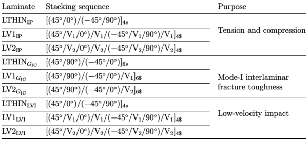
Table 1 Laminates devised for in-plane (tension and compression), mode-I interlaminar fracture toughness and low-velocity impact experiments (impact energy of 14 J). Non-crimp fabric blankets are indicated with parenthesis. The $ sign signifies only one veil in the symmetry plane.
The nominal thickness of baseline and interleaved specimens was 2.2 mm for in-plane and low-velocity impact experiments, whereas that of double cantilever beam samples (DCB) was approximately 3.7 mm.
2.3 X-ray tomography inspection
The experimental campaign was accompanied with two different types of X-ray tomography (Figure 1):
- Micrometric resolution X-ray tomography to understand the impact response of baseline and interleaved laminates (X-ray tomography system in Girona, for further details of the equipment refer to [8-9]),
- nanometric resolution X-ray tomography to gain insight into the microstructure of baseline and interleaved laminates as well as into the fracture process zone of DCB specimens (Zeiss 160 kVp Versa 510 scanner at the μ-VIS X-ray Imaging Centre, University of Southampton).
3 Results and Discussion
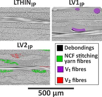
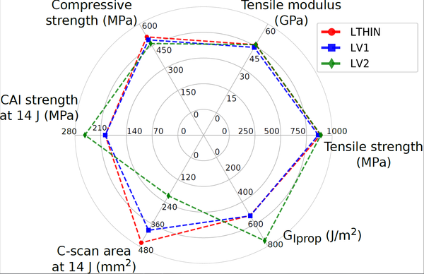
Figure 2 illustrates the effect interleaving has on interface thickness, while Figure 3 summarizes the mechanical properties of the thin-ply baseline and interleaved configurations. The success of the initial objective is evident: interleaving V2 veils improves impact resistance, tolerance and mode-I interlaminar fracture toughness with minimum reduction of tensile and compressive properties.
Interleaving both types of veil into the interfaces of the thin-ply laminate did not increase the baseline laminate thickness because of the combination of low veil fibre areal weight (4 g/m2) and resin transfer moulding manufacturing (all the laminates fitted within the same mould). The lack of porosity is also attributed to the low fibre areal weight of the veils: light veils allow through-the-thickness resin flow [7,10]. Regarding the adhesion between veil fibres and resin, the sub-micron resolution μCT inspections demonstrated consistent debonding between V1 fibres and the surrounding resin (refer to LV1IP in Figure 2). In contrast, the V2 fibres displayed almost no debonding with the resin. Therefore, V2 fibres have better
adhesion with HexFlow®RTM6 epoxy than V1 fibres do.
The tensile modulus and strength of LV1IP and LV2IP are closely connected to the veil fibre diameter (Figures 2-3). The tensile properties of LV2IP are similar to those of LTHINIP because both laminates have the same nominal thickness, fibre volume fraction and (overall) interface thickness (the V2 fibres did not increase the interface thickness except for the regions where they agglomerated, Figure 2). Provided that LV1IP also has a similar nominal thickness and fibre content, the mild decrease of tensile properties can only be attributed to the higher diameter of V1 fibres (the thick V1 fibres increased the interface thickness, compacted locally the carbon plies and reduced carbon uniformity across the thickness, Figure 2).
LV1IP and LV2IP decreased the compressive strength of LTHINIP by 4% and 9% (Figure 3). Compressive strength depends on the ability of the matrix to prevent fibre buckling [7]. Compressive loads rotate the carbon fibres and generate shear stresses that, in turn, further kink the fibres until catastrophic buckling occurs [11]. Therefore, we postulate that interleaving ductile veils reduces the pristine shear strength of the matrix (at least at the low strain-rate of the test [12,15]). Further work will be devoted to correlate veil properties (veil fibre diameter, veil fibre adhesion...) with matrix shear strength.
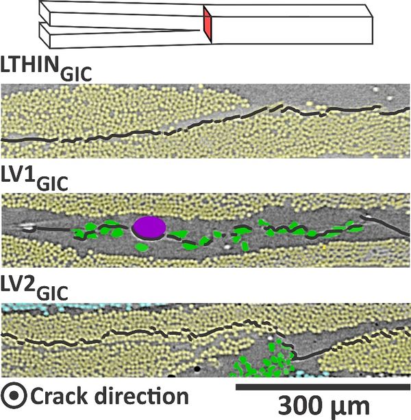
Regarding mode-I interlaminar fracture toughness, crack propagation is mainly controlled by the adhesion between veil fibres and resin. Fibres with a low adhesion (the V1 fibres) promote crack growth by debonding from the resin. Fibres with a higher adhesion (the V2 fibres) deviate crack growth away from the veil (Figure 4) [13]. In LV1GIC, the mode-I crack confined itself into the 0°/0° interface through interaction with the V1 fibres. In LV2GIC, the crack deviated from the 0°/0° interface to the surrounding 0° plies.
Figure 3 Mechanical properties of the thin-ply baseline (LTHIN) laminate and laminates interleaved with V1 or V2 veils (LV1 and LV2).
LV2GIC enhanced GIinit and GIprop by 101% and 43% compared to LTHINGIC, while LV1GIC only enhanced GIinit by 12% (Figure 3). The relation between mode-I interlaminar fracture toughness and veil fibre-resin adhesion is contrary to the one observed in conventional-ply laminates [13]. In those systems, the veil with higher adhesion (V2) results in the lower GIC values because it deviates crack propagation from the resin interface (full of veil) to the interfacial region between resin and structural fibres (depleted of veil). The difference is that V2 deviated crack propagation not to the interfacial region but into the 0° plies (Figure 4), which obviously increased the initiation energy (the crack required extra-energy to circumvent the V2 fibres and penetrate into the tows). The reason why V2 deviated crack propagation into the intralaminar region is probably a combination of several factors such as the small interface thickness of thin-plies, the shape distortions induced by the NCF stitches and the low veil fibre diameter preventing resin accumulation in the interfaces. Regarding LV1GIC, GIprop was unaffected because of the low surface area covered by V1 fibres (22%): the crack encountered few veil fibres during its propagation.
Figure 4 Sub-micron resolution μCT cross-sections depicting the fracture process zone of LTHINGIC, LV1GIC and LV2GIC double cantilever beam specimens. The crack grows towards the reader.
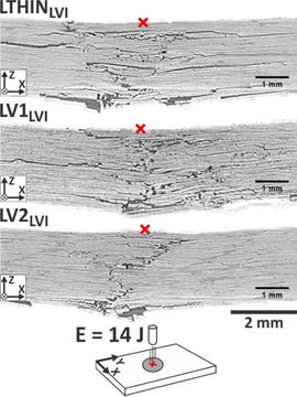
The positive and subtle effects that V2 and V1 veils have on mode-I interlaminar fracture toughness are also replicated on impact resistance: LV2LVI and LV1LVI reduced LTHINLVI's C-scan damage area by 55% and 15% for impact at 14 J. Besides this, LV2LVI enhanced the baseline CAI strength by 28% (Figure 3). The impact damage scenario of LV2LVI evidences that V2 veils mitigated delamination initiation compared to the non-interleaved laminate (Figure 5). In particular, they arrested delamination induced during the fibre failure event since LTHINLVI develops minimum delamination prior to fibre failure [9]. The reason for the damage suppression is probably that V2 veils enhance the pristine shear strength of the matrix under high-strain rates of the test, which is in agreement with the shear strength reduction under static compression because thermoplastic materials (the veils) suffer strain-rate hardening [12, 15]
LV1LVI featured an impact scenario comparable to that of LTHINLVI, albeit with slightly reduced intensity (Figure 5). This is once again attributed to the low surface area covered by V1 fibres: there is a few number of fibres available to interact with the crack front.
Most of the mechanical properties of interleaved laminates present a common denominator: they would benefit from thinner veil fibres. For a given veil fibre areal weight, the benefits of reducing veil fibre diameter are two-fold: minimizing the increase of interface thickness and improving the surface area covered by veil fibres. This is supported by the experimental observations of Ramírez et al. [3] and Tsotsis et al. [16]: they improved interlaminar fracture toughness and CAI strength by, for a given veil configuration, increasing the surface area covered by veil fibres.
4 Conclusiones
For the same veil fibre areal weight (4 g/m2), interleaving the veil with the lower fibre diameter improved mode-I interlaminar fracture toughness and impact tolerance with minimum penalty of in-plane (tensile and compressive) properties.
The veil fibre diameter was the crucial in determining the tensile properties: the veil with thinner fibres avoided resin accumulation at the interfaces and displayed the same tensile strength, strain-to-failure and longitudinal modulus as the baseline laminate did.
Mode-I interlaminar crack propagation was mainly controlled by the adhesion between fibres (the veil with a suspected higher adhesion deflected crack propagation from the 0°/0° interface into the 0°plies and increased the baseline initiation and propagation energy).
Both types of veil decreased compressive strength by up to 9% because of an increase in the ductile phase surrounding the carbon plies, which favours fibre buckling. However, the veil with thinner fibres arrested the initiation of delamination during impact at 14 J (damage area was reduced by 55%) and improved CAI strength by 28%.
Agradecimientos
The authors thank Chomarat (Le Cheylard, France) for manufacturing the materials used in this study. We acknowledge the support of Dr. Imma Boada and her team (Graphics and Imaging Laboratory, University of Girona) for providing the software Starviewer, the 3D viewer used to render the tomographic slices. We also extend our appreciation to the FEDER-UE and the Spanish government through the Ministerio de Economía y Competitividad under the contract MAT2015-69491-C3-1-R. The first author is particularly grateful for the support received from the Secretaria d’Universitats i Recerca del Departament d’ Empresa i Coneixement de la Generalitat de Catalunya through the pre-doctoral grant 2016FI_B_00551, co-funded by the Fondo Social Europeo (FSE).
Referencias
[1] M. Kuwata, P. J. Hogg, Interlaminar toughness of interleaved CFRP using nonwoven veils: Part 1. Mode-I testing, Composites Part A: Applied Science and Manufacturing 42 (10) (2011) 1551–1559. doi:10.1016/j.compositesa.2011.07.016.
[2] M. Kuwata, P. J. Hogg, Interlaminar toughness of interleaved CFRP using nonwoven veils: Part 2. Mode-II testing, Composites Part A: Applied Science and Manufacturing 42 (10) (2011) 1560–1570. doi:10.1016/j.compositesa.2011.07.017.
[3] V. Ramírez, P. Hogg, W. Sampson, The influence of the nonwoven veil architectures on interlaminar fracture toughness of interleaved composites, Composites Science and Technology 110 (2015) 103–110. doi:10.1016/j.compscitech.2015.01.016.
[4] N. H. Nash, T. M. Young, W. F. Stanley, The reversibility of Mode-I and -II interlaminar fracture toughness after hydrothermal aging of Carbon/Benzoxazine composites with a thermoplastic toughening interlayer, Composite Structures 152 (2016) 558–567. doi:10.1016/j.compstruct.2016.05.086.
[5] N. H. Nash, T. M. Young, W. F. Stanley, The reversibility of Mode-I and -II interlaminar fracture toughness after hydrothermal aging of Carbon/Benzoxazine composites with a thermoplastic toughening interlayer, Composite Structures 152 (2016) 558–567. doi:10.1016/j.compstruct.2016.05.086.
[6] B. Beylergil, M. Tanoglu, E. Aktas¸, Effect of polyamide-6,6 (PA 66) nonwoven veils on the mechanical performance of carbon fiber/epoxy composites, Composite Structures 194 (2018) 21–35. doi:10.1016/j.compstruct.2018.03.097.
[7] S. Miller, G. Roberts, L. Kohlman, P. Heimann, J. Pereira, R. Ruggeri, R. Martin, L. McCorkle, Impact behavior of composite fan blade leading edge subcomponent with thermoplastic polyurethane interleave. 20th International Conference on Composite Materials (Copenhagen, 19-24th July 2015).
[8] S.M. García Rodríguez, J. Costa, V. Singery, I. Boada, J.A. Mayugo. The effect interleaving has on thin-ply non-crimp fabric laminate impact response: X-ray tomography investigation. Compos Part A: Appl Sci Manuf 2018; 107:409–20. doi: 10.1016/j.compositesa.2018.01.023.
[9] S.M. García Rodríguez, J. Costa, A. Bardera, V. Singery, D. Trias, A 3D tomographic investigation to elucidate the low-velocity impact resistance, tolerance and damage sequence of thin non-crimp fabric laminates: effect of ply-thickness, Compos Part A: Appl Sci Manuf 2018; 113:53-65. doi:doi.org/10.1016/j.compositesa.2018.07.013.
[10] N.H. Nash, T. M. Young, W. F. Stanley, An investigation of the damage tolerance of carbon/Benzoxazine composites with a thermoplastic toughening interlayer, Composite Structures 147 (2016) 25–32. doi:10.1016/j.compstruct.2016.03.015.
[11] S. Pinho, R. Gutkin, S. Pimenta, N. Carvalho, P. Robinson, Fibre-dominated compressive failure in polymer matrix composites. In “Failure Mechanisms in Polymer Matrix Composites” (eds. P. Robinson, E. Greenhalgh, and S. Pinho), Woodhead Publishing Series in Composites Science and Engineering, 2012. doi:10.1533/9780857095329.1.183.
[12] D. Bull, S. Spearing, I. Sinclair, Investigation of the response to low velocity impact and quasi-static indentation loading of particle-toughened carbon-fibre composite materials, Composites Part A: Applied Science and Manufacturing 74 (2015) 38–46. doi:10.1016/j.compositesa.2015.03.016.
[13] M. Kuwata, Mechanisms of interlaminar fracture toughness using non-woven veils as interleaf materials. Ph.D. dissertation submitted to the School of Engineering and Materials Science, Queen Mary, University of London (February 2010). URL: https://qmro.qmul.ac.uk/xmlui/handle/123456789/2220
[14] B. Saz-Orozco, D. Ray, W. F. Stanley, Effect of Thermoplastic Veils on Interlaminar Fracture Toughness of a Glass Fiber/Vinyl Ester Composite, Polymers and Polymer Composites 16 (2) (2015) 101–113. doi:10.1002/pc.23840.
[15] D. A. Serban, G. Weber, L. Marsavina, V. V. Silberschmidt, W. Hufenbach, Tensile properties of semi-crystalline thermoplastic polymers: Effects of temperature and strain rates, Polymer Testing 32 (2) (2013) 413–425. doi: 10.1016/j.polymertesting.2012.12.002.
[16] T. Tsotsis, Interlayer toughening of composite materials, Polymer Composites 30 (1) (2009) 70–86. doi:10.1002/pc.20535.
Document information
Published on 12/07/22
Accepted on 12/07/22
Submitted on 12/07/22
Volume 04 - Comunicaciones Matcomp19 (2020), Issue Núm. 4 - Aplicaciones de los materiales compuestos. Nuevos procesos de fabricación y materiales compuestos avanzados., 2022
DOI: 10.23967/r.matcomp.2022.07.026
Licence: Other
Share this document
Keywords
claim authorship
Are you one of the authors of this document?

