Introduction
Composite materials whose geometry includes important bending radii are commonly found in engineering structures, in a wide range of fields such as aeronautics, maritime industry, energy or civil construction [1]. These components’ failure mainly occurs due to interlaminar tensile strength, leading to interlayer delamination [2,3]. It is crucial therefore to determine interlaminar tensile strength (ILTS) if an efficient design is to be achieved. There are several experimental methodologies available to determine ILTS.
Some direct load methods can be found in ASTM C297 [4] and ASTM D7291 [5], while indirect methods are described by Ko [6], Martin [7], Roos [8] and Makeev [9]. Detailed discussions about pros and cons of both methods are presented by Hara [10] and Vänttinen [11]. Also, numerical methodologies to predict ILTS are proposed in several studies, such as those carried out by Avalon [12], Raju [2] and Ross [8] . In this study an indirect load methodology – a four point bending test in accordance with ASTM D6415 is used [13]. In this test a couple of bending moments in the test coupon arms are generated, with the ensuing pure bending of the section studied. This methodology has various advantages over other indirect methods: stress is irrespective of angular position, the bending moment in the tested section is constant, with an ensuing simplification for ILTS calculation and self-alignment of the coupon [14]. In addition, it is a more realistic approach to determining interlaminar tensile strength for many applications with a curved geometry, and authors such as Cui [3] or Jackson [14] in their research validate the use of curved beams under four point bending so as to obtain interlaminar tensile strength values.
A large number of studies focused on the prediction of the in-plane elastic and failure behavior of general textile composites using numerical modelling which allows the incorporation of potentially complex three-dimensional geometric features and advanced material and damage models. Among them, one of the most advanced tools to investigate textile composites with through-the-thickness features such as braided and non-structurally stitched fabric composites (NCF) is currently the software package developed by the team of Verpoest and Lomov at the Katholieke Universiteit Leuven, Belgium, incorporation WiseTex to create the geometrical fabric architecture and Tex- Comp to predict numerically the mechanical properties of the textile composites [15].
Although most models on the in-plane mechanical properties of Z-reinforced composites report close agreement between prediction and experimental results, correlation between simplified and experimentally determined disruptions such as fiber volume fraction and fiber deviation are often missing. Change in local fiber volume fraction was generally either omitted or simplified by assuming a uniformly enhanced fiber compaction across the unit cell, although several studies on Z-reinforced composites have reported significant variations in fiber volume fraction in the presence of the Z reinforcement [16] which can affect the prediction of both elastic constants and initiation of damage.
The tufting process
Tufting is a breakthrough technique with a variation in the stitching technique. It consists of inserting just one needle, taking the thread through the thickness of the reinforcing layered preform, and returning it via the same route, leaving the fibre behind within the structure thanks to the existing friction between the fabrics and the thread [17-19]. This technique stitches the preform without any knots amongst the threads, thus preventing those problems on the surface layers caused by stitching and the ensuing degradation of its mechanical properties.
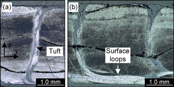
The presence of external ribbons or loops is typical of this process and makes it easily recognizable (Figure 1).This methodology can be regarded as a technical improvement on low-stress stitching technique. Despite these advantages, those textile preforms made by applying this technique demand higher precautions when manipulated, as the thread’s loose-end can be easily pulled out, particularly from its ends [20].
As for the effect of tufting on laminate properties, authors such as Colin de Verdiere [21] compared laminate behaviour and performance under traction, compression, shear and delamination in mode I and II, against non-stitched laminates. Tufting reduces the modulus and strength in the laminate plane under tensile loads, owing to misalignment and damage from the needle. This influence is even more remarkable under compression efforts. As for resistance to delamination, a significant increase could be observed when tufting was used Dell’Anno [22] studied tufting influence on a fibre carbon laminate subjected to Compression
After Impact (CAI). An approximate 26% increase in resistance to compression after impact was obtained. Likewise, in that study, an analytical model for prediction on stitched laminates was developed. Other studies, such as the one by Smith [23] on fracture resistance, demonstrate that resistance to fracture in mode I (GIC) and mode II (GIIC) shows a significant improvement, with a 100% improvement for mode I and a 50% improvement for mode II when compared to UD preimpregnated composites performance.
Mesomechanical approach and representative volume element
The approach object of study is a micro-mesomechanical model, where the micromechanical step follows is the called MMF or MicroMechanics of Failure [24-26]. This section will describe the mesomechanical approach developed for tufted laminate composites. Figure 2 shows the in- and out-of-plane sections of the 2% tufted [0°/90°] twill woven composite [27]. Although differing most from the conventional preforms the following typical fabric defects around the tuft were noted:
- in-plane fiber misalignment, resin rich zones (channels)
- thermal micro-cracking around the tuft
- out of-plane fabric fiber crimp at the tufting seams
- increase in local fiber packing
- resin rich layers to accommodate loop ends
A three-dimensional unit cell model was developed to identify critical changes to the meso-structure of composites due to the insertion of tufts and to predict its effect on the macroscopic response and stress-strain field in the unit cell of the tufted composite.
Each unit cell incorporates a single tuft at its center, which is simplified as cylindrical, straight through-the-thickness entity of uniform cross-section with homogeneous fibrous material properties, aligned with the z directional of the unit cell. The individual thread yarns and thread twist are not considered in the geometry, but accounted for in the adapted material properties.
The tuft is surrounded by fiber-free resin filled zones (resin pocket) which align in each composite layer with the original fiber orientation of the ply. Through all layers the dimensions of the resin rich zones are assumed to be constant.
The individual composite layers are assumed to be uni-directional with orthotropic, transversely isotropic material properties and constant thickness for each ply. In order to accommodate the tuft the fibers of the ply are locally compacted and deviate from the original in-plane ply orientation, creating the resin rich zones.
Fiber waviness due to non-structural stitching and weave is not taken into consideration since micro-graphs confirmed their size to be a magnitude smaller than the tuft induced changes to the meso-structure.
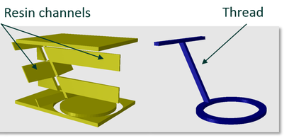
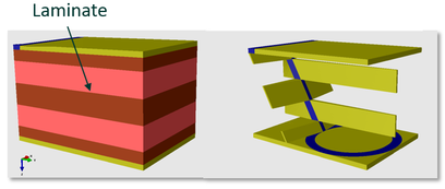
Figure 3 shows the mesomechanical modeling (unit cell) of resin (left) and tufting thread (right) and Figure 4, the mesomechanical modeling (unit cell) of resin (left) and tufting thread (right).
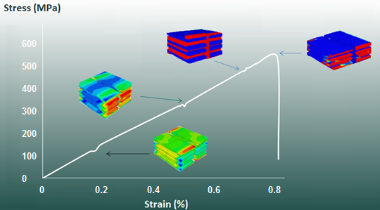
Figure 5 shows the stress-strain curve of a [0/90]s carbon fiber/epoxy (Vf=55%) including a tufted thread subjected to longitudinal tension. The first local failure appears at 105 MPa and corresponds to the initiation of matrix cracking failure mechanism in the 90 degree plies. At 303 MPa, the 90 degree plies fail completely. At 482 MPa, failure occurs at the tufted thread interface and the 0 degree fiber start breaking as well. The final failure is reported at 557 MPa and 0.8% of strain-to-failure.
The thread, fiber and matrix properties used in the analysis are the following (Table 1).
| Material properties | Glass fiber | Carbon fiber | Material properties | Epoxy |
| Ef1 (GPa) | 74.0 | 230.0 | Em (GPa) | 3.30 |
| Ef2=Ef3 (GPa) | 74.0 | 15.2 | νm | 0.35 |
| Gf12=Gf13 (GPa) | 30.8 | 9.6 | ||
| νf21 | 0.2 | 0.2 | ||
| νf32 | 0.2 | 0.2 |
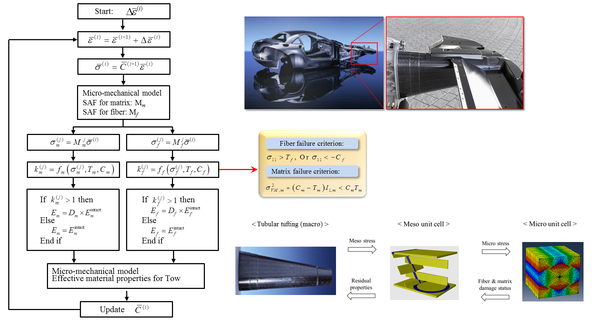
The flow chart of the micro – mesomechanical approach is depicted in Figure 6. First the micromechanical model is applied in order to obtain strains and stress in the micromechanical unit cell. Second the stress amplification factors (SAF) are obtain for both matrix and fiber.
Third, the failure criteria above described area applied including progressive damage. Then, the mesomehanical unit cell is used to relate the meso stresses with micros stresses, obtain the fiber and matrix damage stress and residual properties. The stiffness matrix is then updated and a new step is initiated until final failure.
Theory-Experiment Correlation Studies
To validate the approach presented in this paper, three theory-experiment correlation studies have been performed.
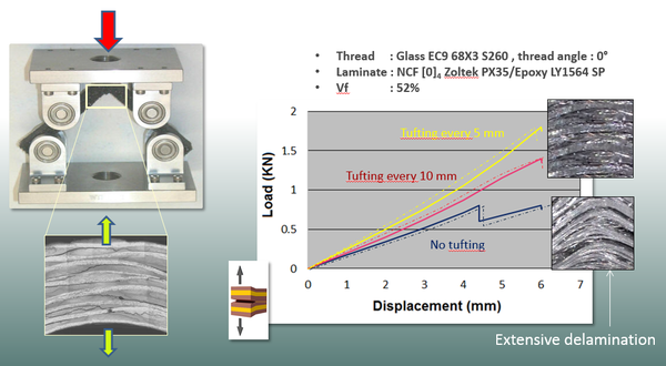
First, the ASTM D6415 standard has been applied to determine the through-thickness normal strength of laminates tufted every 5 and 10 mm and conventional ones. The details of the theory-experiment correlation study are shown in Figure 7. The continuous curves correspond to test data and the non-continuous ones are given by the current approach. In all three cases the correlation is quite accurate.
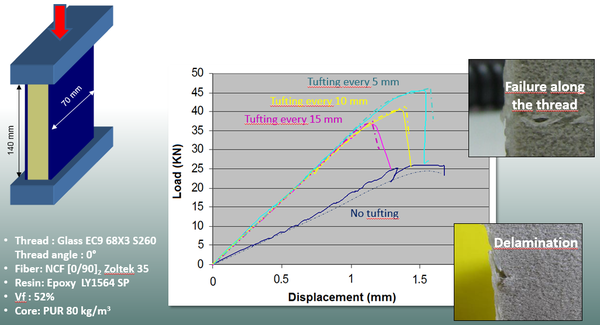
The second correlation study corresponds to the application of standard ASTM C-364. The edgewise compressive strength of short sandwich construction specimens provides a basis for judging the load-carrying capacity of the construction in terms of developed facing stress. The edgewise compression strength of sandwich laminates tufted every 5, 10 and 15 mm and conventional ones. The details of the theory-experiment correlation study are shown in Figure 8. The continuous curves correspond to test data and the non-continuous ones are given by the current approach. In all four cases the correlation is quite accurate.
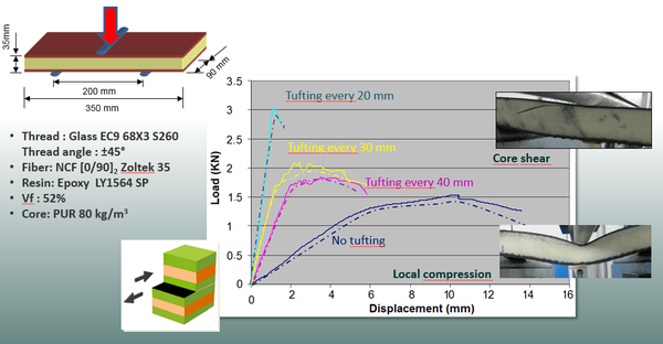
Finally, the third correlation study corresponds to the application of standard ASTM C-393.
Flexure tests on flat sandwich construction may be conducted to determine the sandwich flexural stiffness, the core shear strength and shear modulus, or the facings compressive and tensile strengths. The core strength of sandwich laminates tufted every 20, 30 and 40 mm and conventional ones was obtained. The details of the theory-experiment correlation study are shown in Figure 9. The continuous curves correspond to test data and the non-continuous ones are given by the current approach. In all four cases the correlation is quite accurate
CONCLUSIONS
A mesomechanical composite approach has been presented, which may be combined with a micromechanical model, such as MicroMechanics of Failure or MMF. The type of composite material analyzed here is a conventional ply laminate tufted along its thickness. Based on micromechanics of failure theory, a micromechanical model is presented. In terms of mesomechanics, a new unit cell approach is described and formulated. In order to assess the accuracy of the current approach, three theory-experiment correlations studies have been carried out. ASTM D-6415, ASTM C-364 and ASTM C-393 standards have been applied to carbon fiber/epoxy laminates with and without core. In all cases, the comparison studies between the results from the current approach and test data have produced quite accurate results in all cases.
REFERENCES
[1] Hao W, Ge D, Ma Y, Yao X, Shi Y. Experimental investigation on deformation and strength of carbon/epoxy laminated curved beams. Polym Test 2012;31(4):520–6.
[2] Raju D. Delamination damage analysis of curved composites subjected to compressive load using cohesive zone modelling. QuEST Global; 2014.
[3] Cui W, Jianxin L, Ruo R. Interlaminar tensile strength (ILTS) measurement of woven glass/polyester laminates using four-point curved beam specimen. Composites Part A 1996;27A:1097–105.
[4] ASTM C 297-04. Flatwise tensile strength of sandwich constructions, 1954. W.Conshohocken, PA.
[5] ASTM D 7291-07. Through-thickness ‘flatwise’ tensile strength and elastic modulus of a fiber-reinforced polymer matrix composite material, 2007. West Conshohocken, PA.
[6] Ko W. Delamination stresses in semicircular laminated composite bars, 1988. Nasa Report.
[7] Martin R. Delamination failure in an unidirectional curved composite laminate. National Aeroespatial and Space Administration, Langley ResearchCenter; 1990.
[8] Roos R, Kress G, Barbezat M, Ermanni P. Enhanced model for interlaminar normal stress in singly curved laminates. Compos Struct 2007;80:327–33.
[9] Makeev A, Carpentier P, Shonkwiler B. Methods to measure interlaminar tensile modulus of composites. Composites Part A 2014;56:256–61.
[10] Hara E, Yokozeki T, Hatta H. Comparison of out-of-plane tensile strengths of aligned CFRP obtained by 3-point bending and direct loading tests. Composites Part A 2012;43:1828–36.
[11] Vänttinen A. Strength prediction of composite rib foot corner [Master’s thesis]. Helsinki University of Technology; 2008.
[12] Avalony S, Donaldson S. Strength of composite angle brackets with multiple geometries and nanofiber-enhanced resins. J Compos Mater 2010.
[13] ASTM D6415/D6415M-06a. Standard test method for measuring the curved beam strength of a fiber-reinforced polymer-matrix composite, 1999. West Conshohocken, PA.
[14] Jackson W, Ifju P. Through the thickness tensile stress of textile composites. NASA, Langley Research Center; 1994.
[15] Verpoest, I. and Lomov, S. V. (2005), "Virtual textile composites software WiseTex: Integration with micro-mechanical, permeability and structural analysis", Composites Science and Technology, vol. 65, no. 15-16 SPEC. ISS., pp. 2563-2574.
[16] Freitas, G. (1993), "Z-Fiber Insertion Process for Improved Damage Tolerance in Aircraft Laminates", Proceedings, 25th International SAMPE Technical Conference.
[17] Jackson W, Martin R. An interlaminar tensile strength specimen. Compos Mater Test Des 1993;11:333–54.
[18] C. Sickinger, A. Herrmann, Structural Stitching as a Method to design High-Performance Composites in Future, DLR. Institute of Structural Mechanics. German Aerospace Center, Brunswick, 2001.
[19] Potluri P, Kusak E, Reddy TY. Novel stitch-bonded sandwich composite structures. Compos Struct 2003;59:251–9.
[20] Scarponi C, Perillo AM, Cutillo L, Foglio C. Advanced TTT composite materials for aeronautical purposes: compression after impact (CAI) behavior. Composites Part B 2007;38:258–64.
[21] M. Colin de Verdiere, Effect of Tufting on the Response of Non Crimp Fabrics Composites, in: de ECCOMAS Thematic Conference on Mechanical Response of Composites, Porto, Portugal, 2007.
[22] Dell’Anno G, Cartié DD, Partridge IK, Rezai A. Exploring mechanical property balance in tufted carbonfabric/epoxy composites. Composites Part A 2007;38:2366–73.
[23] Smith P. Carbon fibre reinforced plastics-properties. Compr Compos Mater 2000;2.04:107–50.
[24] S.K. Ha, K.K. Jin, Y. Huang, Micro-Mechanics of Failure (MMF) for Continuous Fiber Reinforced Composites, Journal of Composite Materials, 42(18): 1873–1895, 2008.
[25] K.K. Jin, Y. Huang, Y.H. Lee, S.K. Ha, Distribution of Micro Stresses and Interfacial Tractions in Unidirectional Composites, Journal of Composite Materials, 42(18): 1825–1849, 2008.
[26] S.K. Ha, K.K. Jin, Y. Huang, Effects of Fiber Arrangement on Mechanical Behaviour of Unidirectional Composites, Journal of Composite Materials September 2008 42: 1851-1871, 2008.
[27] J.G.W. Treiber, Performance of tufted carbon fiber/epoxy composites, PhD Thesis, 2011.
Document information
Published on 14/10/18
Accepted on 14/10/18
Submitted on 14/10/18
Volume 02 - Comunicaciones Matcomp17 (2018), Issue Núm. 4 - Comportamiento en servicio de los materiales compuestos (2), 2018
DOI: 10.23967/r.matcomp.2018.10.014
Licence: Other
Share this document
Keywords
claim authorship
Are you one of the authors of this document?

