Abstract
This paper aims to investigate the uplift behavior coupled with the non-linearity both in material properties and in geometry deformations of a typical gantry crane under near-field ground motions. First, the highly nonlinear and time variable model considering the uplift-available boundary condition based on the theory of Mohr-Coulomb friction is established of the gantry crane using the OpenSees platform. Then, a series of time-history analyses on this model structure is performed under three near-field seismic loadings with different exceeding probabilities. Furthermore, the comparison between the uplift-available gantry crane and the fixed crane is also carried out to provide in-depth insight into the structural responses under different boundary conditions. Finally, coupling with the material and geometry inelastic behavior, the uplift response process is modeled in this paper and the seismic incident angle from 0 up to 360 degrees is also examined to quantitatively confirm the prioritization of uplift event and the other inelastic responses. And the new conception of uplift probability is first proposed herein to reveal the nature of uncertainty. It is found that uplift behavior plays an essential role in designing and evaluating the seismic performance of gantry cranes; further, the uplift response increases the seismic demand of the gantry crane structure and even causes collapse under strong ground motions.
keywords uplift event near-field earthquake gantry crane coupled response time-histoy analysis
Received: date / Accepted: date
1 Introduction
With the increase of manufacturing and logistics worldwide in the last few decades, gantry crane, a crane built atop a gantry, is widely utilized to elevate heavy objects or large components at the factory, the wharf, or the container freight station. It is of the essence in the modern logistics system and the lockout of the cranes will cause huge economic losses. To meet the increasing demand for commercial and industrial products circulation, modern cranes with ever-larger span and operational capacity have been more commonly designed and manufactured. Therefore, modern cranes with large physical size are more sensitive to natural hazards especially the earthquake. The Chinese crane design manual [1], however, has ignored the performance of gantry cranes during an earthquake for a long time.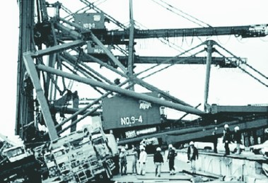 ] ]
|
| Figure 1: Collapsed cranes after the Kobe Earthquake [2] |
The Kobe earthquake of 1995, a near-field ground motion, has demonstrated that the seismic performance of gantry cranes is critical and cannot be omitted. During this earthquake, several cranes were gravely damaged in the steel structure (see Fig. 1), including a completely collapsed one [3,4]. This result showed that the damage to gantry crane structures was increased as a result of the high input energy induced by the near-field ground motions. They produce high velocity pulses causing increasing structural demands which may have detrimental influences on the gantry crane structures [5]. Hence, it is of great importance in the modern design of gantry cranes with better seismic-resistant behavior under near-field ground motions.
In literature, several researchers investigated the effects of near-field ground motion on engineering structures [6,7,8,9,10,11,12,13,14,15]. All the results from these studies show that the near-field ground motions play an essential role on the seismic response of various structures including bridges, buildings, tunnels, and power stations. However, there is only one research [16] focusing on the effects of near-field ground motion characteristics on the seismic response of gantry cranes.
To fully investigate the effects of near-field ground motions on gantry cranes, a comprehensive understanding of the structural characteristics of gantry cranes is indispensable. The ability to uplift, one of the most important features of gantry cranes, is proved to be critical to the seismic response [17,18,19]. Since gantry cranes are not fixed to the ground on which they sit. Instead, they sit on rails, which are embedded in the hard ground, with a set of wheels. Because this boundary arrangement does not provide positive vertical constraint, the wheels are free to uplift under sufficient loads theoretically. Thus, understanding the onset and effect of uplift is of much concern.
Some attempts have been made over the past decade on the seismic performance of crane structures. Originally, it was widely accepted that allowing uplift significantly reduces the resulting internal crane forces [20,21,22]. This assumption was tolerable since the early gantry cranes had small physical size and thus could tip at relatively small lateral loads. However, with constant growth in the physical size of new gantry cranes to achieve ever-larger lifting capacity, some opposite conclusions emerge [3,17] after the Kobe earthquake. These studies consider the uplift response as a potential threat to the structural safety of gantry cranes. While previous research focused predominantly on the response for several earthquakes and over varies excitation intensities in multiple directions [23,24,25,26,27], near-field ground motions were not particularly selected as seismic inputs and severe structural damage or collapse is omitted [18,28,29,30]. Given that, this paper evaluates the performance of gantry cranes allowing uplift and collapse subjected to near-field ground motions in multiple incident angles. In this way, we will have a more thorough understanding of how the uplift response influences the overall performance of gantry cranes.
This paper is organized to first give the reader information on the numerical model and nonlinear finite element model of a typical gantry crane with detailed modeling of boundary condition theoretically; then, in section 3, three near-field ground motions with exceeding probability of 2%, 10%, and 63% in 50 years respectively are chosen based on the site condition; there are four major issues discussed in section 4, the first two issues focus on the seismic response of the gantry crane under ground motions in the trolley-travel direction and cart-travel direction respectively. Then, the target responses of the gantry crane are compared between uplift-available and fixed boundary conditions. Finally, the probability of an uplift event is conducted by changing the seismic incident angle with an interval of 1 degree; additionally, the summary and conclusions are drawn based on the above sections in the last part.
2 Numerical model and uplift-available boundary condition
2.1 Finite element model

|
| Figure 2: Schematic of sample gantry crane |
|
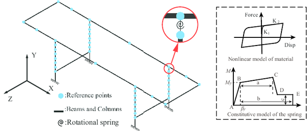
| Figure 3: 3D model of fixed gantry crane |
In the light of the structural data of the sample crane, the finite element model is developed in the OpenSees software [31], which considers the center-line approximation and omits the panel zone effect. This modeling approach is chosen as the extra flexibility introduced to the system due to the center-line dimension counterbalances the influence of panel-zone effect [18]. The P-Delta effect is employed to make allowance for the geometric nonlinearity [32,33]. Besides, the mass density, elastic modulus, yielding stress, and damping ratio are individually equal to 7800, 2.01Pa, 235 MPa, and 3% It should be noted that in this paper, the X, Y, and Z coordinates represent the trolley-travel direction, vertical direction, and cart-travel direction separately (Fig. 3).
In an attempt to replicate the nonlinear behavior of the sample crane more accurately, the junctions of trolley girders and legs are modeled as rotational springs [34]. Given that the trolley girder itself is a complete whole, only one rotational spring at the junction is needed. A schematic of the rotational spring model is shown in Fig. 3 and the constitutive model of the spring is also built where , and respectively. Since the trolley girders and legs are too long to ignore its nonlinear behavior during an earthquake, all of them are considered as bilinear kinematic hardening models [35,36]which are simulated by element in the OpenSees software (shown in Fig. 3).
2.2 Mechanism of uplift
|
|
| (a) Structure system on two-spring foundation | (b) Free body diagram of the system |
| Figure 4 | |
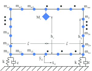
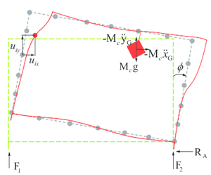
The system of the gantry crane under investigation is shown in fig. 4a. The superstructure consists of rigid masses and there are two degrees of freedom ( and ) per rigid mass as shown in Fig. 4. The steel structure is supported by a two-spring foundation with springs of stiffness and dashpots of constant , a distance from the center of the base. The system, initially at rest, is subjected to horizontal and vertical ground accelerations, and respectively. Using a force-based approach to model impact and friction, the equations of motion subjected to ground motions ( and ) can be written as:
|
|
(1) |
where are the acceleration, velocity and displacement vectors relative to the ground; represent the mass, damping coefficient and stiffness matrices of the system with respect to time; and mean the forces caused by ground motions, friction and impact respectively, all of which can be described as:
|
|
(2) |
|
|
(3) |
|
|
(4) |
where and are the rotation acceleration and rotation angle vectors of the structure in the plane of motion, illustrated in Fig. U; represents the vector of horizontal ground motion; means the friction coefficient of the ground and represents the vertical force of the structure foundation; It should be noted that the Kelvin model is utilized to simulate the impact effect after uplift, which uses a non-linear spring of stiffness (), the velocity and distance between the base and the structure foundation () and a damper coefficient (). Meanwhile, when , since no impact phenomenon occurs.
In Eq. (4), the damping coefficient can be related to the coefficient of restitution (), by equating the energy losses during impact (see Eq.(5) and Eq. (6)). Where roughly equals to the structural mass divided by the number of leg bases, and means the damping ratio. The specific values of these parameters are discussed detailedly in the next section.
|
|
(5) |
|
|
(6) |
Considering the structure system as a whole, the formulation can be described in full contact stage:
|
|
(7) |
|
|
(8) |
And the structure system after lift-off can be represented in the following mathematical models:
|
|
(9) |
|
|
(10) |
In these equations, , and represents the vertical acceleration, velocity and displacement of the center of mass; , and are column vectors, and is the height at which the center of mass is located. It is worth noting that although the concentrated mass points numbering are two dimensional, they are still organized in a vector mode. is the total mass of the structure system; means the total moment of inertia about the middle point of the base; and are the characteristic frequencies and ratios of critical damping during full contact for rocking and certical motions of the corresponding rigid superstructure, and are defined by the following equations:
|
|
(11) |
|
|
(12) |
|
|
(13) |
|
|
(14) |
2.3 Boundary condition
Since the cart wheels of the gantry crane are not firmly tied to the crane rails, it is achievable for the cart wheels to uplift from the rails due to an earthquake. Additionally, if a wheel uplifts more than the height of the wheel flange, it will fall off the track and cause considerable damage to the crane. Thus, a specialized boundary condition is desired to accurately simulate the significant seismic response.
There are three boundary modeling strategies which are used in correlational studies [37,38]. As shown in Fig. 5 and in order of increasing complexity, they are pinned, elastic-no-tension, and frictional contact. The first strategy is the simplest and most frequently used in the evaluation of the seismic performance of crane. When compressive vertical reactions are developed on the crane’s legs, the crane acts essentially pinned. However, this strategy will provide tensile reactions when the legs begin to leave the rails. This simulation is quite different from reality. Nevertheless, the pinned boundary cranes were also studied to compare with the uplift-available gantry cranes which will be discussed below.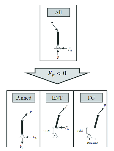
|
| Figure 5: Schematic showing behavior of three idealized boundary conditions |
The second strategy is called elastic-no-tension (ENT). Compressive vertical reactions will be developed under seismic excitation. But tensile vertical reactions will not be developed which is different from the pinned condition. Instead, the legs are allowed to uplift when the vertical reactions decrease to zero. However, the horizontal constraint will develop during uplift events which means derailment is not possible, so the legs move perfectly vertical [20]. This strategy is not recommended because of higher base shear demand compared with authentic uplift.
The third strategy is called frictional contact (FC) which is utilized in this paper since the strategy simulates the uplift response veritably. In this method, the horizontal constraint will vanish when there is no compressive vertical reaction based on the theory of Mohr-Coulomb friction (see Eq.(15)). In other words, the maximum horizontal force () is equal to friction coefficient () multiplied by the vertical force (). In this paper, is chosen as the value is proved to be generally effective in limiting premature sliding to a negligible range for the uplift-available gantry crane subjected to ground motions [2].
|
|
(15) |
To simulate the impact after uplift, a stiff spring in parallel with a damper should be added between the contact surface and the ground, which are used to achieve linear viscoelastic pounding behavior. The parameters were chosen as suggested by Muthukumar [39], which has been shown to be relatively insensitive to changes of an order of magnitude[40,41]. Therefore,in Eq.(6), the restitution coefficient is assumed . Besides, the stiff spring constant () is assumed to be based on the above researches. Since the friction contact boundary idealization can capture the critical uplift and derailment responses in a credible and simple way, the frictional contact model was utilized in the nonlinear dynamic time-history based analysis of the container crane.
| Step | Fixed(Hz) | Uplift(Hz) |
| 1 | 1.6196 | 0.4272 |
| 2 | 1.6862 | 0.4467 |
| 3 | 1.7471 | 0.6556 |
| 4 | 2.1726 | 1.5627 |
| 5 | 2.5582 | 2.4028 |
| 6 | 2.9681 | 2.4603 |
| 7 | 3.3210 | 2.5010 |
| 8 | 3.8397 | 2.0007 |
| 9 | 4.1226 | 3.0704 |
| 10 | 5.3055 | 3.6895 |
|
| Figure 6: Natural mode shapes for the four most interested modes of the uplift-available gantry crane |
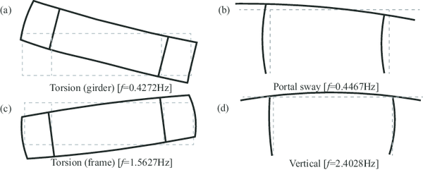
To obtain a more specific impressions, Fig. 6 sketches the values of the natural frequencies and mode shapes for the four most interested modes. These modes consist of two torsion modes, boom dominated (Fig. 6(a)) and frame dominated (Fig. 6(c)), the sway along the cart-travel direction (Fig. 6(b)), and a vertical displacement mode (Fig. 6(d)).
3 Selection of ground motions
The investigated gantry crane is located in the median area of Yunnan province, China. This is an earthquake prone area where multiple rare earthquakes have taken place in recent decades. Accordingly, the seismic capacity of the crane during an earthquake is of paramount importance. To fully investigate nonlinear behavior including the uplift phenomenon of the gantry crane, three rare earthquake waves with an exceeding probability of 63%, 10%, and 2% in 50 years respectively were chosen based on the site condition. Their peak ground accelerations are and and the specific curves are depicted in Fig. 5.
Fig. 7 shows the time-history curves and corresponding power spectra obtaining from fast Fourier transform of three seismic loads. Apparently, the dominant frequencies of all the three near-field ground motions drop in the scope of 0-1 Hz. Allowing for the uplift-available boundary condition decreasing the intrinsic dynamic stiffness of the gantry crane, the structure is more likely to resonate and therefore, cause greater distortion when subjecting to the near-field ground motions. In the light of Fig. 6, two out of four interested modes of uplift-available gantry crane are in the dominant frequency scope of these seismic waves while no mode is in 0-1 Hz of a fixed gantry crane.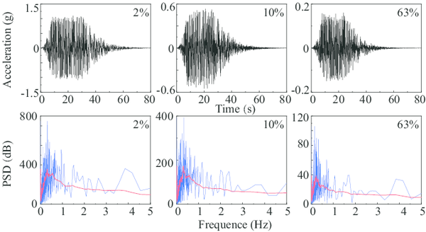
|
| Figure 7: time-history curves and corresponding power spectra of three seismic loads |
4 Results and Discussions
4.1 Seismic input in the trolley-travel direction
Considering the portal sway mode is the dominant response of gantry crane [18], the seismic inputs in the trolley-travel direction are investigated in the first place. Since the rare earthquakes are considered in this article, the vertical inputs should be investigated with the horizontal one concurrently and its magnitude is 0.65 times of horizontal acceleration magnitude in the light of specifications for seismic design of highway bridges in China [42]. The working conditions of the gantry crane are complex and the three most dangerous conditions, full-loaded trolley located on the midspan of the girders (Case 1), full-loaded trolley located on the cantilever end of flexible legs (Case 2), and rigid legs (Case 3), are studied in this paper.
| Direction | Ground motion | Midspan | Flexible Leg | Rigid Leg | ||
|
2% | |||||
| 10% | ||||||
| 63% | ||||||
|
2% | |||||
| 10% | ||||||
| 64% |
Note: means uplift event happens; means uplift event does not happen
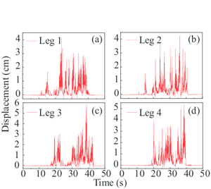
In general, nine separate analyses, three seismic waves combining with three working conditions, were carried out along with the trolley-travel direction in this section. Uplift events were observed in four cases of these analyses (Table. 2). Concretely, when the exceeding probability of the seismic input is 2%, all the three cases motivated the uplift of the legs. Inversely, the uplift event did not develop under the seismic input of 63% exceeding probability. As a contrast, the uplift event only happened in Case 3 when it comes to 10% exceeding probability.
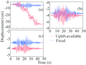
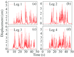
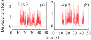
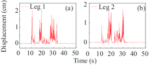
Given the responses of the gantry crane, the uplift events of the flexible legs and rigid legs were successively occurred (Fig. 8a). It is worth noting that in this paper, leg 1 and 2 represent two flexible legs while leg 3 and 4 represent corresponding rigid legs. As can be seen, the primary uplift displacements (more than 1 cm) of the leg 1 and 2 are at around 15th second. Simultaneously, the satisfactory result is at around 20th second with regard to the rigid legs. What’s more, the maximum uplift displacement of the flexible leg is approximately 38% less than that of the rigid leg.
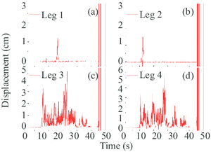
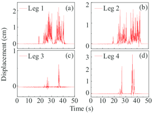
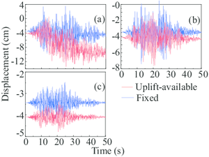
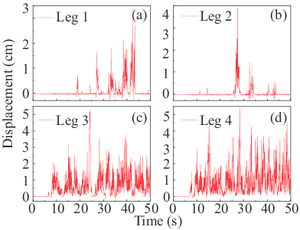
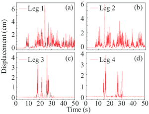
Comparing the displacement of the four legs of the gantry crane in Fig. 8a, the displacement curves show that the four legs experienced different uplift processes. This conclusion is not an individual phenomenon and can also be drawn from the analyses with the rest uplift event (also in Fig. 9a). It is remarkable since the gantry crane is symmetrical along the trolley-traveled direction and the mirrored legs will experience the same deformation when the legs are fixed on the ground. This phenomenon could be expounded that the uplift-available model has highly geometric nonlinear properties and therefore, causes the asymmetric seismic response of four leg bases.
In Fig. 8, the first uplift times of the two flexible legs are 22nd and 12th second separately and the time of the two rigid legs is 10th second. Apparently, the torsional deflection of the two flexible legs occurred during the ground earthquake motion. Since the full-loaded trolley lied on the cantilever end of the flexible legs, the rigid legs experienced more uplift processes compared with the flexible legs. Notice that the displacement results of all the four legs do not converge after 50 seconds which did not happen in the above case. A reasonable speculation is that the gantry crane collapsed under this situation and therefore, the non-convergence results of the specific structural dynamic equations were calculated.
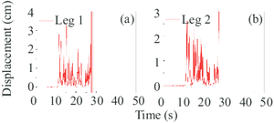
Different from the above two situations, the rigid legs did not uplift when the full-loaded trolley was located on the cantilever end of rigid legs under the 2% rare earthquake. Correspondingly, the two flexible legs experienced the first uplift response at about 12th second. Then, a series of uplift events took place with the input of the seismic wave. In the end, the gantry crane structure collapsed at about 27th second since the calculated results didn’t converge (see Fig. 9).
Remarkably, the gantry crane in Case 3 (the full-loaded trolley located on the cantilever end of rigid legs) also uplift under 10% rare earthquake (Fig. 9). As a contrast, Case 1 and Case 2 did not cause the uplift event of the gantry crane under the same ground motion. Since the full-loaded trolley lied on the cantilever end of the rigid legs under this situation, the flexible legs experienced more uplift processes compared with the rigid legs. As the intensity of the earthquake decreases, the structural strength of the gantry crane could resist the earthquake in Case 3.
4.2 Seismic inputs in the cart-travel direction
To fully investigate the uplift behavior of the gantry crane, the seismic inputs in the cart-travel direction are considered as well due to the relatively small span between two rigid legs in this direction. Again, the vertical inputs along with the horizontal components should be considered as well and the coefficient is 0.65. What’s more, the most dangerous working conditions, Case 1, Case 2, and Case 3, and three seismic inputs with 2%,10%, and 63% exceeding probabilities are also employed. That means nine separate analyses should be carried out along with the cart-travel direction in this section.
As shown in Table. 2, uplift events were observed in six cases of these analyses. Compared with the last section, four cases are the same and two added case is the gantry crane in Case 1and Case 2 with 10% seismic input. For convenience, uplift observed analyses in this part are named in sequence as Situation 1 to 6. The first four situations are one to one correspondence with the analyses in the last section and the fifth and sixth situation are the added cases (the gantry crane in Case 1 and Case 2 with 10% seismic input).
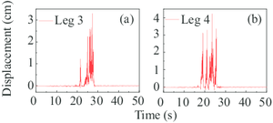
In Situation 1 to 4 (Fig. 13a-14a and 15), the uplift response is more obvious and the uplift period is much shorter compared with the corresponding analysis in section 1, which can be easily drawn by observing the figures. This phenomenon can be explained since the eigen period in the cart-travel direction is shorter than that in the trolley-travel direction. In most cases, the primary uplift events of all the four legs take place earlier than the corresponding analyses. It is worth noting that in this section, the collapse event of the gantry crane doesn’t appear while two collapse events are observed in section 4.1. To sum up, the seismic inputs in the cart-travel direction will cause more elastic deformations and uplift events. As a contrast, more plastic deformations are produced during the ground motion in the trolley-travel direction.
In Situation 5 and 6 (Fig. 14 and Fig. 15a), only the rigid legs experienced the uplift events and the vertical displacements were relatively small. Visibly, this fact can be explained by the conclusions drawn in the previous paragraph.
4.3 Comparison between uplift-available and fixed boundary conditions
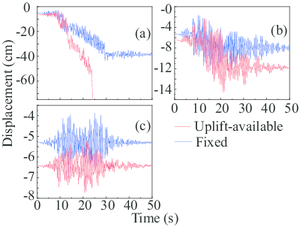
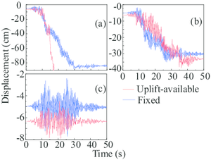
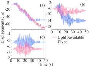
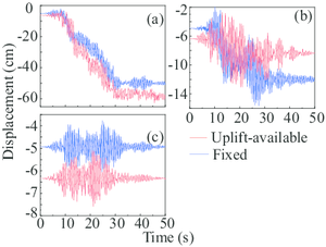
For a better understanding of the influence of the uplift-available boundary condition, the gantry crane with fixed boundary condition was investigated as a comparison in this section. Therefore, a total of 36 separate analyses were performed for two different boundary conditions. As representative examples, Figs. 10a and Fig. 10b depict the responses of the gantry crane in Case 1 experienced earthquakes of three different intensities. Notice that the vertical coordinate, displacement (cm), in these pictures represents the absolute deformation of the trolley halfway point.
| ground motion | Midspan | Flexible Leg | Rigid Leg | |||
|
2% | |||||
| 10% | ||||||
| 63% | ||||||
|
2% | |||||
| 10% | ||||||
| 64% |
Note: means uplift-available crane is in the ascendant; means fixed crane is in the ascendant
| Leg 1 | Leg 2 | Leg 3 | Leg 4 | |
| Case 1 | 13.61% | 13.33% | 15.56% | 13.61% |
| Case 2 | 0.00% | 0.00% | 13.06% | 13.06% |
| Case 3 | 71.67% | 70.00% | 1.39% | 1.67% |
|
|
| (a) Maximum vertical displacements of the rigid leg in Case 2 at different degrees. | (b) Maximum vertical displacements of the flexible leg in Case 3 at different degrees. |
| Figure 12 | |
These two special cases in Table 3 draw the opposite conclusion: the structural demand with a fixed boundary condition is larger than the uplift-available condition. Clearly, allowing this type of uplift greatly reduces the resulting internal crane forces, which echoes the assumption proposed by [43]. It is worth noting that the seismic inputs of the two cases are both in the cart-travel direction, where the structural eigen value is relatively small.
4.4 Influence of seismic incident angle
Concluding from the above research, the onset of uplift is sensitive to the direction of the seismic input. Therefore, to fully investigate the influence of seismic incident angle, further research focused on the uplift event and inelastic action is carried out in this section. Again, three working conditions, Case 1, Case 2, and Case 3, are considered with the 2% exceeding probability seismic input. Meanwhile, the interval of the seismic incident angle is 1 degree.
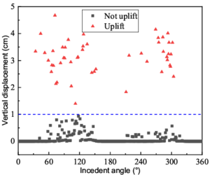
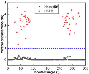
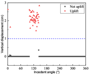
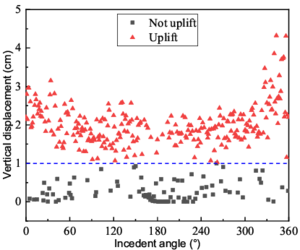
Table. 4 shows the uplift probability of flexible and rigid legs in three cases and the detailed information of four bold data are depicted in Fig. 11-12. As can be seen, the uplift probabilities are slightly different between two pairs of the legs, Leg 1 and 2, Leg 3 and 4. This phenomenon echoes the conclusion drawn in section 4.1 that the seismic response of the structure is not symmetrical along the geometric symmetry line. what's more, in Case 3, the flexible legs have maximum probabilities to uplift while in Case 2, the uplift event does not occur in the flexible legs.
Fig. 11 shows the maximum vertical displacements of the flexible and rigid legs in Case 1 at different degrees. To make a clear definition, only the maximum vertical displacement exceeding 1 cm is considered as an uplift event. Graphically, the red points signify the uplift event and black points represent no uplift event. In detail, the point graph is approximately symmetrical and the uplift points are concentrated in two intervals, from 30 degrees to 120 degrees and 240 degrees to 330 degrees (Fig. 11b). Remarkably, the uplifting probability is about 16% for the rigid leg which means the onset of inelastic action comes before the uplift event in most instances. Analogously, the uplifting probability is around 14% for the flexible leg (Fig. 11a).
The flexible leg has a higher chance, 72%, to uplift when the gantry crane is in Case 3 (Fig. 12). Convincingly, the wheel pressure of the flexible leg is small in this situation and therefore, it is easy to go to zero under a strong earthquake. Besides, the uplifting probability of the rigid leg in Case 2 is 13% and the uplift events gather from 100 degrees to 130 degrees.
The critical uplift response is sensitive to the seismic incident angle and the characteristics of uplift, both of which are captured well by the analytical models. A reasonable explanation of the four pictures is that the structure begins to absorb the seismic energy after reaching the plastic phase before it has time to get enough energy to uplift.
5 Conclusions
In this paper, three near-field ground motions with different exceeding probability are utilized to assess the uplift response of a typical gantry crane. Aiming to develop a thorough understanding of the uplift behavior of the gantry crane, a finite element model with the uplift-available legs is developed. Then, the two most dangerous incident angles of the structure are investigated with three different working conditions. Corresponding results of the uplift-available crane are compared with that of the gantry crane whose legs are fixed. Finally, whether the uplift event is prior to the inelastic deformation is also discussed. Several key findings are highlighted below:
- Uplift of a gantry crane may happen during a near-field ground motion whose exceeding probability is more than 10% And the direction of the ground motion has a significant influence on the seismic demand of the gantry crane. Therefore, predicting uplift is essential for properly designing and evaluating the seismic performance of gantry cranes;
- A detailed comparison between an uplift-available gantry crane and a fixed one is made in this paper. The uplift response of gantry cranes increases the seismic performance of the structure and even causes collapse during an earthquake. However, in rare cases, the opposite conclusion is drawn. That means the assumption, cranes performing well in an earthquake due to a rocking response, is partially true in certain cases;
- Uplift probability is introduced in this article to determine the prioritization of uplift event and inelastic response. With the change of seismic incident angle, the structure does not always uplift in all conditions. On the contrary, the inelastic response happens first in most situations and absorbs the seismic energy to prevent the occurrence of uplift events.
Acknowledgment
The research for this paper was supported partially by the Science and Technology Plan of Sichuan Science and Technology Department (No.2019YJ0243), National Science Foundation of China (No. 51675450 and No.51308465), and Postdoctoral Science Foundation of China (No.2015M580031). The authors would like to express their sincere gratitude to all the sponsors for financial support.
References
[1] Zhang, Z. W. Wang, J. N. Cheng, W. M. et al., The Manual of crane, Beijing: China Railway Publishing House, 2013.
[2] Jacobs, L. D. Kosbab, B. D. Leon,R. T. DesRoches, R. Seismic behavior of a jumbo container crane including uplift, Earthquake Spectra 27 (3):745–773, 2011.
[3] Kanayama, T. Large shaking table test of a container crane by strong ground excitation, ASME/JSME pvp1998.
[4] Chang, S. E. Disasters and transport systems: loss, recovery and competition at the port of kobe after the 1995 earthquake, Journal of Transport Geography 8 (1):53–65, 2000.
[5] Bilgin, H. Hysenlliu, M. Comparison of near and far-fault ground motion effects on low and mid-rise masonry buildings, Journal of Building Engineering 101248, 2020.
[6] Jia, H.-Y. Zhang, D.-Y. Zheng, S.-X. Xie, W.-C. Pandey, M. D. Local site effects on a high-pier railway bridge under tridirectional spatial excitations: nonstationary stochastic analysis, Soil Dynamics and Earthquake Engineering 52:55–69, 2013.
[7] Zhang, D. Y. Jia, H. Y. Zheng, S. X. Xie, W.-C. Pandey, M. D. A highly efficient and accurate stochastic seismic analysis approach for structures under tridirectional nonstationary multiple excitations, Computers & Structures 145:23–35, 2014.
[8] Jia, H.Y. Lan, X.L. Zheng, S.X. Li, L.P. Liu, C.Q. Assessment on required separation length between adjacent bridge segments to avoid pounding, Soil Dynamics and Earthquake Engineering 120:398–407, 2019.
[9] Günes, N. C. Z. Ulucan, Nonlinear dynamic response of a tall building to near-fault pulse-like ground motions, Bulletin of Earthquake Engineering 17 (6):2989–3013, 2019.
[10] Ma, H.B. Zhuo, W.D. Lavorato, D. Nuti, C. Fiorentino, G. Gu Y. , Briseghella, B. Probabilistic seismic response analysis on continuous bridges under near-fault ground motions, Iranian Journal of Science and Technology, Transactions of Civil Engineering 43 (3):491–500, 2019.
[11] Yang, F. Wang, G. Ding, Y. Damage demands evaluation of reinforced concrete frame structure subjected to near-fault seismic sequences, Natural Hazards 97 (2):841–860, 2019.
[12] Liu, Z. Li, X. Zhang, Z. Quantitative identification of near-fault ground motions based on ensemble empirical mode decomposition, KSCE Journal of Civil Engineering 24 (3):922–930, 2020.
[13] Xin, L. Yang, D. The cross-over frequency between pulse and high-frequency components of near-fault forward-directivity ground motions, Advances in Structural Engineering:1369433220911139, 2020.
[14] Falsone, G. Recupero, A. Spinella, N. Effects of near-fault earthquakes on existing bridge performances, Journal of Civil Structural Health Monitoring 10 (1):165–176, 2020.
[15] Sigursson, G. Rupakhety, R. Rahimi, S. Olafsson, S. Effect of pulse-like near-fault ground motions on utility-scale land-based wind turbines, Bulletin of Earthquake Engineering 18 (3):953–968, 2020.
[16] Peng, Q. Cheng, W. Jia, H. Guo, P. Fragility analysis of gantry crane subjected to near-field ground motions, Applied Sciences 10 (12):4219, 2020.
[17] Kanayama, T. Kashiwazaki, A. A study on the dynamic behavior of container cranes under strong earthquakes, Seismic Engineering, 1998.
[18] Kosbab, B. D. Seismic performance evaluation of port container cranes allowed to uplift, Ph.D. thesis, Georgia Institute of Technology, 2010.
[19] Zhe, L. I. Wang, G. X. Wang, D. Ji-Quan, H. U. Testing methods on dynamics behavior of jumbo container cranes under seismic loads, Journal of Wuhan University of Technology, 2013.
[20] Soderberg, E. Jordan, M. Dockside ship-to-shore cranes seismic risk and recommended design criteria, Liftech Consult Inc.: Oakland, CA, USA, 2007.
[21] Soderberg, E. Hsieh, J. Dix, A. Seismic guidelines for container cranes, in: TCLEE 2009: Lifeline Earthquake Engineering in a Multihazard Environment, pp. 1–11, 2009.
[22] Azeloglu, C. Sagirli, O. Edincliler, A. Mathematical modelling of the container cranes under seismic loading and proving by shake table, Nonlinear Dynamics 73 (1-2):143–154, 2013.
[23] Sagirli, A. Azeloglu, C. O. Guclu, R. Yazici, H. Self-tuning fuzzy logic control of crane structures against earthquake induced vibration, Nonlinear Dynamics 64 (4):375–384, 2011.
[24] Sagirli, A. Azeloglu, C. O. Investigation of the dynamic behaviors of cranes under seismic effects with theoretical and experimental study, Advanced Materials Research 445:6, 2012.
[25] Dong, D. Li, J. Teng, Y. Anti-seismic device design for container crane and its elastic-plastic time history analysis, Polish Maritime Research 22 :30–34, 2015.
[26] Jin, Y.L. Wu, T.X. Dynamic similarity analysis and experimental verification on a quayside container crane, Journal of Shanghai Jiaotong University 10, 2012.
[27] Otani, A. Nagashima, K. Suzuki, J. Vertical seismic response of overhead crane, Nuclear engineering and design 212 (1-3):211–220, 2002.
[28] Wang, D. Wang, G. Xiong, Y. Hu, J. Analysis of nonlinear dynamic second-order effect of a large-scale container crane under seismic excitations, in: Vibration Engineering and Technology of Machinery, Springer, pp. 889–899, 2015.
[29] Tran, Q. H. Huh, J. Nguyen, V. B. Haldar, A. Kang, C. Hwang, K. M. Comparative study of nonlinear static and time-history analyses of typical korean sts container cranes, Advances in Civil Engineering, 2018.
[30] Tran, Q. Huh, J. Nguyen, V. Kang, C. Ahn, J.H. Park, I.J. Sensitivity analysis for ship-to-shore container crane design, Applied Sciences 8 (9):1667, 2018.
[31] Mazzoni, S. McKenna, F. Scott, M. H. Fenves, G. L. et al., Opensees command language manual, Pacific Earthquake Engineering Research (PEER) Center 264, 2006.
[32] Gupta, A. Krawinkler, H. Dynamic p-delta effects for flexible inelastic steel structures, Journal of Structural Engineering 126 (1):145–154, 2000.
[33] Adam, C. Jäger, C. Seismic collapse capacity of basic inelastic structures vulnerable to the p-delta effect, Earthquake Engineering & Structural Dynamics 41 (4):775–793, 2012.
[34] FEMA 356: Prestandard and commentary for the seismic rehabilitation of buildings, 2000.
[35] AlBermani, F. Zhu, K. Nonlinear elastoplastic analysis of spatial structures under dynamic loading using kinematic hardening models, Engineering structures 18 (8):568–576, 1996.
[36] Imaoka, S. Chaboche nonlinear kinematic hardening model, ANSYS Release 12 (1), 2008.
[37] Kosbab, B. D. DesRoches, R. Leon, R. T. Seismic fragility of jumbo port container cranes in Ports, American Society of Civil Engineers, Jacksonville, Florida, United States, pp. 480–489, 2010.
[38] Huh, J. Nguyen, V. B. Tran, Q. H. Ahn, J.H.Kang, C. Effects of boundary condition models on the seismic responses of a container crane, Applied Sciences 9 (2):241, 2019.
[39] Muthukumar, S. DesRoches, R. A hertz contact model with non-linear damping for pounding simulation, Earthquake engineering & structural dynamics 35 (7):811–828, 2006.
[40] Anagnostopoulos, S. A. Pounding of buildings in series during earthquakes, Earthquake engineering & structural dynamics 16 (3):443–456, 1998.
[41] Maison, B. F. Kasai, K. Dynamics of pounding when two buildings collide, Earthquake engineering & structural dynamics 21 (9):771–786, 1992.
[42] GB02-2013, Specification of SeismicDesign for Highway Engineering, Industry Standards of the People’s Republic of China, 2014.
[43] MarCom, P. Seismic design guidelines for port structures, in: Working Group, no. 34, 2001.
Appendix. Pictures used in this paper
Document information
Published on 07/09/21
Accepted on 31/08/21
Submitted on 02/12/20
Volume 37, Issue 3, 2021
DOI: 10.23967/j.rimni.2021.09.003
Licence: CC BY-NC-SA license
Share this document
claim authorship
Are you one of the authors of this document?
