Abstract
Optimum implant positioning and technique used for its alignment are vital parameters to improve clinical results. Visual cues and jigs are utilized in the recent surgical techniques, which lead to some errors in the flexion-extension axis identification. Surgeons have used computer-assisted surgery for the alignment of the hip, knee, and shoulder. However, there is a restricted application of this technology to the elbow. In this study, a technique was used to model a drill guide template to precisely place an implant in the bone. The computed tomography dataset was used to construct four different elbow bones, and an elbow implant was modeled. The surgical drill guides were designed based on the computed tomography data. The drill guide templates and constructed bones were fabricated, using a 3D printer. The accuracy of the surgical guides was validated experimentally. The results showed that the mean deviations between the achieved and planned positions of the hole at the bone apex and base of bones were less than those reported in previous studies in both medial/lateral and posterior/anterior positions. The low positioning errors observed in this study proposed that the implant’s location can be precisely aligned to its target using the introduced technique.
Keywords: Elbow implant, Total elbow arthroplasty, Drill guide template, Rapid prototyping, 3D printing
1. Introduction
The elbow joint complex includes three bones, namely the proximal radius, distal humerus, and proximal ulna [1,2]. Commonly, the elbow is involved in many diseases, especially rheumatoid arthritis (RA) (20% to 60% of patients). Total Elbow Arthroplasty (TEA) is used to treat patients with diseases such as osteoarthritis, posttraumatic arthritis, rheumatoid arthritis (RA), and failed reconstructive procedures of the elbow [3,4,5,6]. Compared to the knee and hip joints, the size of the elbow is quite small. During the late 1970s and early 1980s, there were unsatisfactory results of TEA performed. Scientists have modified the implant design by achieving more knowledge about the biomechanics of the elbow. There are two types of elbow implants; linked and unlinked. These implants are comprised of humeral and ulnar components. The linked implants possess a hinge that links the ulnar and humeral components to prevent dislocation [4,7,8].
Implant loosening is the most prominent complication in the TEA. Periodical physical and radiographic evaluations are the only clinical methodologies to identify implant loosening [9]. Van der Lugt et al. (2010) used conventional standardized radiographs and evaluated the migration pattern of 18 elbow implants in 8 years. Two parameters were evaluated, including implant alignment and the presence of radiolucent lines. At the extended follow-up, increased and variable migration pattern was recorded for all humeral components [10]. One of the causes of loosening is an insufficient position of the articulating axis of the elbow implant. The implant malposition results in the excessive contact and stress concentration between the polyethylene bushings. Ideally, the natural motion of the elbow joint is reproduced by the implant after TEAs. Hence, the implant flexion-extension axis must be similar to the native joint [11,12].
Critical parameters, such as implant positioning are dependent on the applied alignment technique. Sufficient placement of the implant is an essential parameter for optimal durability and functionality of the device in TEA operation. Biomechanical and anatomic considerations should be utilized for the positioning of the implant. An implant that is optimally implanted should imitate the normal motion to reduce the risk of loosening [13]. Even a small malposition of the components can cause loosening, early wear, and poor function [14,15]. Jigs and visual cues are used in recent surgical techniques for TEA and estimation of the native flexion-extension axis of the elbow. Geometric centers within the capitellum and trochlea assist in determining the flexion-extension [16,17]. Some deviations and errors of up to 10° may happen during the flexion-extension axis identification. Modern implants have improved the survival rates, however, loosening is still the main problem [18,19]. Therefore, both surgical technique and implant design should be improved to attain better results.
Computer-assisted surgery has proved a valuable outcome in surgical disciplines. Surgical guides have been used to enhance the accuracy of implant placement [20,21]. The ability of surgeons to place an implant accurately is increased through surgical methods that are assisted by the computer. It has been reported that using computer-aided methods improves implant alignment in comparison to conventional techniques [19]. Determining the rotation axes of the elbow before and after the surgery can demonstrate the critical role of implant location in terms of loosening. There is a potential for computer-assisted surgery (CAS) to be an excellent assistant to invasive surgery in various orthopedic areas [22,23,24]. A large number of reasons such as implant malalignment may reduce component loosening. Since there is no potential for controlling and limiting the patient’s daily activities after the operation, there should be true component positioning to prevent loosening.
Compared to the arthroplasty of the hip and knee, the elbow implant is less successful. Misalignment of components may be the reason. Previous studies had demonstrated the reliability and accuracy of computed tomography (CT) scanning and rapid prototyping (RP) techniques such as 3D printing [25,26,27,28]. The scarcity of elbow replacements compared to that of the hip and knee has deterred researchers from making statistical correlations between clinical outcomes and implant alignment. Therefore, very little is known about the computer-aided design (CAD) and computer-aided manufacturing (CAM) surgical guide for the elbow joint. This is a call for further studies and investigations. In this study, the model of humerus bones was constructed from a CT dataset.
A linked elbow implant was modeled, using CAD and computer-aided engineering (CAE) software packages. The surgical guides were designed based on a patient’s CT dataset, using an image processing software. Furthermore, a surgical drill guide was developed to lead drilling in the proper direction. The modeled implant was placed in the bones, using surgical guides in the image processing software. The constructed bones and surgical guides were fabricated, using a 3D printer. Experimental validation was carried out to determine the precision of the surgical guide for surgery. It was hypothesized that the introduced technique using CAD and 3D printing for humeral implant positioning would lead to greatly precise positioning.
2. Materials and methods
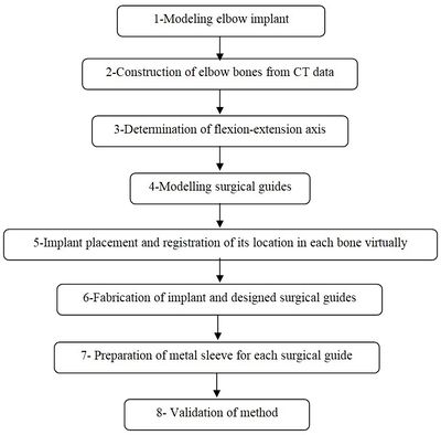
A CT-based model allows accurate placement of an implant, resulting in the inserting of the implant in the most strategically valid locations, using 3D virtual analysis prior to the operation. Virtual implant planning is driven by the successive production of surgical guides and restorative considerations. The fabrication process of a surgical guide starts from the diagnostic anatomy positioning. The surgical guide is comprised of guide holes to lead the drilling sequence. Figure 1 shows the process of preparing the surgical guide. Firstly, a linked elbow implant was modeled by using CAD software. Secondly, humerus bones were constructed via Mimics software (Materialise NV., Belgium). Thirdly, the flexion-extension axis of each humerus bone was identified in the Mimics software. Fourthly, the surgical guide and drill guide were modeled for each humerus bone. The CAD model of drill guide templates was developed by considering the bone anatomy. Next, in the fifth step, the implant was placed in the constructed bones. The placement of the modeled implant was performed through the designed surgical guides by using the Mimics software. In the sixth step, models of the surgical guides and bones were fabricated for validation by using the RP technology. In the seventh step, a proper metal sleeve that considered the diameter of the drill guide was prepared for each surgical guide. Finally, in the last step, the implant was inserted in each bone by using the designed surgical guide experimentally and the results were validated.
|
| Figure 1. The preparation process of the elbow surgical guide |
2.1 Modeling elbow implant
Coonrad-Morrey (Zimmer, Warsaw, IN) is one of the most commonly used linked elbow implants. Therefore, this implant was modeled in this study. A caliper is used to obtain the dimensions. The axis of the humeral component is perpendicular to the long axis of the stem [4,7]. The humeral component was modeled, using Solidworks (Dassault Systèmes, USA) software (Figure 12).

|
| Figure 2. (a) Coonrad Morrey elbow implant. (b) Modeled the humeral component of the Coonrad-Morrey implant |
2.2 Construction of elbow bone
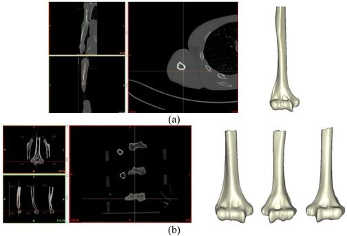
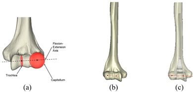
The Mimics software was used for the construction of elbow bones. Four different models of humerus bones were constructed with varied sizes. One of the models was constructed from CT data with a resolution of 0.477 mm and a slice thickness of 0.7 mm. The other three models were constructed from CT data with a resolution of 0.625 mm and a slice thickness of 2.5 mm (Figure 3 ). The flexion-extension axis is oriented along a line through the anteroinferior aspect of the medial epicondyle (or the rotation center of the greater sigmoid notch) and projected center of the capitellum [16,17]. Figure 4 shows the determination of the flexion-extension axis on the constructed bone in Mimics software. Thereafter, the modeled implant was inserted strategically into the humerus bones.
|
| Figure 3. Constructed humerus bones from CT data. (a) Resolution of 0.477 mm. (b) Resolution of 0.625 mm |
|
| Figure 4. (a) The anatomic flexion-extension axis of distal humerus. (b) Flexion-extension axis (c) transparent view of the implanted bones |
2.3 Modeling of surgical guide template
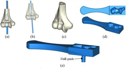
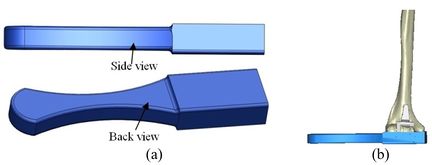
A rectangular mold was developed as a drill guide template using Mimics software. Then, the surgical guide was fitted on the first implanted humerus bone (Figure 5). The surgical guide needs to accurately seat on the distal of the humerus bone. The humerus bone was cut for further realization of the method. The modeled implant was inserted into the humerus bone based on the flexion-extension axis. A hole was made based on the position of the implant stem in the bone. In order to do it, a bar (with a similar dimension to the implant stem) was precisely fitted on the stem of the implant stem (Figure 6). A hole created by the bar had a diameter of 5 mm. The surgical guide was designed based on the shape of the distal region. Then, a hole was made in the surgical guide based on the direction and position of the implant stem. Finally, to lead the drill in the right direction, a drill guide was designed based on the position and direction of the hole in the bone. The same procedure was performed on all humerus bones.
|
| Figure 5. (a) Modeled surgical guide. (b) Surgical guide fitted on the implanted bone |
2.4 Fabrication and metal sleeve preparation
Surgical guides and humerus bones were fabricated, using a 3D printer (Dimension elite, Stratasys, USA) technique (Figure 7). CAD files of humerus bones and the surgical guides, in STL format, were transferred to the 3D printer. A metallic sleeve was fixed inside the hole of the surgical guide that guides the drill to accommodate the passage of the drill precisely. A standard tube (Ekinciler Iron and Steel IND. INC, Istanbul, Turkey) with an internal diameter of 5.2 mm and an external diameter of 5.5 mm was provided for the metal sleeve. As the internal diameter of the sleeve should be 0.2 mm bigger than the diameter of the drill [29,30], a sleeve with a 5.2 mm internal diameter was used for a 5 mm surgical drill. The tube was cut into 5 mm length, using a saw. A super glue (UHU, UHU GmbH & Co. KG, Germany) was used to fix the metallic sleeve firmly inside the drill guide.

|
| Figure 7. (a) Fabricated surgical guide. (b) Metalic standard tube. (c) Fabricated surgical guide |
The position of the holes was measured in the Mimics software to validate the accuracy of the method. A power drill with a 5.0 diameter drill bit was used to make a hole in the bones (Figure 8). A F-clamp was used to fix the bones, then, the surgical guides were set on the bones precisely. Since the surgical guides were designed based on the shape of the bones, they were mounted on the bone smoothly and without any movement to the sides. Consequently, the bones were drilled using a drill machine. A caliper was used to measure the position of the planned and achieved holes in the bones. The positions of the tip and base of the bone are as follows:
- -Base-distance: Diversity in distances at the implanted bone shoulder in the direction of medial/lateral and posterior/anterior.
- -Tip-distance: Diversity in distances at the implanted bone apex in the direction of medial/lateral and posterior/anterior.

|
| Figure 8. The sequence of making a hole in bones using surgical guide template |
3. Results
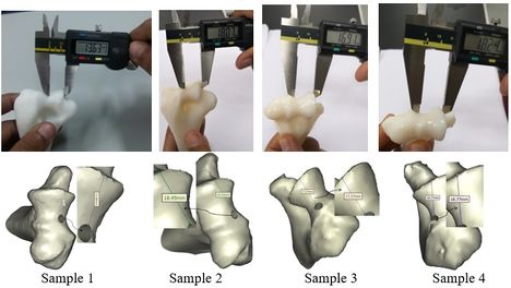
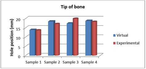
Figures 9 and 10 show the achieved and planned positions of the hole at the bone apex in the medial/lateral direction. On one side, the Mimics software package was used to make a hole and on the other side, similar holes were made experimentally, using the surgical guide template. Virtually, the positions of the holes were measured at 13.88 mm, 18.45 mm, 17.37 mm, and 18.77 for Sample 1, 2, 3, and 4 in the medial/lateral direction, respectively. Experimentally, the positions of the holes were measured at 13.63 mm, 18.07 mm, 16.91 mm, and 18.24 for Samples 1, 2, 3, and 4, respectively, in the same direction.
|
| Figure 9. Position of planned and achieved holes at the tip of bone in medial/lateral direction |
|
| Figure 10. Position of planned and achieved holes at the bone apex in the medial/lateral direction |
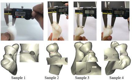
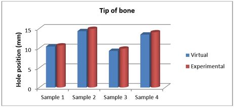
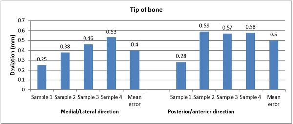
Figures 11 and 12 present the achieved and planned positions of the hole at the bone apex in the posterior/anterior direction. Virtually, the positions of the holes were measured at 10.70 mm (Sample 1), 14.91 mm (Sample 2), 9.88 mm (Sample 3), and 14.04 (Sample 4) in the posterior/anterior direction. Experimentally, the positions of the holes were measured at 10.42 mm, 14.32 mm, 9.31 mm, and 13.46 for Sample 1, 2, 3, and 4 respectively. The deviations (errors) between the achieved and planned holes at the bone apex were seen at 0.28 mm, 0.59 mm, 0.57 mm, and 0.58 mm for samples 1, 2, 3, and 4 respectively in the posterior/anterior direction. However, the deviations in the medial/lateral direction were 0.25 mm, 0.38 mm, 0.46 mm, and 0.53 mm for samples 1, 2, 3, and 4 respectively (Figure 13).
|
| Figure 11. Planned and achieved holes at the tip of bone in posterior/anterior direction |
|
| Figure 12. Position of planned and achieved hole at the bone apex in the posterior/anterior |
|
| Figure 13. Deviations (errors) between planned and achieved holes at the bone apex in medial/lateral and posterior/anterior directions |
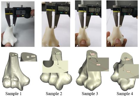
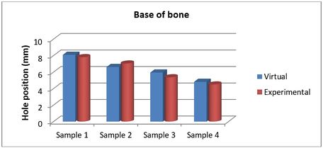
The achieved and planned positions of the holes at the base of the bone in the medial/lateral direction are shown in Figures 14 and 15. The positions of the holes (experimentally) were measured at 7.81 mm, 7.04 mm, 5.37 mm, and 4.50 mm for Samples 1, 2, 3, and 4 respectively. Virtually, the positions of the holes for samples 1, 2, 3, and 4 were measured at 8.10 mm, 6.62 mm, 5.95 mm, and 4.82 mm in the same direction, respectively.
|
| Figure 14. Planned and achieved hole at the base of the bone in the medial/lateral direction |
|
| Figure 15. Position of planned and achieved holes at the base of the bone in the medial/lateral direction |
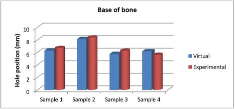
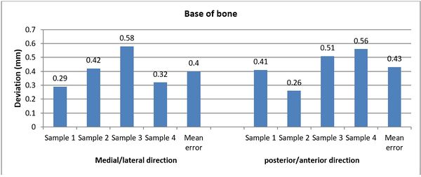
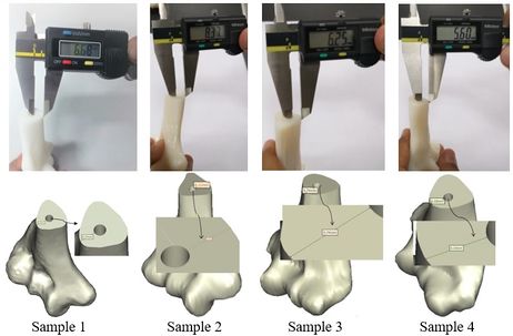
The achieved and planned positions of the holes at the base of the bone in the posterior/anterior direction are shown in Figures 16 and 17. Virtually, the positions of the holes for Samples 1, 2, 3, and 4 were measured at 6.27 mm, 8.11 mm, 5.74 mm, and 6.16 mm, respectively. Experimentally, the positions of the holes were measured at 6.68 mm, 8.37 mm, 6.25 mm, and 5.60 mm for Samples 1, 2, 3, and 4, respectively. In the posterior/anterior direction, the deviations at the base of bones were 0.41 mm (Sample 1), 0.26 mm (Sample 2), 0.51 mm (Sample 3), and 0.56 mm (Sample 4) (Figure 18). However, the deviations were 0.29 mm, 0.42 mm, 0.58 mm, and 0.32 mm for Samples 1, 2, 3, and 4 respectively, in the medial/lateral direction.
|
| Figure 16. Planned and achieved holes at the base of the bone in the posterior/anterior direction |
Document information
Published on 12/01/21
Accepted on 11/10/20
Submitted on 21/07/20
Volume 37, Issue 1, 2021
DOI: 10.23967/j.rimni.2020.10.006
Licence: CC BY-NC-SA license
Share this document
Keywords
claim authorship
Are you one of the authors of this document?
