Abstract
Piezoelectric Macro-Fiber Composite (MFC) utilization is increasing in engineering fields due to its strong actuation forces and high flexibility. In this paper, piezoelectric () type (M8528-P1) patches are applied for active control of a cantilever composite beam. A linear coupled finite element model for piezoelectric MFC actuation of the composite beam was developed based on the APDL-ANSYS codes by using linear piezoelectric constitutive equations to study smart composite beam behavior in open and closed-loop cases. Active vibration control response of laminated composite beams with various stacking sequence configurations was examined, and the results were compared. In this, the proportional type (kp) of control algorithms is utilized, and in the summary of work refined two sets of finite element models. The first set their laminates to have an orientation (0 with 90), and others have an orientation (0 with 45). When the control signal applied with the gain (kp) to a system increases, the rise time generally decreases, the actuator voltages for different control gain for all cases are observed with the increase in the proportional constant. The findings of this study indicate that the composite beams composed from (0/90)stacking sequence sets had reached stability state faster than the composite beams composed from (0/45) stacking sequence sets.
Keywords: MFC piezoelectric, smart composite beam, FEM (APDL Codes), active vibration
1. Introduction
Vibration is present in countless daily life applications, and more often, vibration is highly undesirable. Undesirable vibration may decrease the performance of the product and cause safety or economic issues [1]. Vibration damping includes active, passive, and hybrid damping techniques. It is important to understand that passive damping can be very efficient in damping out high-frequency excitation, while active damping can be used to control low-frequency vibrations [2]. Active vibration-reducing techniques turn out to be a reality for a wide variety of applications [3]. An active method integrates sensors and actuators with a flexible structure, operated by a control scheme. An essential issue in active control systems is sensor and actuator selection [4]. The ever-increasing use of smart composite materials in advanced areas such as aerospace, automotive, and sports equipment has motivated researchers to explore behavior and performance characteristics [5].
There are some previous studies reported in this work. The simple cantilever beams active vibration control is investigated in [6-10]. Piezoelectric patches are mounted on the beams as actuators. With the purpose of sensing the vibration level, a strain-gage or another piezoelectric patch can be used. The identification system and placement control technique was utilized in [6]. The piezo patches and beam structure’s finite element model is constructed, and the closed-loop control is applied in [7,8]. Also, Singh et al. [9] utilized the model of the beam and piezo-patches finite element; however, modal control techniques were employed. Xu and Koko [10] used the commercial finite element package ANSYS to state the findings. The control design was conducted in the space state that was set in the analysis of the finite element model. For the control design, MATLAB as a system toolbox was utilized in their experiment. The sensors/actuators influence site was investigated. It was noticed that the site near the fixed end for the vibration control was better. Lim investigated several modes for vibration control of a fixed square plate by using devices of location discrete sensor/actuator at maximum strain points [11]. Quek et al. introduced a typical placement method of pairs of piezoelectric sensor /actuator for the vibration control sealed compound plates [12]. Xiamin et al. used four-bar linkage to investigate active vibration control [13]. The model of the finite element is applied and the reduced mode, robust , and standard H∞ control methods are analyzed. Halim and Moheimani investigated a set of proposals to a criterion for ideal placement of a collected piezoelectric sensor-actuator pair on their supported plate by using modal and locative controllability [14]. Bendine et al. studied the modeling of the active vibration control of a smart functionally graded (FGM) beam based on a higher-order shear deformation theory [15]. The locations of piezoelectric actuators and sensors have a great influence on the reliability and control system efficiency. Malgaca studied optimal parameters with respect to positive position feedback used in the real-time control algorithm determined with the objective functions [16]. Flexible single-link composite manipulator with [45/-45] and [0/90] lay-ups are performed to reduce endpoint vibrations. Takacs and Rohal-Ilkiv [17] proposed a direct closed-loop prototype method in the active vibration control system modeled in the finite element method using APDL language for the clamped-free aluminum beam piezoelectric actuation using a linear quadratic controller (LQ) with a Kalman-filter. Vashist and Chhabra [18] found the optimal piezoelectric actuator’s locations by using an integer coded genetic algorithm GA on their plate where the singular value decomposition’s control matrix was used as a fitness function. Similar results of the frequency responses between experimental and Finite Element Method were found. Yavuz et al. analyzed a system of active vibration control’s closed-loop with the purpose of suppressing the vibrations of the end-point [19]. They established the system’s mathematical model by using the Lagrange equations. The digital solution is achieved through mixing the Newmark technique with the control action. They applied PID control action with the purpose of finding the value of the actuator signal at the appropriate time. Liu X. et al. studied the piezoelectric actuators’ placement optimization and the membrane structure’s active vibration control [20]. They designed the classical linear quadratic regulator controllers with the aim of suppressing the undesired vibration. Simulation findings indicated that the piezoelectric actuators’ optimal locations are influenced by the actuator’s additional mass and stiffness. Van et al. developed a finite element model according to the theory of first-order shear deformation for active vibration control and optimal placement of laminated composite plates with linked pairs of distributed piezoelectric sensor/actuator [21]. Baghaee et al. developed the aero elastic panel flutter of the laminate composite plate to include two piezoelectric (MFC-type) [22]. They determined MFC actuator’s input voltage through the velocity or proportional feedback control algorithms according to the sensor output. Usman et al. used piezoelectric MFC energy harvesting on the cantilever beam connected to a downstream cylinder and placed stationary upstream cylinder before applying wind flow on both cylinders [23]. Optimum spacing between two cylinders was identified as being three times the circular cylinder diameter. Heganna and Joglekar [24] studied the forced vibration control analysis of the beam structure experimentally. The smart structure considered finite and flat cantilever beam-like fiber structure with piezoelectric PZT patches attached on the surface.They also analyzed the vibration control effect of adjusting the location of PZT patches. Xie et al. proposed the fractional-order PD algorithm on the active vibration control of a lattice grid beam [25]. The vibration responses and dynamic model was based on the third-order shear deformation theory. A new active vibration control method is implemented using the PD algorithm in fractional order. Rimašauskienė et al. developed and experimentally analyzed the passive and active vibration control techniques for a thin-walled composite beam [26]. After the experiments with active vibration control, it was noticed that the vibration damping of the analyzed system was far higher at its resonant frequency in all cases. However, it could be inferred from the experimental results that passive and active vibration control systems were effective for thin-walled composite beam vibration amplitude control.
This work deals with the active vibration control analysis in smart composite beam structures by using ANSYS APDL codes. All nodes in the composite structure beam are subjected to the boundary condition (exactly 1260 boundary condition), and different proportional control gain is used to control vibration suppression to two sets of the composite beams, (0/90) sets and (0/45) sets, to reach the steady-state. From the obtained results, it can be concluded that the technique is able to dump the vibration of the composite beam structure.
2. Piezoelectric constitutive equations
Under the influence of stresses and voltage, the magnitude of the strain result and amount of electric charge accumulated by piezoelectric material specifies the actuation and sensing characteristics of these materials. Both constituent relationships under a piezoelectric material may be used to quantify these properties. Macroscopically, the piezoelectric materials display a field–strain relation [27]. The relationship is almost linear for the low electrical field, which can provide many advantages when using piezoelectric materials for system modeling and control. Nevertheless, the polarization saturates in a high electrical field, and domains extend and switch. This induces significant non-linear behavior that may be detrimental to the use of piezoelectric materials In the control implementation associated with a high electrical field [28]. In several applications of piezoelectric materials to continuous structures, the linear behavior is adopted despite the nonlinear behavior at a high electric field. The direct and converse effect of the piezoelectric phenomena involves an interaction between the mechanical behaviors of a material; Linear constitutive equations contain two mechanical variables and two electrical variables [27]. The equations governing the direct and converse piezoelectric effect in the matrix form are expressed respectively as
|
|
(1) |
|
|
(2) |
where is the electric displacement, is the transpose of the dielectric permittivity matrix , is the mechanical strain vector, is the dielectric permittivity matrix at constant mechanical strain, is the electric intensity vector, is the mechanical stress vector and is the matrix of elastic stiffness at constant electric field strength. The same relationship can be written in three other forms, depending on which variables are chosen to be independent. The direct relationship given by Eq.1 is normally used when modeling the sensing capability of the piezoelectric material, while the actuator capability is modeled using the converse effect relationship given by Eq. (2) [29].
3. Simulation method
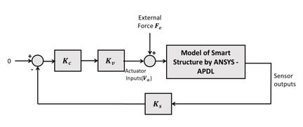
In this section, ANSYS software simulates active vibration control in the smart composite. Figure 1 shows the block diagram of the obtained analysis. ANSYS/Multiphysics and ANSYS/Mechanical programs can be used for modeling structural fields with piezoelectric smart patches, whereas is the force of vibration generated. The instant value of vibration producing force can be described at each time step. In the analysis below, it is taken as at and zero for other time steps. At a piezoelectric sensor location, the strain () is calculated. Reference input for vibration cancellation is zero. , , and are respectively, the variables the control, power, and sensor amplification factors. is taken as 200, and is changed in the analysis below. Only the proportional control is applied. The proportional constant for the actuator voltage was obtained from the multiplication of . Therefore, the results are not affected by changing the values of , and and keeping their multiplication the same. To evaluate the performance of the vibration control, the calculated deflection at a location, , is observed.
|
| Figure 1. Block diagram of the analysis |
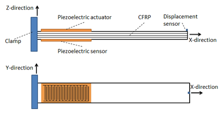
First, the structures of the beam type are considered. The configuration of the beam composite structure is shown in Figure 2.
|
| Figure 2. Configuration for the structure of the beam type |
3.1 Material Properties
Finite Element Analysis is used as the numerical modeling tool to simulate the dynamic characteristics of the composite structures by ANSYS macro codes, and the macro file has been written by using APDL. The first step in the coding process defined model geometry by using direct mesh generation of smart structure. In first our system, we used a composite smart beam of size (400 mm 28 mm ) and various thickness (1.59 mm, 2.12mm and 3.18mm) according to number of laminates, with () piezoelectric patch actuator type (M8528-P1). These typically consist of an active area (85mm 28 mm) with (0.3 mm) thickness, and it is embedded on the beam from (10 mm) on the fixed point, as shown in Table 1 for all cases.
3.2 Simulation procedures
In the first step, the beam structures type is taken and considered. Figure 2 displays the configuration of the structure with sensor locations. The displacement value is taken from the displacement sensor, and similarly, the strain value is taken from the strain sensor as the feedback. Here, the product of ANSYS /Multiphysics (version 18) was applied to the structures of the smart composites model. The combination of the ANSYS modeling and solution into the control action codes were achieved by ANSYS [30].
The composite smart structure beam is studied, as indicated in Table 1.
| Table 1 Dimensions and distances of Composite beam structure | ||
| Case No. | Composite layers | Dimensions of the structure (mm) |
| 1 | (0/90/0) | 400x28x1.59 |
| 2 | (0/90/0/90) | 400x28x2.12 |
| 3 | (0/90/90/0) | 400x28x2.12 |
| 4 | (0/90/0/0/90/0) | 400x28x3.18 |
| 5 | (0/45/0) | 400x28x1.59 |
| 6 | (0/45/0/45) | 400x28x2.12 |
| 7 | (0/45/45/0) | 400x28x2.12 |
| 8 | (0/45/0/0/45/0) | 400x28x3.18 |
The macro file creates nodes and finite elements to the structure. In the first part, composite materials have used element type SOLID185 layered structural elements for composite beam or plate part, and element type (SOLID5) elements with (MASS21) were used in the second structure part for the piezoelectric part in the structure [31]. Overall, these macro codes as shown in Table 2 indicate the defined element types of various materials.
| Table 2 Element definition codes | |
| /PREP7 | ! start the preprocessing |
| ! Define Element type #1 | |
| ET,1,185 | ! chooses SOLID185 element for analysis composite material |
| KEYOPT,1,3,1 | ! Key option #3 = 1 LAYERED SOLID ELEMENTS |
| KEYOPT,1,2,2 | ! Key option #2 = 2 ENHANCED STRAIN FORMULATION |
| KEYOPT,1,8,1 | ! Key option #8 = 1 STORE DATA FOR ALL LAYERS |
| ! Define Element type #2 | |
| ET,2,solid5,3 | ! chooses SOLID5 element for analysis piezoelectric material |
| ET,3,mass21 | |
Therefore, an essential next step to confirming in three-dimensional composite material properties is assigned. As shown in Fig. 2, the structure is divided into two parts. The first part deals with composite material, and the other part is actuator and all properties, as shown in Table 3, and all that has been gained from [32][33]&[34].
| Table 3 Material properties of MFC and CFRP | ||||
| Material Properties | CFRP | MFC | ||
| Young’s modulus | 30.34 GPa | |||
| Young’s modulus | 15.86 GPa | |||
| Young’s modulus | 9.03 GPa | |||
| Shear modulus | 5.52 GPa | |||
| Poisson’s ratio | 0.31 | |||
| Poisson’s ratio | 0.30 | |||
| Density ρ | 5020 | |||
| Piezoelectric Stress constant ( ) | -3.47 | |||
| Piezoelectric Stress constant ( ) | 12.36 | |||
The ANSYS macro of the material properties is given in Table 4. The first material is represented by composite material (Carbon fiber reinforced polymer), and the second material is represented by the piezoelectric (MFC) actuator material.
| Table 4 Composite material properties codes | |||
| /PREP7
MP,EX,1,140E9 |
! Define Material 1# : E1= | ||
| MP,EY,1,8.75E9 | ! Define Material 1# : E2= | ||
| MP,EZ,1,8.75E9 | ! Define Material 1# : EZ=EY ; E3= | ||
| MP,GXY,1,7.2E9 | ! Define Material 1# : shear modulus xy-plane | ||
| MP,GYZ,1,6.21E9 | ! Define Material 1# : shear modulus xz-plane | ||
| MP,GXZ,1,7.2E9 | ! Define Material 1# : shear modulus yz-plane | ||
| MP,PRXY,1,0.3 | ! Define Material 1# : Poisson coefficient | ||
| MP,PRYZ,1,0.3 | ! Define Material 1# : Poisson coefficient | ||
| MP,PRXZ,1,0.3 | ! Define Material 1# : Poisson coefficient | ||
| MP,DENS,1,1550 | ! Define Material 1# : Density for composite material |
The number of composite layers, the thickness of layers, and orientation angles of fibers are assigned as macro APDL ANSYS codes for the first material, as given below in Table 5.
| Table 5 Orientation angles’ Composite layers codes | |
| SECTYPE,1,SHELL | set #1, [0/90/0] |
| SECDATA,0.53e-3,1,0 | ! 1st LAYER 1: Thk=0.53e-3m, THETA = 0 |
| SECDATA,0.53e-3,1,90 | ! 2nd LAYER 2: Thk=0.53e-3m, THETA = 90 |
| SECDATA,0.53e-3,1,0 | ! 3rd LAYER 4: Thk=0.53e-3m, THETA = 0 |
The second material piezoelectric actuator properties are given in Table 6 as macro ANSYS.
| Table 6 MFC properties codes | |
| ! Define dielectric constant | |
| MP,DENS,3,5020 | ! Density for MFC piezoelectric material |
| MP,PERX,3,15.586E-9 | ! Permittivity in X direction |
| MP,PERY,3,15.586E-9 | ! Permittivity in Y direction |
| MP,PERZ,3,11.79E-9 | ! Permittivity in Z direction |
| TB,PIEZ,3 | ! Define piezoelectric table |
| TBDATA,16,0 | ! e16 piezoelectric constant |
| TBDATA,14,0 | ! e25 piezoelectric constant |
| TBDATA,6,-3.47 | ! e32 piezoelectric constant |
| TBDATA,9,12.36 | ! e33 piezoelectric constant |
| TB,ANEL,3 | ! Define structural table |
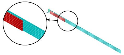
After all dimensions and properties of both composite and piezoelectric properties are defined, the type of element is assigned for each type of material. SOLID185 layered structural elements are assigned for the composite part, and SOLID5 elements are used for the piezoelectric part of the structure. Then, the static solution is analyzed to evaluate the initial deflections of each node and element. The model is discretized into finite elements model, as shown in Fig. 3.
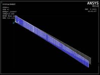
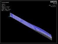
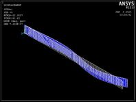
The first three mode shapes and natural frequencies of the composite plates were obtained using APDL ANSYS macro codes. The obtained results were shown in Fig. 4. The first three natural frequencies evaluated by the modal shape analysis method using ANSYS (15.665 Hz), (94.17Hz), and (161.63Hz), respectively, for the first case considered in the present study, are shown in Fig. 4.
Fixed boundary conditions are described for the nodes and given in Table 7 as macro ANSYS.
| Table 7 Boundary conditions of composite beam codes | |
| CP,1,volt,all | ! set #1 of coupled degrees of freedom. |
The degrees of freedom of the top and bottom surfaces for piezo actuator and sensor are coupled simultaneously with volt by APDL ANSYS “CP” command. Modal analysis was performed to determine parameters from vibration data measures like the inherent dynamic characteristics of the system in forms of natural frequencies, mode shapes and damping factor, and so to determine time step [35].
|
| Fig. 3 Finite element model |
Householder method (reduced method) can be used for the beam structures which have the solid coupled field in ANSYS. The time step is the incremental change in time and the time step is chosen by equation formula , where is the highest natural frequency to be considered. Table 8 shows the three natural frequencies for the undamped system. The first mode is considered to calculate the time step and is 0.0032, 0.0034, 0.0025, 0.00183, 0.00318, 0.0032, 0.0025, and 0.0018, for cases 1, 2, 3, 4, 5, 6, 7, and 8, respectively.
|
|
|
| 1st mode shape | 2nd mode shape | 3rd mode shape |
| Fig. 4 Mode shapes of the first case | ||
In this study, The strain feedback (piezoelectric sensor) is calculated at the selected sensor location, multiplied by to convert the strain feedback to voltage and then subtracted from zero to calculate the error signal.
The displacement feedback is also calculated at the selected sensor location, multiplied by in order to convert the displacement feedback to voltage, and also subtracted from zero to evaluate the error signal between the input and output.
| Table 8 Natural frequencies of the system | ||||
| Case No. | Composite layers | First
(Hz) |
Second
(Hz) |
Third
(Hz) |
| 1 | (0/90/0) | 15.665 | 94.17 | 161.63 |
| 2 | (0/90/0/90) | 14.888 | 87.674 | 193.47 |
| 3 | (0/90/90/0) | 19.795 | 120.39 | 196.81 |
| 4 | (0/90/0/0/90/0) | 27.265 | 165.45 | 217.71 |
| 5 | (0/45/0) | 15.701 | 94.379 | 170.62 |
| 6 | (0/45/0/45) | 15.589 | 92.137 | 200.82 |
| 7 | (0/45/45/0) | 19.945 | 121.29 | 204.18 |
| 8 | (0/45/0/0/45/0) | 27.697 | 168.02 | 222.82 |
The difference between the input reference and the sensor signal is defined as the error signal. The error value is multiplied by for strain feedback and for displacement feedback, and then both results are multiplied by the amplifier factor to determine at a given time step.
The macro part that enables the calculations for the analysis of the closed loop for t > ∆t is given in table 9.
| Table 9 Sensor feedback codes | |
| *do,tt,2*dt,ts,dt | !time loops |
| *get,uz-tip,node,nldm,u,z | !sensor feedback |
| err=ref-ks*uz-tip | !error signal |
| Vact=kp*kv*err | !actuator voltage |
| d,nv,volt,Vact | !Appling actuator volt |
| time,tt | |
| solve | |
| *enddo | |
4. Results and Discussion
There are two methods to deal with active vibration control. The first method is displacement feedback signals by using the displacement sensor, and the other method is strain feedback signals by using a piezoelectric strain sensor. Displacement feedback signals have been used for the displacement to suppression of vibration.
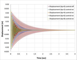
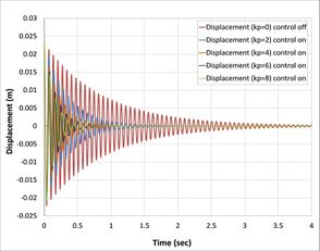
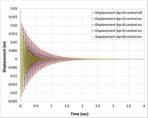
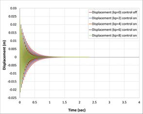
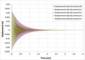
Classical controller (P) is the proportional control and gain (kp) is the only variable to be changed. The present study has been used for (2,4,6, and 8) kp value. The open-loop and closed-loop responses of the tip displacement are shown in Fig.s 5(a), 5(b),5(c), and 5(d), respectively, by using APDL ANSYS. From the graph, it is found that the open-loop response vibrates a lot at a time of more than 5 sec in first Fig. 5(a), 4 sec in second Fig. 5(b), 3.8 in third Fig. 5(c), and 1.25 sec in the last Fig. 5(d) [36]. In the first case, composite laminates consist of three-ply (0/90/0) closed-loop responses by using classical controller when we took into consideration only proportional part effects in PID control, which is shown settle at a time 1.4 sec, 0.85 sec, 0.75 sec and 0.7 sec, respectively, proportional gain (kp) is 2, 3, 6, 8, which demonstrates that three recent responses of the system will be near each other. This reduction in the time compared with the first case is due to the increase in the number of composite layers, and, at the same time, an increase in the strength properties of the beam is observed.
|
| |
| (a) CFRP (0/90/0) | (b) CFRP (0/90/0/90) | |
|
| |
| (c) CFRP (0/90/90/0) | (d) CFRP (0/90/0/90/0/90) | |
| Fig. 5 Open-loop and closed-loop responses of a composite beam of tip displacement.
| ||
However, the evidence for this relationship is conclusive and has been retrieved from PID rules; with increasing the proportional range, the vibration converges slowly and settling time increases. On the other side, the controlling signal has been decreasing by increasing the value of the proportional constant that takes part in PID and neglected integral and derivative parts. Whereas in the second case, composite laminates consist of four plies (0/90/0/90), the closed-loop responses or all proportional gain (kp) shown as in Fig. 5(b) is close to the results of the first case because the effect of the fourth ply is smaller (90 degree) composite ply with the beam in the fourth case, which demonstrates that control responses of the system will be near each other and this reduction in the time compared with others is due to the increase in the number of composite layers and at the same time increases the strength properties of the beam. Based on the results, it has been noted that an increase in laminates of composite plate decreases the vibration and time stability of the system.
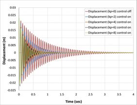
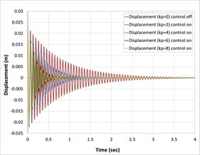
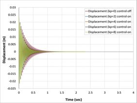
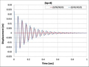
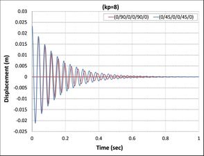
For amplitude comparison between two sets of composite materials beam structures, first set consist of (0-90) degrees of laminates and another set consist of (0-45) degrees of laminates. This based on the responses that were simulated with high accuracy using the proportional gain formulation. As shown in Figs. 5 and 6, all curves have nearly the same shape, but speed to reach the stable case in the second set is smaller than the first set. The reason is attributed to the greater flexural strength for the second compared to the former.
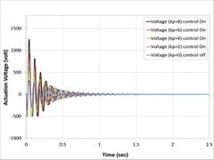
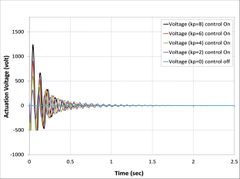
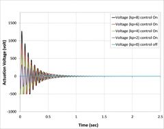
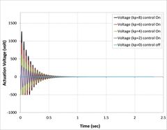
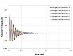
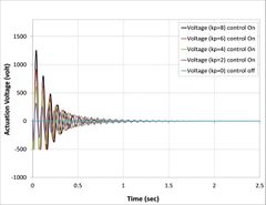
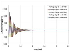
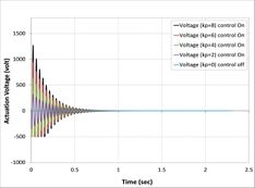
Piezoelectric MFC has a maximum voltage, so it is peak to peak voltage. While peak voltage is the voltage from the zero horizontal axis line to the top of the waveform, the peak to peak voltage is the voltage of the one cycle of a wave, all the way from the peak of the negative side to the peak of the positive side [37]. The maximum voltage for MFC to be applied is (2000 volt) for the piezoelectric actuator. The uncontrolled and controlled responses obtained by actuation voltage can be seen in Figs. 7(a), 7(b), 7(c), 7(d), 7(e), 7(f), 7(g), and 7(h). From the graph, it has been observed that in the open-loop, the response was nil because in the open-loop, there is no link between vibrate response and actuator.
|
|
| (a) CFRP (0/45/0) | (b) CFRP (0/45/0/45) |
|
|
| (c) CFRP (0/45/45/0) | (d) CFRP (0/45/0/45/0/45) |
| Fig. 6 Open-loop and closed-loop responses of the composite beam of tip displacement | |
On the other hand, in all cases, when the control signal applied with the gain to a system increases, the rise time generally decreases as shown in Fig.7, where the actuator voltages for different control gain for all cases are observed to increase with a proportional constant. Meanwhile, kp=8 has the highest value of actuator voltage observed in all cases [38].
As can be seen from Figs. 7(b), 7(c), 7(d), 7(f), 7(g), and 7(h), the minimum value of actuator voltage is (-500V) and smaller than this volt by APDL-ANSYS macro file has been changed to (-500 Volt) because the sinusoidal voltage of piezoelectric MFC-P1 is worked between (-500 volt) to (+1500 Volt) voltage cycle at 0.1 Hz was output by a voltage amplifier [39].
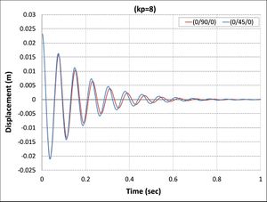
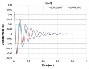
Another important finding was the effect of fiber orientations of composite laminate layers on active vibrations, as shown in Fig.8. The composite beams composed of laminates (0/90/0), (0/90/0/90), (0/90/90/0), and (0/90/0/0/90/0) reach stability faster than the composite beams composed of laminates (0/45/0), (0/45/0/45), (0/45/45/0), and (0/45/0/0/45/0) because the first set has higher relaxation modulus than second sets [40].
|
|
| (a) | (b) |
|
|
| (c) | (d) |
| Fig. 8 Comparision between two sets of similar composite beam | |
5. Conclusions
A FEM for piezoelectric with composite beam structure was proposed to simulate model dynamic, and the electrical model of piezoelectric which permitted the simulations of type ( ) effects. The performance of the composite beam structure is improved when piezoelectric type M8528(P1) is used. It is shown that the classic controller provides in increasing control gain (kp) and better active damping than low control gain, especially at kp=8.
The active control capability of such a composite beam is analyzed using a simple control strategy. Overall, these controlled responses show that, although all different composite laminate plates are subjected to the same intensity of mechanical load. The observed decrease in the vibration of the composite plate might be explained by the increase in the proportional gain in PID control on all cases of the composite laminate plate, while at the same time decreasing the voltage actuator of piezoelectric. The model can be used for more investigations with general composition, applied loads, and another control method. The final objectives of analysis and modeling are the minimization of weight (or mass) of the beam structure under behavior constraints, increasing the performance of the piezoelectric actuator, and maximization of natural frequencies of the vibration modes. However, given the immersed short time for each case, caution must be taken. The difference between two similar different in orientation laminate, two refined finite element models based 0/90 laminate set and 0/45 laminate set, for the analysis of laminated beam with embedded surface bonded piezoelectric laminae have been presented. The evidence from this study suggests the composite beams composed from (0/90) stacking sequence sets had reached stability state faster than the composite beams composed from (0/45) stacking sequencesets.
References
[1] Sun, L., Li, W., Wu, Y. and Lan, Q. Active vibration control of a conical shell using piezoelectric ceramics. Journal of Low Frequency Noise, Vibration and Active Control, 36(4), pp.366-375. ,2017.
[2] Baz, A.M.. Active and Passive Vibration Damping. John Wiley & Sons. , 2019.
[3] Kouider, B. and Polat, A. Numerical investigation of active vibration control of composite plate using PID controller. 2017.
[4] Symans, M.D. and Constantinou, M.C. Semi-active control systems for seismic protection of structures: a state-of-the-art review. Engineering structures, 21(6), pp.469-487, 1999.
[5] Kumar, V. Experimental investigation on active vibration control of smart composite shell structures. PhD thesis ,Jawaharlal Nehru Technological University Hyderabad, 2011.
[6] Manning, W.J., Plummer, A.R. and Levesley, M.C. Vibration control of a flexible beam with integrated actuators and sensors . Smart Materials and Structures, 9(6), p.932, 2000.
[7] Gaudenzi, P., Carbonaro, R. and Benzi, E. Control of beam vibrations by means of piezoelectric devices: theory and experiments . Composite structures, 50(4), pp.373-379, 2000.
[8] Bruant, I., Coffignal, G., Lene, F. and Verge, M. Active control of beam structures with piezoelectric actuators and sensors: modeling and simulation . Smart materials and structures, 10(2), p.404, 2001.
[9] Singh, S.P., Pruthi, H.S. and Agarwal, V.P. Efficient modal control strategies for active control of vibrations . Journal of Sound and Vibration, 262(3), pp.563-575,2003.
[10] Xu, S.X. and Koko, T.S. Finite element analysis and design of actively controlled piezoelectric smart structures . Finite elements in analysis and design, 40(3), pp.241-262 , 2004.
[11] Lim, Y.H. Finite-element simulation of closed loop vibration control of a smart plate under transient loading . Smart Materials and Structures, 12(2), p.272, 2003.
[12] Quek, S.T., Wang, S.Y. and Ang, K.K. Vibration control of composite plates via optimal placement of piezoelectric patches . Journal of intelligent material systems and structures, 14(4-5), pp.229-245, 2003.
[13] Xianmin, Z., Changjian, S. and Erdman, A.G. Active vibration controller design and comparison study of flexible linkage mechanism systems . Mechanism and Machine Theory, 37(9), pp.985-997, 2002.
[14] Halim, D. and Moheimani, S.R. An optimization approach to optimal placement of collocated piezoelectric actuators and sensors on a thin plate . Mechatronics, 13(1), pp.27-47, 2003.
[15] Bendine, K., Boukhoulda, F.B., Haddag, B. and Nouari, M. Active vibration control of composite plate with optimal placement of piezoelectric patches. Mechanics of Advanced Materials and Structures, 26(4), pp.341-349, 2019.
[16] Malgaca, L. Integration of active vibration control methods with finite element models of smart laminated composite structures. Composite Structures, 92(7), pp.1651-1663, 2010.
[17] Takacs, G. and Rohal-Ilkiv, B., April. Direct closed-loop active vibration control system prototype in ANSYS. In INTER-NOISE and NOISE-CON Congress and Conference Proceedings (Vol. 244, No. 1, pp. 1-12). Institute of Noise Control Engineering , 2012.
[18] Vashist, S.K. & Chhabra, D. Optimal placement of piezoelectric actuators on plate structures for active vibration control using genetic algorithm , In Active and Passive Smart Structures and Integrated Systems , International Society for Optics and Photonics, , 9057, p. 9, 2014.
[19] Yavuz, Ş., Malgaca, L. and Karagülle, H. Analysis of active vibration control of multi-degree-of-freedom flexible systems by Newmark method . Simulation Modelling Practice and Theory, 69, pp.136-148 , 2016.
[20] Liu, X., Cai, G., Peng, F. and Zhang, H. Piezoelectric actuator placement optimization and active vibration control of a membrane structure. Acta Mechanica Solida Sinica, 31(1), pp.66-79. https://doi.org/ 10.1007/s10338-018-0005-y, 2018.
[21] Van Tham, V., Quoc, T.H. and Tu, T.M. Optimal placement and active vibration control of composite plates integrated piezoelectric sensor/actuator pairs . Vietnam Journal of Science and Technology, 56(1), p.113, 2018.
[22] Baghaee, M., Farrokhabadi, A. and Jafari-Talookolaei, R.A. Modeling, analysis, and control of MFC sandwiched laminate panel flutter with general layups and arbitrary boundary conditions. Composite Structures, 223, p.110940, 2019.
[23] Usman, M., Hanif, A., Kim, I.H. and Jung, H.J. Experimental validation of a novel piezoelectric energy harvesting system employing wake galloping phenomenon for a broad wind spectrum. Energy, 153, pp.882-889, 2018.
[24] Heganna, S.S. and Joglekar, J.J., 2016. Active vibration control of smart structure using PZT patches. Procedia Computer Science, 89, pp.710-715.
[25] Xie, C., Wu, Y. and Liu, Z., 2018. Modeling and active vibration control of lattice grid beam with piezoelectric fiber composite using fractional order PDμ algorithm. Composite Structures, 198, pp.126-134.
[26] Rimašauskienė, R., Jūrėnas, V., Radzienski, M., Rimašauskas, M. and Ostachowicz, W., 2019. Experimental analysis of active–passive vibration control on thin-walled composite beam. Composite Structures, 223, p.110975.
[27] IEEE, 1984. An American National Standard: IEEE Standard on Piezoelectricity. IEEE Transactions on Sonics and Ultrasonics, (2), pp.1-55.
[28] Abuzaid, A., Hrairi, M. and Dawood, M.S.I., 2015, June. Survey of active structural control and repair using piezoelectric patches. In Actuators (Vol. 4, No. 2, pp. 77-98). Multidisciplinary Digital Publishing Institute.
[29] Heywang, W., Lubitz, K. and Wersing, W. eds., 2008. Piezoelectricity: evolution and future of a technology (Vol. 114). Springer Science & Business Media.
[30] ANSYS, ANSYS Mechanical APDL Basic Analysis Guide/ANSYS help, release 15.0 2013, Inc., Canonsburg, PA, 2017.
[31] Kamel, M.A., Ibrahim, K. and Ahmed, A.E.M. Vibration control of smart cantilever beam using finite element method. Alexandria Engineering Journal, 58(2), pp.591-601,2019.
[32] Trindade, M.A. and Benjeddou, A. Finite element characterisation of multilayer d31 piezoelectric macro-fibre composites . Composite Structures, 151, pp.47-57,2016.
[33] Vijay Kumar, G., Raja, S., Prasanna, K.B. and Sudha, V. Finite element analysis and vibration control of a deep composite cylindrical shell using MFC actuators . Smart Materials Research, 2012.
[34] Smart Materials Corporation. (Accessed Nov 2019). Actuator and sensor ,Available online: https://www.smart-material.com/MFC-product-P1.html
[35] Jimin He and Zhi-Fang Fu , Modal Analysis, Linacre House, Jorden Hill, Oxford , 2001.
[36] Huang, B., Kim, H.S. and Youn, B.D. Active vibration control of smart composite laminates with partial debonding of actuator . International Journal of Precision Engineering and Manufacturing, 16(4), pp.831-840, 2015.
[37] Ian Sinclair . Passive Components for Circuit Design, Linacre House, Jordan Hill, Oxford OX2 8DP, 2004.
[38] Garcia-Segura, T., Yepes, V., Marti, J.V. and Alcala, J. Optimization of concrete I-beams using a new hybrid glowworm swarm algorithm . Latin American Journal of Solids and Structures, 11(7), pp.1190-1205, 2014.
[39] Wu, M., Yuan, X., Luo, H., Chen, H., Chen, C., Zhou, K. and Zhang, D. Enhanced actuation performance of piezoelectric fiber composites induced by incorporated BaTiO3 nanoparticles in epoxy resin . Physics Letters A, 381(19), pp.1641-1647, 2017.
[40] Rony Das. Stress relaxation of ehermostting prepreg composites during cure ,MSc. thesis , Bangladesh University of Engineering and Technology, 2008
Document information
Published on 22/04/20
Accepted on 13/04/20
Submitted on 21/02/20
Volume 36, Issue 2, 2020
DOI: 10.23967/j.rimni.2020.04.001
Licence: CC BY-NC-SA license
Share this document
claim authorship
Are you one of the authors of this document?

