Abstract
In this study, the correlation of loosening and geometry of elbow implant component was investigated using the finite element method. Image processing software was used to construct elbow bones. Humeral and ulnar components were modeled with various cross-sections and flanges using modeling computer-aided design software. Modeling of all stems was based on conventional cemented fixation. Axial torsion and Anterior-posterior force were applied to the articular surface. Zero-displacement was applied to the proximal humerus and distal ulna. Bone graft was used between the flange and distal humerus bone. The stress shielding of bones and micro-motion were obtained in cement-implant-bone interfaces. Results showed that humeral and ulnar stems with modified diamond cross-section observed less micro-motion in the cement-bone-implant interfaces and as well as the least stress shielding in distal humerus and proximal ulna compared to others. Furthermore, the modified flange, concave, transferred the least micro-motion to bone-cement-implant interface and less stress shielding in distal humerus in comparison with trapezium and rectangular ones. This computational analysis represented a step in quantifying the role of interface micro-motion stress shielding of bone in initiating elbow implant loosening. A reduction of micro-motion and stress shielding through design modifications may improve the clinical outcomes.
Keywords Micro-motion, Stress shielding, Loosening, Elbow implant, Finite element analysis
1. Introduction
Despite the wide range of advances in designing of elbow implants, loosening is the most common cause of long-term failure after total elbow arthroplasty (TEA) [1, 2, 3]. Loosening occurs due to three reasons: (1) Stress shielding of the bone (2) Implant-cement-bone micro-motion, and (3) articular surfaces wear [2,4,5]. Loosening is the most important reason to revise cemented elbow implants after surgery. Loosening is considered a mechanical incident, which results in the failure of the bond between the implant and bone bed.
Micro-motion happens at the interface of mating components which belongs to one mechanical system. This phenomenon results in the displacement of a component relative to another one. Micro-motion is considered an engineering issue which points the demand for replacing or revising the implant. The micro-motion should be minimized in the implant-cement-bone interfaces. Micro-motion results in the formation of micro-gaps between the surfaces, Furthermore, micro-motion leads to movement between surfaces and consequently loss of adhesion. With the increase of micro-motion, boundaries in bone-cement-implant interfaces would widen, which eventually leads to migration of implant component and loosening.
Partial unloading of the bone occurs around implanted elbow components. This is due to the fact that stiffness of bone is less than the implant material. Herein, the stress distribution is changed in bone by remodeling which results in bone resorption and increment of the movement between the implant and bone (loosening) [6, 7]. This phenomenon is called stress shielding. Hence, loss of distal humerus, owing to stress-shielding, must be diminished, as it may cause loosening. Therefore, in order to prevent loosening stress shielding and micro-motion must be reduced.
The geometry of the implant is a factor which contributes to loosening of the implant. Generally, implant parameters (stem cross-section, stem length, linkage and flange shape) affects the amount of load transfer from the implant to the bone [8, 9, 10]. Achievement of elbow implant is related to the way mechanical factors are transferred to the surrounding interfaces and bone. This is because the amount of transferred load to the bone is increased by implant parameters and causes rising of micro-motion and stress shielding. The healing of interfacial tissues are related to the micro-motion in interfaces; there are harmful outcomes at higher micro-motion range (e.g. interfacial fibrous tissue formation) however, at the lower range, there is an affirmative effect (e.g. stimulation of interfacial bone formation) [6, 7]. The many modifications have been carried out in the elbow implant after the first TEA. Modification of elbow implants prepares more long-term survival and better functionality of previous designs [11, 12, 13].
Many scientists have modified the implant design in order to find more knowledge of the biomechanics of the elbow. The basis of most of the original designs was a plain hinge joint; consequently, the complete constraint of the articulation resulted in the loosening. The modern implants are categorised in unlinked and linked hinge [14, 15, 16, 17, 18]. Linked implants are influenced by more loosening than unlinked ones. The hinged principle is the basis of linked implants. The snap-fit bushings or pins, as connection parts between humeral and ulnar components, present a semi-constrained structure which permits a small laxity in various directions (rotational, lateral, and medial planes). The loose hinge precisely simulates the normal kinematics elbow. Due to the transfer of a higher rate of stress from the interfaces, the chance of loosening is significantly higher in linked implants than unlinked ones due to receiving higher forces [19, 20].
From the clinical point of view, implant component migration and advanced widening of boundaries in implant-cement-bone interfaces are radiographic indications of loosening. Duparc et al. (1992) reported investigated loosening of attributed in a 2 years follow-up. The whole revised stems were loosened and 60% of them showed micro-motion [21]. The loosening process and micro-motion pattern of an elbow implant were evaluated in a clinical study. The results showed that eight of eighteen humeral components were at risk of loosening; however ulnar components were not at risk of loosening. A lateral flange was recommended flange to improve rotational stability of the transverse and longitudinal axes (Valstar 2002) [22]. A study investigated the rotation and migration of ulnar/humeral components using radiostereometric (RSA) analysis. Early micro-motion was observed for ulnar and humeral stems (Nuttall 2009) [23]. The effect of the various hollow-stemmed implant was assessed to minimize loosening and the impact of stress shielding using FEA by Gross et al. (2001). It was seen the growth of stress in the proximal bone at 15% for the hollow stem compared to stems with similar outside diameter [24]. This shows using different stem shape may decrease stress shielding and finally loosening. Huiske et al. (1992) studied the relationship between bone resorption and implant flexibility using strain-adaptive bone-remodeling theory compared with FEA [25]. The bone adaptation to stress shielding was found as the result of the resorptive, bone which contributes to the rise of loosening. This loosening was occurred due to interfaces micro-motion and interface debonding. Loosening does not appear with clinical symptoms in its primary stages at the present, examination of physical evaluation and periodically radiographic are only clinically methods to define the implant loosening [2].
There are far limited studies on the interface micro-motion and stress shielding in TEA, thus relevant problems and obstacles have not been entirely eliminated. Therefore, it is a call for further investigations and studies. Analyzing factors that could compromise the loosening of linked elbow implant is important to its success. The worth data from presented analyses in this study could reduce loosening. The present study investigated the loosening of an elbow implant using finite element analyses (FEA). This method is useful to modify the implant prior to actual clinical trials. In terms of engineering, if the stem does not pass at this step, it would likely fail clinically.
2 Materilas and ethods
2.1 Modeling of elbow bones
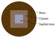
Mimics software (Ver.10, Materialise NV., Belgium), through computed tomography (CT), was used to construct elbow bones. CT data set involved the slice thickness of 0.7mm and the resolution of 0.477mm (Figure 1). Then, the constructed elbow bones were imported into SolidWorks. In this study, SolidWorks software was used for simulated surgery and modeling all components of linked elbow implant. Simulated surgery of humerus and ulna bones was carried out to insert modeled implant into constructed bone. Therefore, a hole was made in humerus/ulna bones and the implant left these bones with a hole. The initial step to prepare of the humerus was bone resection from the midportion of the capitellum and trochlea (Figure 2). As a result, the center axis of flexion-extension was identified. If the capitellum is assumed a circle and sighted from the lateral position of the elbow, the center axis of rotation is placed in the center of the circle. The similar procedure was carried out to prepare ulna (Figure 3). The ulnar component was inserted into the ulna to ensure a good fit before cementing. Conventional cemented fixation was the basis of modeling of all stems therefore, they had smooth surfaces. The optimum thickness of cement (between 1.0 and 1.5 mm) was considered to avoid high failure in cement-bone [26].
(a) (b)
(a) (b) (c) (e)
| |
(a) (b)

|
(c) (e)
2.2 Modeling of Implant components
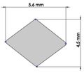
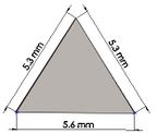
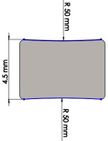
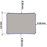
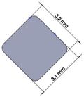
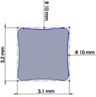
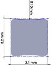
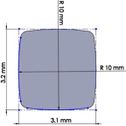
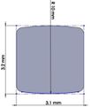
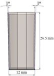
Many efforts have been put into analyzing the ideal stem cross-sectional shape to control implant loosening. Dimension for modeling elbow implant was obtained from a real Coonrad-Morrely implant. Various shapes were modeled to modify a proper cross-section for the humeral component. The cross-sections included diamond, rectangular, triangular, width triangular, concave, and convex. Length of the humeral stem was the same for all cross-sections at 150 mm (Figure 4). Several sub-designs were noticed for the concave cross-section including width concave with variant radiuses (25 mm to 70 mm) and all sides concave. In the same way, different sub-designs were assumed for convex cross-section, including width convex with the different radiuses (25 mm to 70 mm) and all sides convex (Figure 5). Furthermore, various cross-sections including concave, rectangular, convex, diamond modeled to develop a sufficient ulnar component (Figure 6). Several sub-designs were used for concave cross-section including height concave, all sides concave, and width concave (radius from 8 mm to 12 mm). Similarly, different sub-designs were considered for convex cross-section including width convex with various (radius of 8 mm to 12 mm), all sides convex, and height conve (Figure 7).
(a) (b) (c)
(d) (e) (f)
(g) (h)
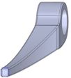
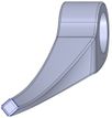
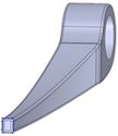
The anterior flange transfers a portion of the load through the elbow prosthesis stem to the distal region of the humerus, which diminishes the probability of humeral loosening [27, 28]. Therefore, the flange was modeled with various shapes including concave, trapezium and rectangular. CT data of distal humerus was used to determine the curve angle of the trapezium model. The angle of where the flange faces distal humerus was nearly 7.3°. These three models were analyzed under the same cross-section (rectangular), the same humeral stem length (150 mm), and similar dimensions (Figure 8). Bone graft was used between the distal humerus and flange. AP compression force (1N) and axial torsion (1N.cm) were applied to the articular surface of the humeral component.
(a) (b) (c) (d)
2.3 Boundary conditions and loading
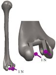
Loading levels compared to the actual physiological loads are considerably less in the majority of FEA models. Mostly, only static joint forces are applied and the rest forces (owing to the activity of ligaments, tendons, and muscles) are omitted [29, 30]. In this study considers AP compression and axial torsion for FEA. In order to simulate axial torsion, a dual force equally was applied to the implant head (articular surface). AP compression (1 N) and torque (1 N.cm) were applied in distal humerus and proximal ulna (Figure 9 and Figure 10). The proximal end of the humerus and distal end of ulna were fixed [31]. Isotropic, homogeneous, and linear elastic materials were considered for implant and interfaces (Table 1) [27, 28, 31, 32].
(a) (b) (c)
Figure 9. Humeral components (a) Applied AP compressionn force (b) Applied axial torsion force (c) Boundary condition
(a) (b)
| Material | Elastic module (GPa) | Poison ratio | ||
| Humeral/Ulnar component (Titanium) | 110 | 0.3 | ||
| Bone | 16.7 | 0.3 | ||
| Cement | 2.28 | 0.3 |
2.4 Mesh convergence
An ulnar stem with a length of 50 mm was inserted into ulna. 2N AP compression force was applied in the proximal end. Mesh of models was carried out using Cosmosworks (Dassault Systemes SolidWorks Corp, USA) software. For this purpose, a series of runs were accomplished with similar conditions except for the size of the element, which was reduced between each run. Tetrahedron element sizes from 4 mm to 0.5 mm were utilized to mesh model (Figure 11).
(b) (c)
2.5 Finite element analysis for predicting micro-motion and stress shielding
The method of relative motion measurement is a significant difference between experimental and finite element predictions of micro-motion. FEA method presents the amount of sliding which happens at the interface through subtracting displacement of outer cement surface from the bone surface and also the displacements at cement surface from the outer surface of the stem. However, experimentally, micro-motion is obtained through displacement transducers mounted on the outer cortex of the bone. The outcomes are generally compared, and low micro-motion is preferred to high micro-motion. Hence, initially displacement was obtained in cement ( , implant (prosthesis) stem , and bone . Next, the displacement results were put in equations (1) and (2) to calculate micro-motion in bone-cement and cement-implant interfaces. To obtain stress shielding, we applied AP compression force in intact humerus and ulna bones. The same load was applied in the implanted humerus and ulna bones with different stem length and cross-sections. Then, firstly, stress was obtained in distal and proximal of intact humerus and ulna bones respectively. Afterward, stress was obtained for implanted humerus and ulna with different parameters in the same locations. Finally, stress shielding was obtained for all models using equations (3).
Micro-motion in implant-cement interface: (1)
Micro-motion in cement-bone interface: (2)
% Stress shielding = (3)
Where is the normal level of stress for un-implanted and stands for the stress of implanted humerus and ulna bones. and are elastic modules of bone and implant respectively. This equation presents the reduction of force in the bone due to the removal of normal stress in bone bone by an implant.
3 RESULTS
3.1 Mesh Convergence
Average Von Mises stress in the ulnar stem is shown in Figure 12. It was seen a considerable diversity between the refined models and coarsest ones. The mesh size of 4 mm showed Von Mises stress at 58 kPa however, stress was 55 kPa for a mesh size of 3.5 mm. A decreasing tendency was observed in stress results from 49 kPa (mesh size of 3 mm) to 42 kPa (mesh size of 1.25 mm). The mesh sizes of 1 mm (41.14 kPa), 0.75 mm (41.15 kPa) and 0.5 mm (41.19 kPa) presented approximately the same stresses. Undoubtedly, more time was spent running the analysis with the mesh size of 0.5 mm and 0.75 mm than the size of 1 mm while, the results were similar. Hence, convergence was reached when there was no qualitative change in the stresses. Consequently, this study was used a mesh size of 1 mm.
3.2 Effect of implant cross-section on micro-motion
Impact of humeral cross-section on micro-motion (under AP compression force) is presented in Figure 13. In the cement-bone interface, the lowest micro-motion was seen at 80 µm (triangular stem) and 52 µm (diamond stem). However, the highest micro-motion was observed at 124 µm (concave R=25 mm) and 118 µm (all sides convex). The same amount was observed at 100 µm for (i) and (h). Among all concave cross-sections, all sides concave presented the lowest micro-motion at 90 µm. For implant-cement interface, the lowest micro-motion was seen at 51 µm for the diamond cross-section. After diamond, triangular stem presented less micro-motion at 76 µm. Approximately, concave stems indicated less micro-motion than convex models.
- (1) (b)
Effect of cross-section on micro-motion of the humeral stem (under torsion force) is shown in Figure 14. In the cement-bone interface, diamond (34 µm) and triangular (90 µm) stems showed the highest and the lowest micro-motions respectively. Two sides triangular (0.5 mm) and concave R=50 mm stems presented the same micro-motion at 74 µm, which was considerably higher than stems with concave R=50 mm, triangular, convex R=25, convex R=50, and convex R=70 mm cross-sections. In the implant-cement interface, the smallest micro-motion was observed in diamond and convex R=50 mm stems at 52 µm and 42 µm respectively while rectangular and all sides concave experienced micro-motion at 103 µm. Figures were slightly increased from convex R=70 (54 µm) to 89 µm for the two sides triangular (1 mm). All sides concave stem showed higher micro-motion (89 µm) than concave R=70 mm and R=50 mm at 81 µm.
(a) (b)
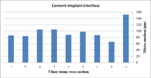
Effect of cross-section on micro-motion of the ulnar stem (under AP compression force) is shown in Figure 15. Results showed a moderate fluctuation in micro-motion. In the cement-bone interface, the highest micro-motion was seen at 150 µm for the rectangular stem, which was double than diamond. The width concave, height concave, and concave R=10 mm stem experienced the same micro-motion at 100 µm. In a similar way, it was seen the same micro-motion at 90 µm for height convex, width convex, and concave R=8 mm stems. In the cement-implant interface, the lowest and highest micro-motions was seen for the diamond stem (66 µm) and rectangular stem (152 µm) respectively. Totally, concave cross-sections transferred higher micro-motion to stems than convex cross-sections. It was seen micro-motion at 105 µm for height and width concave stems, which was considerably higher compared with the width convex and the height at 86 µm.
(a) (b)
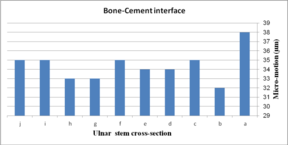
Impact of ulnar cross-section on micro-motion (under torsion force) is shown in Figure 16. A remarkable fluctuation was observed for different cross-sections in the cement-bone interface. The concave R=10 mm and diamond stems showed the lowest micro-motion at 34 µm and 33 µm respectively, while the highest micro-motion was registered for the rectangular stem at 38 µm. The same micro-motion was presented for the height and width convex stems at 35 µm. In the implant-cement interface, figures were seen a relatively different trend. Width and height convex stems presented the second highest micro-motion at 39µm, which was significantly higher than rectangular stem at 43 µm. The lowest micro-motion was observed for the diamond stem at 33 µm following by all sides concave R=12 mm, height concave, and all sides convex R=10 mm at the 35 µm, and consequently, concave R=12 and concave R=10 mm at 36 µm.
(a) (b)
3.3 Effect of flange design on micro-motion
Effect of various flanges on micro-motion of the distal humeral stem (under torsion force) is shown in Figure 17. Under torsion force, a reduction trend was seen in micro-motion from the trapezium to concave flanges. In the cement-bone interface, trapezium flange presented micro-motion at 49 µm. Then, the rectangular flange showed slightly less micro-motion at 39 µm. It was seen the same micro-motion at 32 µm for concave flanges. In the cement-implant interface, micro-motion saw a reduction trend from the trapezium (53 µm) to concave 3˚ (39 µm).
3.4 Effect of implant cross-section on stress shielding
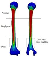
Figure 18 presents the Von Mises stress distribution in implanted and intact humerus (intact humerus acts as a reference) under AP compression. The humerus was assigned into three regions of interest (ROI): distal, diaphyseal, and proximal. Reduction of stress expresses a decrease reduction in the load and consequently the growth of the stress shielding. No effective changes were seen for stress distribution between implanted and intact humerus in diaphyseal and proximal areas. Stress shielding occurred in the distal region. The anterior of the distal area showed stress at 72.90 kPa in the intact humerus.
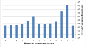
Figure 19 (a) presents average stress in the distal region of the implanted humerus for different cross-sections. The diamond stem showed the highest stress at 66.2 kPa, while all sides convex and rectangular stems experienced the least micro-motion at 60.5 kPa. Triangular stem experienced less stress than the diamond stem (64.45 kPa). Two sides triangular (1mm) and (0.5 mm) stems presented higher stress compared to convex and concave at 61.8 kPa and 63 kPa respectively. The stress shielding for the humeral stem with different cross-sections is shown in Fig. 19 (b). Triangular (6.0%) and diamond (5.8%) stems presented the lowest stress shielding. Approximately, it was seen the same stress shielding at 6.4% for concaves R=50 mm, R=70 mm, rectangular and sides concave stems. Concave stems experienced slightly less stress shielding than convex stems. However, two sides triangular (1 mm), at 6.2%.stem, presented moderately less than two sides triangular (0.5 mm) stem at 6.4%.
(a) (b)
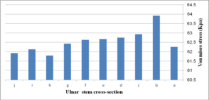
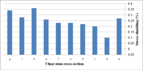
Figure 20 presents the stress distribution in implanted and intact ulna (intact ulna acts as a reference) under AP compression. It was observed the stress distribution in diaphyseal and distal regions. The proximal part experienced stress shielding. In anterior of the proximal area, intact ulna experienced stress at 70.68 kPa. The Von Mises stress distribution in proximal of the implanted ulna is shown in Figure 21 (a). The lowest stress was seen in width concave and all sides concave R=10 mm stems (61.9 kPa), while the highest stress was observed in the diamond stem at 63.9 kPa. Concave stem (R=8) showed the second highest stress at 62.9 kPa. The all sides concave R=12 mm and R=10 mm stems experienced stress at the same amount at 62.8 kPa, while the rectangular stem presented at 62.2 kPa. Effect of cross-section on the stress shielding (under AP compression force) in the ulnar stem is Figure 21 (b). Moderate growth in stress shielding was seen from 6.2% for all sides concave R=8 mm stem to nearly 6.4% for convex R=10 mm stem which presented the highest amount than all models. The lowest stress shielding was registered for the diamond stem at 6.1%. The similar stress shielding was observed for width convex and rectangular stems at approximately 6.3%.
(a) (b)
4 DISCUSSION
In order to control implant loosening, a wide range of efforts has been directed to achieve ideal stem cross-sectional. Although many cross-sections have been studied, concave, convex, and diamond cross-sections have not examined for elbow implants [3, 36, 37, 38, 39]. Yongpravat et al. (2013) used a delta-wing shaped stem was to resist torsional forces [40]. Gschwend et al. (2002) was developed a long ribbed, four edged stems to achieve rotation stability [41]. The data from the analysis of the hip stem may be suitable to modify elbow stem. As an example, smooth stem edges was chosen rather than sharp ones to hinder stress increase at the bone-cement-implant interfaces. Therefore, in the current study, the development of stems was on conventional cemented fixation basis; eventually, all stems possessed smooth surfaces
According to our results, stem with concave cross-section presented higher micro-motions than stem with the convex cross-section in the implant-cement-bone interfaces. In addition, the lowest micro-motion was recorded for the humeral stem with a diamond cross-section at implant-cement-bone interface under both torsion and AP forces than other cross-sections. A similar outcome was seen for ulnar stem under both torsion and AP forces. The obtained values for micro-motion (diamond cross-section) were in the range of the optimum one to decrease loosening. Now, the question is how diamond cross-section causes the lower loosening compared to other cross-sections?
The lack of cement-bone-implant bonding causes loosening which is a consequence of the mechanical failure of implant components. Debonding is the loss of adhesion between two surfaces, which were originally bonded. The growth of the movement in surfaces persuades loss of adhesion. Cause of this movement is micro-motion. Hence, higher micro-motion causes more loss of adhesion, movement, and loosening. Clearly, less movement between interfaces requires a longer time to loosen bone against the implant. Boundaries in bone-cement-implant interfaces are widened through higher movement, which results in migration of implant component (clinically is known as loosening)[1, 4].
Applied axial torsion caused the stem to rotate around an axis perpendicular to the articular surface. Under axial torsion, the anterior-posterior plane plays a more significant role than the mediolateral one. Hence, a number of contact fixation points in frontal and posterior planes are the key to resist torsion. Diamond cross-section presented two fixation points with both bone and cement in the anterior-posterior plane however; the other models presented one point. Diamond cross-section fits the humerus canal in both frontal and posterior planes. It causes self-locking to the endosteal bone through two corners of diamond shape along the whole stem in frontal and posterior planes. This feature results in less movement in interfaces. Therefore, a better distal fit was achieved by having an anterior-posterior point (act as two wings) claiming to improve stability. Hence, diamond cross-section presented considerably less micro-motion compared to rectangular.
The load is comprised of torsional and bending components and it not considered only axial compression. Therefore, a little micro-motion occurs between stem and cement interface during sequential loads, thus, this motion (interface slip) is distributed non-homogenously over the stem due to stem shapes. Motion at the implant-bone interface mostly results in the growth of fibrous around the implant. Clinically, this issue makes implants unstable. It has been found that interfaces micro-motion affects the longevity of implants loosening [42, 43].
Another reason for loosening is stress shielding of bone by the implant [8]. Based on obtained results, diamond cross-section transferred the lowest stress shielding in the proximal ulna and distal humerus. Stress shielding enhances bone loss surrounding an implant as a result of changed (reduced) mechanical stress. The bone resorption occurred in areas where force transferred across the implant bypasses a portion of the bone. External loads are carried all by an intact elbow. However, the capacity of load-carrying is shared by the implant in the implanted bone. Consequently, stress is decreased in bone; therefore, stress is shielded [44].
Diamond cross-section leads implanted ulna and humerus to experience stress closer to the intact bones (natural situation). Therefore, based on Wolff’s Law, humerus and ulna carry less stress shielding. In the other words, the reduction in compression/tension loads by the living bones reduces the thickness of bone thickness and bone mass, which finally causes bone resorption. Ulna and humerus are deposited at locations with higher stresses and are resorbed at locations with little stresses. The decrease of stress relevant to the natural situation ends in bone remodeling (getting thinner). Now, ulna and humerus are resorbed. Here, postoperatively, lack of sufficient bones for implant stability causes implant migration and loosening [8, 45].
In this study, the different stresses were seen between intact and implanted models, which shows a risk of bone resorption by stress shielding in the proximal ulna and distal humerus. Remedios et al. reviewed 25 cemented Kudo implants during in 5 years. Two elbows presented a bone loss in the humerus, which it does not denies the potential risks found by this study [46]. Similarly, in the present study, the decrease in stress in the distal humerus compared with the intact one induces bone resorption. This finding is in agreement with the clinical studies following TEA [47, 48]. The difference in stress distributions between the implanted intact ulna and humerus begins failure of the cement or bone in the stem-tip.
Some studies have investigated the torsional stability of implant stems. Mann et al. (1998), and Chang et al. (1997) showed that circular stem induces less resistance to torsion [49, 50]. Also, a few studies have suggested rectangular stems (Huiskes 1998) [51]. Kedgley et al. (2007), showed the influence of the stem cross-section (triangular, circular, oval, rectangular) on stability and loosening. Stem shape was impressively affected stability and loosening [52]. However, in this study, the modified cross-section (diamond) presented higher resistance to torsion than rectangular. In the current study, all dimensions used for cross-section was the same as those available commercially. This study prepared a fundamental for development and modification of stems under torsion, compression, and other more complex loading modes.
The flange protects the implant-bone-cement interfaces and affects mechanical factors and consequently reduction of implant loosening. Herren et al. (2004) studied the influences of an anterior flange to the GSB III humeral component [53]. No significant diversities were observed in displacements or the stress distribution, indicating the flange had a small influence on this design. Quenneville et al. (2008) studied the impact of a flange on strains in the distal region of the humerus. It was seen that strains are affected by a flange using different geometric [54]. In a similar way, our study proved that micro-motion is affected by the change of flange shape.
Our results showed that a concave flange transfers the lowest micro-motion to the implant-bone-cement interface compared with rectangular and trapezium. Theoretically, the flange increases the rotational stability of the humeral component. The flange affects the transmission of micro-motion to the distal region of humeral stem. Increased micro-motion leads to more movement between surfaces, which widen the boundaries in interfaces and the migration of implant component. Clinically, this migration is seen as radiolucency surrounding the stem. If radiolucency is increased to more than 2 mm, loosening probably occurs. Hence, less micro-motion transferred by the concave flange to interfaces may cause lower loosening.Although the effect of the introduced flange in this study, concave, on micro-motion is little, it probably decreases loosening in a long time. Concave flange may decrease more stress shielding in distal humerus bone rather than other flanges.
ACKNOWLEDGMENT
We acknowledge Global College on Engineering and Technology (Oman), Universiti Sains Malaysia, and Universiti Teknologi MARA for supporting the study.
References
[1] Chafik, D., O’Driscoll, S., King, G.W. (2010) Yamaguchi, K.:Total Elbow Arthroplasty-Convertible. Operative Techniques Orthop. 20: 58-67.
[2] Ren, K., Dusad, A., Zhang, Y., Wang, D. (2013) Therapeutic Intervention for Wear Debris-Induced Aseptic Implant Loosening. Acta Pharmaceutica Sinica. 3(2): 76-85.
[3] Gregory, J.J., Ennis, O., Hay, S.M., (2008)Total elbow arthroplasty. Current Orthop. 22: 80-89
[4] Antuna, S., Vallina, V., (2006) Elbow Arthroplasty: Design, Indications and Results. Rev. Ortop. Traumatol 50: 55-67
[5] Bahraminasab, M., Sahari, B.B., Edwards, K.L., Farahmand, F., Hong, T.S., Naghibi, H., (2013) Material Tailoring of the Femoral Component in a Total Knee Replacement to Reduce the Problem of Aseptic Loosening. Materials and Design 52: 441-451
[6] Yang, D. (2006) Bone/cement Interface in Total Hip Arthroplasty:An in Vitro Study of Bone Surface Preparation, Fatigue and Interface Mechanics, PhD Thesis, University of Maryland, College Park
[7] Ozan, O., Turkyilmaz, I., Ersoy, A.E., McGlumpby, E.A., Rosenstiel, S.F., (2009) Clinical Accuracy of 3 Different Types of Computed Tomography-Derived Stereolithographic Surgical Guides in Implant Placement. J. Oral Maxillofacial Surg. 67(2): 394-401
[8] Bahraminasab, M., Sahari, B.B., Edwards, K.L., Farahmand, F., Arumugam, M., Hong, T.S., (2012) Aseptic loosening of femoral components- A review of current and future trends in materials used. Materials and Design 2: 459-470
[9] Sabatini, A.L., Goswami, T., (2008) Hip implants VII: Finite element analysis and optimization of cross-sections. Materials and Design 29,: 1438-1446
[10] Austman, R.L., Beaton, B.J.B., Quenneville, C.E., King, G.J.W., Gordon, K.D., Dunning, C.E., (2007) The Effect of Distal Ulnar Implant Stem Material and Length on Bone Strains. J. Hand Surg. 32: 848–854
[11] Ericson, A., Olivecrona, H., Stark, A., Maguire, G.Q., Zeleznik, M.P., Arndt, A., (2010) Computed tomography an analysis of radiostereometric data to determine flexion axes after total joint replacement: Application to the elbow joint. J. Biomech. 43: 1947-1952
[12]Hastings, H., (2004) Minimally constrained elbow implant arthroplasty: The discovery elbow system. Tech. Hand Up Extrem Surg. 8: 34-50
[13] Szekeres, M., King, G.J., (2006) Total elbow arthroplasty. J. Hand Ther. 19: 245-253
[14] Heidari, M., Harun, M.N., Syahrom, A., (2014) Influence of polyethylene thickness on axis pin in linked elbow implant. Advanced Materials Research. 845: 194-198
[15] Heidari, M., Harun, M.N., Kadir, M.R.A., Kashani, J., Syahrom, A., (2013) Effect of humeral stem shape on displacement in elbow implant. Applied Mechanics and Materi als 393: 467-471
[16] Heidari, M., Kadir, M.R.A., Kashani, J., Fallahiarezoodar, A., Alizadeh, M., Robson, et al. (2013) Influences of rheumatoid arthritis on elbow: A finite element analysis, J. Advanced Science Letters. 19(11): 3219-3222
[17] Heidari, M., Kadir, M.R.A., Fallahiarezoodar, A., Harun, M.N., Alizadeh, M., kashani J., (2012) Biomechanical assessment of unconstrained elbow prosthesis after total elbow replacement: A finite element analysis. Applied Mechanics and Materials 234: 7-10
[18] Trigg, S.D. (2006) Total Elbow Arthroplasty: Current Concepts. Northeast Florida Med. 57(3)
[19] Sotelo, JS. (2011) Total Elbow Arthroplasty. J. Open Orthop. 5: 115-123
[20] An, K.N., Morrey B.F., (2000) Biomechanics of the elbow. In: Morrey BF,. The elbow and its disorders. W. B. Saunders (Philadelphia)
[21] Duparc, J., Massin, P., (1992) Results of 203 Total Hip Replacements Using A Smooth,Cementless Femoral Component. J. Bone and Joint Sur.(Br.) 74(2): 251- 256
[22] Valstar, E.R., Eric, V.H., Rozing, P.M., (2002) Micromotion of the Souter-Strathclyde total elbow prosthesis in patients with rheumatoid arthritis 21 elbows followed for 2 years. Acta Orthop. Scand. 73(3): 264-272
[23] Nuttall, D., TrailI, A., Stanley, J.K., (2009) Micromotion of the acclaim total elbow arthroplasty using radiosteremetry. J. Bone Joint Surg.Br. 91: 256
[24] Gross, S., Abel, E.W., (2001) A Finite Element Analysis of Hollow Stemmed Hip Prostheses as a Means of Reducing Stress Shielding of the Femur. J. Biomechanics 34: 995-1003
[25] Huiskes, P., Weinans H., Rietbergen, B.V., (1992) The Relationship Between StressShielding and Bone Resorption Around Total Hip Stems and the Effects of Flexible Materials. Clinical Orthopaedics and Related Research 274: 124-34
[26] Day, J.S. (2009) The Clinical Performance of UHMWPE in Elbow Replacements, UHMWPE Biomaterials Handbook, Academic Press (United states)
[27] Amarasinghe, R.S., Rupasinghe, R.A.M., Anurathan, P., Herath, S.R., (2011) Effects of geometry of the interamedullary stem of the ulna component of hinged elbow joint prostheses on the bone and implant bendingstress. J. Mechanics in Med. Biology. 11(5): 1271-293
[28] Prasad, N., Dent, C., (2010) Outcome of total elbow replacement for rheumatoid arthritis: single surgeon’s series with Souter-Strathclyde and Coonrad-Morrey prosthesis. J. Shoulder Elbow Surg. 19: 376-83
[29] Takatori, K., Hashizume, H., Wake, H., Inoue, H., Nagayama N., (2002) Analysis of Stress Distribution in the Humeroradial Joint. J. Orthop. Sci. 7: 650-657
[30] Cheung, E.V., O’Driscoll, S.W., (2007) Total Elbow Prosthesis Loosening Caused by Ulnar Component Pistoning. J Bone Joint Surg Am. 89: 1269-1274
[31] Goel, V.K., Lee, I.I-K., Blair, W.F., (1989) Effect of the Coonrad elbow prosthesis on stresses in the humerus. J. Clin. Biomech. 4: 11-l 6
[32] Completo, A., Pereira, J., Fonseca, F., Ramos, A., Relvas, C., Simões, J., (2011) Biomechanical analysis of total elbow replacement with unlinked iBP prosthesis: An in vitro and finite element analysis. Clin. Biomechan. 26: 990-997
[33] Stokdijk, M., Veeger, H.E.J., de Boera, Y.A., Kozing, P.M., (1999) Determination of the Optimal Elbow Axis for Evaluation of Placement of Prostheses, Clin. Biomechan. 4: 177-184
[34] Godest, A.C., Beaugonin, M., Haug, E., Taylor, M., Gregson, P.J., (2002) Simulation of a Knee Joint Replacement During a Gait Cycle Using Explicit Finite Element Analysis. J. Biomech. 35(2): 267-275
[35] Halloran, J.P., Petrella, A.J., Rullkoetter, P.J., (2005) Explicit Finite Element Modelling of Total Knee Replacement Mechanics. J. Biomech. 38(2): 323-331
[36] Gross, S., Abel, E.W., (2001) A finite element analysis of hollow stemmed hip prostheses as a means of reducing stress shielding of the femur. J. Biomechanics. 34: 995-100
[37] Gregory, J.J., Ennis, O., Hay, S.M., (2008) Total Elbow Arthroplasty, Current Orthop. 2: 80-89
[38] Huiskes, P., Weinans, H., Rietbergen, B.V., (1992) The Relationship Between StressShielding and Bone Resorption Around Total Hip Stems and the Effects of Flexible Materials. Clinical Orthopaedics and Related Research 274: 124-34
[39] Gross, S., Abel, E.W., (2001) A Finite Element Analysis of Hollow Stemmed Hip Prostheses as a Means of Reducing Stress Shielding of the Femur. J. Biomechanics 34: 995-1003
[40] Yongpravat, C., Kim, H.M., Gardner, T.R., Bigliani, L.U., Levine, W.N., Ahmad, G.S., (2013) Glenoid implant orientation and cement failure in total shoulder arthroplasty: a finite element analysis. J Shoulder Elbow Surg. 22: 940-947
[41] Gschwend, N., (2002) Present State of art in elbow arthroplasty. Acta Orthopædica Belgica 68(2): 100-117
[42] Chong, D.Y., Hansen, U.N., [1]Amis, A.A., (2010) Analysis of bone-prosthesis interface micromotion for cementless tibial prosthesis fixation and the influence of loading conditions. J. Biomech. 19(43): 1074-1080
[43] Burke, D.K., O’connor, D., Zalenski, E.B., Jasty, M., Harris, W.H., (1991) Micromotion of cemented and uncemented femoral components. J. Bone Joint Surg. 73: 33-37
[44] Chanlalit, C., Shukla, D.R., Fitzsimmons, J.S., An, K.N., O’Driscoll, S.W., (2012) Stress Shielding Around Radial Head Prostheses. J. Hand Surg. 37: 2118-2125
[45]Wang, A., Sun, D.C., Stark, C., Dumbleton, J.H., (1995) Wear Mechanisms of UHMWPE in Total Joint Replacements. Wear 181: 241-249
[46] Remedios, C., Chantelot, C., Giraud, F., Migaud, H., Fontaine, C., (2005) Results with Kudo elbow prostheses in non-traumatic indications: A study of 36 cases. Acta Orthop. Belg. 71: 273-288
[47] Figgie, H.E., Inglis, A.E., Christopher, B.S., (1986) Total Elbow Arthroplasty in the Face of Significant Bone Stock or Soft Tissue Losses. J. Arthroplasty 1: 71-81
[48]Wixson, R.L., Elasky, N., Lewis, J.L., (1987) Mechanical Properties of Proximal Tibia1 Cancellous Bone in Arthritic Knees. Trans. ORS 33-50
[49] Chang, P.B., Mann, K.A., Bartel, D.L., (1998) Cemented Femoral Stem Performance. Effects of Proximal Bonding, Geometry, and Neck Length. Clin. Orthop. Relat. Res. 355: 57-69
[50] Mann, K.A., Bartel, D.L., Ayers, D.C., (1997) Influence of Stem Geometry on Mechanics of Cemented Femoral Hip Components with a Proximal Bond. J. Orthop. Res. 15(5): 700-706,
[51] Huiskes, R., Verdonschot, N., Nivbrant, B., (1998) Migration, Stem Shape, and Surface Finish in Cemented Total Hip Arthroplasty, Clin. Orthop. Relat. Res. 355: 103-112,
[52] Kedgley, A.E., Lang, P., Dunning, C.E., (2007) The Effect of Cross-Sectional Stem Shape on the Torsional Stability of Cemented Implant Components. J. Biomech. Eng. 129(3): 310-314
[53] Herren, D.B., Ploeg, H., Hertig, D., Klabunde, R., (2004) Modeling and Finite Element Analysis of a New Revision Implant for the Elbow. Clin Orthop. 420: 292-297
[54] Quenneville, C.E., Austman, R.L., King, G.W., Johnson, J.A., Dunning, C.A., (2008) Role of an Anterior Flange on Cortical Strains Through the Distal Humerus After Total Elbow Arthroplasty With a Latitude Implant. J. Hand Surg. 33: 927-931
Document information
Published on 27/03/20
Accepted on 25/03/20
Submitted on 12/12/19
Volume 36, Issue 1, 2020
DOI: 10.23967/j.rimni.2020.03.005
Licence: CC BY-NC-SA license
Share this document
Keywords
claim authorship
Are you one of the authors of this document?


