(→2. Numerical analysis model and theoretical support) |
|||
| Line 31: | Line 31: | ||
To sum up, researchers have made a lot of efforts to obtain good joint properties of Al/Mg dissimilar alloy FSW. Thanks to the uniform heat input on the top and bottom of BT-FSW plate, more thermoplastic materials can be produced at a lower maximum temperature, and faster welding can be realized at a lower rotation speed. However, it is worth noting that the numerical analysis of dissimilar metal welding between 7075 aluminum alloy and AZ31B magnesium alloy using BT-FSW is still blank. At present, it is difficult to monitor the temperature distribution in the welding core area in most experimental studies on aluminum-magnesium dissimilar alloy FSW, and even if the joint forming effect is not good, it can not be explained by thermodynamics. In view of this situation, this study will study the dynamic change trend of asymmetric distribution of temperature and stress of Al-Mg dissimilar alloys during BT-FSW through numerical analysis and experimental verification, and predict the optimal welding parameters and offset, which will provide theoretical reference and technological innovation for the research of Al-Mg dissimilar alloys FSW. | To sum up, researchers have made a lot of efforts to obtain good joint properties of Al/Mg dissimilar alloy FSW. Thanks to the uniform heat input on the top and bottom of BT-FSW plate, more thermoplastic materials can be produced at a lower maximum temperature, and faster welding can be realized at a lower rotation speed. However, it is worth noting that the numerical analysis of dissimilar metal welding between 7075 aluminum alloy and AZ31B magnesium alloy using BT-FSW is still blank. At present, it is difficult to monitor the temperature distribution in the welding core area in most experimental studies on aluminum-magnesium dissimilar alloy FSW, and even if the joint forming effect is not good, it can not be explained by thermodynamics. In view of this situation, this study will study the dynamic change trend of asymmetric distribution of temperature and stress of Al-Mg dissimilar alloys during BT-FSW through numerical analysis and experimental verification, and predict the optimal welding parameters and offset, which will provide theoretical reference and technological innovation for the research of Al-Mg dissimilar alloys FSW. | ||
| − | =2. Numerical analysis model and theoretical support= | + | ==2. Numerical analysis model and theoretical support== |
| − | ==2.1 Material property== | + | ===2.1 Material property=== |
| − | The materials used in this study are 7075 high-strength aviation aluminum alloy and AZ31B magnesium alloy<span id='cite-_Ref28371'></span>[[#_Ref28371|[20]]<span id='cite-_Ref28375'></span>[[#_Ref28375|-21]]], and the composition and proportion of the main alloying elements of the two can be reflected in the pie chart of element content shown in | + | The materials used in this study are 7075 high-strength aviation aluminum alloy and AZ31B magnesium alloy <span id='cite-_Ref28371'></span>[[#_Ref28371|[20]]<span id='cite-_Ref28375'></span>[[#_Ref28375|-21]]], and the composition and proportion of the main alloying elements of the two can be reflected in the pie chart of element content shown in [[#img-1|Figures 1]] and [[#img-2|2]]. |
| − | <div class=" | + | <div id='img-1'></div> |
| − | + | {| class="wikitable" style="margin: 0em auto 0.1em auto;border-collapse: collapse;width:auto;" | |
| + | |-style="background:white;" | ||
| + | |style="text-align: center;padding:10px;"| [[Image:Draft_Zeng_363242613-image1.png|324px]] | ||
| + | |- | ||
| + | | style="background:#efefef;text-align:left;padding:10px;font-size: 85%;"| '''Figure 1'''. 7075 aluminum alloy composition proportion | ||
| + | |} | ||
| − | |||
| − | |||
| − | <div class=" | + | <div id='img-2'></div> |
| − | + | {| class="wikitable" style="margin: 0em auto 0.1em auto;border-collapse: collapse;width:auto;" | |
| + | |-style="background:white;" | ||
| + | |style="text-align: center;padding:10px;"| [[Image:Draft_Zeng_363242613-image2.png|354px]] | ||
| + | |- | ||
| + | | style="background:#efefef;text-align:left;padding:10px;font-size: 85%;"| '''Figure 2'''. AZ31B magnesium alloy element composition proportion | ||
| + | |} | ||
| − | |||
| − | |||
| − | In order to make the simulation results realistic and accurate enough as far as possible, Johnson-Cook constitutive model was used to describe the relationship between temperature, stress-strain, viscoplasticity and other material properties during the welding process. The expression of J-C constitutive model is as follows<span id='cite-_Ref28512'></span>[[#_Ref28512|[22]]]: | + | In order to make the simulation results realistic and accurate enough as far as possible, Johnson-Cook constitutive model was used to describe the relationship between temperature, stress-strain, viscoplasticity and other material properties during the welding process. The expression of J-C constitutive model is as follows <span id='cite-_Ref28512'></span>[[#_Ref28512|[22]]]: |
{| class="formulaSCP" style="width: 100%; text-align: center;" | {| class="formulaSCP" style="width: 100%; text-align: center;" | ||
| Line 56: | Line 62: | ||
{| style="text-align: center; margin:auto;" | {| style="text-align: center; margin:auto;" | ||
|- | |- | ||
| − | | <math | + | | <math>\sigma =(A+B{\epsilon }_{p}^{n})\left( 1+Cln\frac{\overset{\cdot}{\epsilon }}{{\overset{\cdot}{\epsilon }}_{0}}\right) \left[ 1- {\left( \frac{T-{T}_{0}}{{T}_{melt}-{T}_{0}}\right) }^{m}\right]</math> |
|} | |} | ||
| style="width: 5px;text-align: right;white-space: nowrap;" | (1) | | style="width: 5px;text-align: right;white-space: nowrap;" | (1) | ||
|} | |} | ||
| + | where <math display="inline">\sigma</math> is the flow stress; <math display="inline">\overset{\cdot}{\epsilon }</math> is the equivalent plastic strain rate; <math display="inline">{\overset{\cdot}{\epsilon }}_{0}</math> is the reference strain rate; <math display="inline">{\epsilon }_{p}</math> is equivalent plastic strain; <math display="inline">{T}_{melt}</math> is the melting point of the material; <math display="inline">{T}_{melt}</math> indicates the ambient temperature. | ||
| − | + | The J-C constitutive model parameters of 7075 aluminum alloy and AZ31B magnesium alloy are shown in [[#tab-1|Tables 1]] and [[#tab-2|2]]. | |
| − | + | <div class="center" style="font-size: 75%;"> '''Table 1'''. J-C constitutive model parameters of 7075 aluminum alloy</div> | |
| − | <div | + | <div id='tab-1'></div> |
| − | + | {| class="wikitable" style="margin: 1em auto 0.1em auto;border-collapse: collapse;font-size:85%;width:auto;" | |
| − | + | |-style="text-align:center" | |
| − | {| style=" | + | !A/MPa !! B/MPa !! c !! n !! m !!T<sub>melt </sub>/℃ !! T<sub>ref </sub>/℃ |
| − | + | ||
| − | + | ||
| − | | | + | |
| − | + | ||
| − | + | ||
| − | + | ||
| − | + | ||
| − | + | ||
|- | |- | ||
| − | | style=" | + | | style="text-align: center;"|441 |
| − | | style=" | + | | style="text-align: center;"|383 |
| − | | style=" | + | | style="text-align: center;"|0.0083 |
| − | | style=" | + | | style="text-align: center;"|0.183 |
| − | | style=" | + | | style="text-align: center;"|0.859 |
| − | | style=" | + | | style="text-align: center;"|610 |
| − | | style=" | + | | style="text-align: center;"|20 |
|} | |} | ||
Revision as of 11:34, 17 May 2024
Abstract
The theoretical model of bobbin tool friction stir welding (BT-FSW) structure and dynamic process is established. Because of the great differences in properties of different materials, the mathematical relationship between material stress and deformation will be expressed based on 3D transient heat conduction equation and J-C constitutive model. The BT-FSW process of 7075 and AZ31B was analyzed by finite element method, and the field distribution, thermal cycle curve and stress distribution characteristics of different welding areas of the welded material were simulated. To predict and control the non-equilibrium distribution of welding temperature and stress field, the influences of different Rotating speed, welding speed, offset and other variables on the BT-FSW process of 7075/AZ31B aluminum magnesium dissimilar alloy were studied comprehensively. Finally, the reliability of the model is proved by fitting the experimental and numerical analysis results. The research results show that the temperature of BT-FSW presents an “hourglass” symmetrical distribution, and the stress distribution on both sides of the plate is uniform when the aluminum alloy is placed on the advancing side, the stirring tool is offset to the aluminum alloy by 2mm, and the rotating speed and welding speed are 700r/min and 180mm/min, respectively.
Keywords: Dissimilar materials, FSW, Lagrange method, temperature, numerical simulation
1. Introduction
In order to achieve lightweight, reduce fuel consumption, energy saving and emission reduction, aluminum alloy and magnesium alloy, as the most representative lightweight alloys, are widely used in aerospace, rail trains and other manufacturing fields with high requirements for lightweight structure [1-2]. The single 7xxx high-strength aluminum alloy has the characteristics of small density, high specific strength, good thermal conductivity, excellent electrical conductivity, low melting point, but poor wear resistance [3-4]. Magnesium alloy has the advantages of low density, high specific strength, good wear resistance and strong impact resistance [5]. Therefore, in order to take into account the material performance advantages of aluminum alloy and magnesium alloy, it is urgent to realize high-quality welding of aluminum alloy and magnesium alloy in equipment manufacturing. However, the great difference in physical and chemical properties between aluminum/magnesium alloys and the increase in the amount of intermetallic compounds produced in the welding process make it very difficult to weld, especially in the use of conventional fusion welding process, it is easy to appear thermal cracks, oxide inclusions, holes and other defects [6-7].
In 1991, Friction Stir Welding (FSW) was proposed by The Welding Institute (TWI) [8] and was widely used in the welding of non-ferrous metals and dissimilar alloys such as Al-magnesium due to its excellent properties of low heat input, low welding deformation and high dimensional accuracy [9-10]. As a solid phase welding process, FSW is a process in which the heat generated by the intense extrusion and friction between the stirring tool and the material will be heated by the welding material to thermoplastic, and then the material will form a mechanical connection by high-speed stirring [11]. By controlling the process parameters, there is no material melting in the whole welding process of FSW, effectively avoiding the occurrence of solidification defects, and greatly reducing the probability of the generation of brittle intermetallic compounds in the melting state, so as to obtain excellent mechanical properties of the joint [12]. However, in the process of welding aircraft skin or sleeve, conventional Friction stir welding requires harsh support conditions to avoid deformation of shell components, so Bobbin tool Friction stir welding (BT-FSW) without rigid support came into being [13]. Moreover, the traditional FSW is often difficult to weld through the thick plate, which is because the plate thickness further increases the difficulty of heat transfer in the material, the introduction of the second main heat source BT-FSW can effectively solve this problem [14].
In recent years, the research on aluminum and magnesium dissimilar alloy welding has gradually become a new hotspot in the industry, and the technical problems of poor bonding and difficult control of aluminum and magnesium dissimilar alloy FSW process have been studied in many aspects.
Duan et al. based on Euler-Lagrange coupling (CEL) method, numerically simulated the FSW process of 3mm thick AA5A06-AZ31B Al-Mg dissimilar alloy, and revealed the formation mechanism of material mixed flow occlusal interface during dissimilar alloy welding [15]. Nie et al. conducted FSW experiments on 20mm ultra-thick 5A06 aluminum alloy and AZ31B magnesium alloy plates at different rotating speeds, and conducted in-depth exploration on the temperature, joint forming and microstructure of Al-Mg dissimilar alloy FSW process by means of thermocouple temperature measurement, scanning electron microscopy, electron probe and energy spectrum analysis. The influences of rotational speed on temperature and microstructure formation were analyzed [16]. Kong et al. found that intermetallic compounds with Al3Mg2 and Al12Mg17 as the main components were mainly generated on the Mg side through SEM and XRD analysis of five welding areas of 5A06/AZ31B aluminum-magnesium alloy with a thickness of 3mm, which was also the main reason for the low strength of the joint on the Mg side [17]. In order to reduce the impact caused by differences in physical and chemical properties of Al-Mg dissimilar alloy during welding, Kumar et al. added Zn intermediate layer to the center of 6061 aluminum alloy and AZ61 aluminum alloy FSW plate, and studied the influence of Zn intermediate layer on mechanical properties, microstructure and corrosion properties of welded joints. The results showed that, The addition of Zn element is evenly distributed in the weld by stirring, and significantly increases the tensile strength of the joint [18]. Bilgin used open flame to heat the pattern during FSW of AZ31B and AA7075-T6 aluminum alloys, and studied the influence of process parameters on the mechanical properties and microstructure of FSW joints of aluminum/magnesium dissimilar alloys under heat-assisted conditions. It was found that the welding temperature had the greatest influence on the welding quality [19].
To sum up, researchers have made a lot of efforts to obtain good joint properties of Al/Mg dissimilar alloy FSW. Thanks to the uniform heat input on the top and bottom of BT-FSW plate, more thermoplastic materials can be produced at a lower maximum temperature, and faster welding can be realized at a lower rotation speed. However, it is worth noting that the numerical analysis of dissimilar metal welding between 7075 aluminum alloy and AZ31B magnesium alloy using BT-FSW is still blank. At present, it is difficult to monitor the temperature distribution in the welding core area in most experimental studies on aluminum-magnesium dissimilar alloy FSW, and even if the joint forming effect is not good, it can not be explained by thermodynamics. In view of this situation, this study will study the dynamic change trend of asymmetric distribution of temperature and stress of Al-Mg dissimilar alloys during BT-FSW through numerical analysis and experimental verification, and predict the optimal welding parameters and offset, which will provide theoretical reference and technological innovation for the research of Al-Mg dissimilar alloys FSW.
2. Numerical analysis model and theoretical support
2.1 Material property
The materials used in this study are 7075 high-strength aviation aluminum alloy and AZ31B magnesium alloy [20-21], and the composition and proportion of the main alloying elements of the two can be reflected in the pie chart of element content shown in Figures 1 and 2.
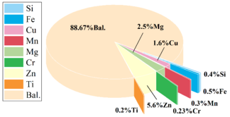
|
| Figure 1. 7075 aluminum alloy composition proportion |
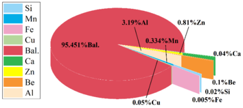
|
| Figure 2. AZ31B magnesium alloy element composition proportion |
In order to make the simulation results realistic and accurate enough as far as possible, Johnson-Cook constitutive model was used to describe the relationship between temperature, stress-strain, viscoplasticity and other material properties during the welding process. The expression of J-C constitutive model is as follows [22]:
|
|
(1) |
where is the flow stress; is the equivalent plastic strain rate; is the reference strain rate; is equivalent plastic strain; is the melting point of the material; indicates the ambient temperature.
The J-C constitutive model parameters of 7075 aluminum alloy and AZ31B magnesium alloy are shown in Tables 1 and 2.
| A/MPa | B/MPa | c | n | m | Tmelt /℃ | Tref /℃ |
|---|---|---|---|---|---|---|
| 441 | 383 | 0.0083 | 0.183 | 0.859 | 610 | 20 |
| A/MPa | B/MPa | n | c | m |
| 228 | 306 | 0.631 | 0.013 | 1.497 |
| d1 | d2 | d3 | d4 | d5 |
| 0.1 | 0.09 | -1.52 | 0.052 | 0 |
2.2 Models and meshing
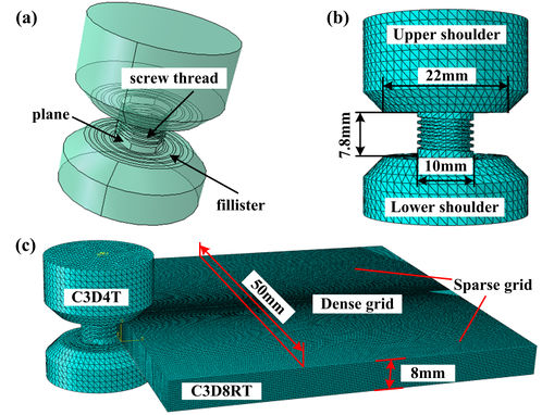
This simulation is a numerical calculation of BT-FSW docking of 8mm 7075 aluminum alloy and AZ31B magnesium alloy plate. As shown in Figure 3(a), the 3D modeling software is used to design a bobbin tool with excellent mixing ability. Considering the high viscosity of magnesium alloy, in order to increase the contact area between the stirring pin and the material during the mixing process, and thus increase its ability to promote the flow of the material, the stirring pin is designed to be cylindrical with threads, and the length is 7.8mm. The section radius is 5mm, a plane is cut out every 120°, and there are curved grooves in the upper and lower shoulder, the diameter of the shoulder is 22mm, and the pressing depth of the upper and lower shoulder is 0.1mm. As shown in Figure 3(b), considering that the structure of the stirring tool is relatively complex, it cannot be divided into hexahedra by splitting, and this is not the focus of this study, so the C3D4T four-node thermal coupled tetrahedron element is used to mesh the stirring tool and set it as a rigid body[23].
Then, a 3D model of the welded sheet with the size of is 100mm×5mm×8mm is constructed, two sheets are endowed with materials and assembled with the stirring tool (the picture shows the assembly state of the welding tool without offset), and the grid is divided one by one. In order to maximize the accurate calculation of numerical analysis, C3D8RT eight-node thermal coupling hexahedral element reduction integral was used to grid the plate, and single precision offset seed was used to save calculation time, so that the grid of the severely deformed stirring zone was densely distributed, and the grid of the base material area on both sides was gradually sparse. The results of model division are shown in Figure 3(c), and all grids adopt the first-order linear reduction integral, which defines the surface-to-surface contact between the stirring tool and the welded material in the FSW simulation system (Lagrange method does not support general contact setting in FSW simulation).
2.3 Mathematical model of heat production
Selecting a reasonable heat source model is the prerequisite for obtaining ideal simulation results. The main source of heat production in the BT-FSW process is the plastic deformation of the material and the friction heat generation between the stirring tool and the material. Therefore, the heat production in this model can be expressed as follows.
Since the bobbin tool has two main heat sources, the friction heat generation between the mixing head and the material is approximately expressed as formula (1):
|
|
(2) |
Where, is the thermal efficiency coefficient of the contact surface; is the slip coefficient; stands for friction coefficient; refers to yield shear stress; stands for welding axial pressure.
The expression relationship of plastic deformation heat production in shear layer is shown in equation (3):
|
|
(3) |
Where, is the thermal efficiency coefficient of the shear layer, represents the material flow stress, and is the strain rate.
The heat generated in the welding process is not completely absorbed by the plate, and part of the heat will pass into the stirring tool. The proportion of the heat transferred into the stirring head is related to the material of the stirring tool and the material to be welded. The mathematical model of heat transfer can be expressed as formula (4):
|
|
(4) |
Where, is the thermal conductivity of the plate, refers to the density of the plate, is the specific heat capacity of the plate, is the thermal conductivity of the mixing head material (the mixing head material here is No. 13 tool steel), is the density of the material used in the mixing head, and is the specific heat of the mixing head material.
Therefore, the total heat input of the plate is expressed as (5):
|
|
(5) |
3. Parameter setting and result analysis
3.1 Parameter setting
Based on the control variable method, the temperature field, stress and strain under different bias and process parameters under BT-FSW process were comprehensively analyzed to determine the optimal parameter model of aluminum/magnesium dissimilar alloy BT-FSW. Therefore, nine sets of simulation parameters were constructed, as shown in Table 3. Among them, magnesium alloy and aluminum alloy are located on the advancing side (AS, the side where the rotation direction of the stirring tool is the same as the welding direction) and retreating side (RS, the side where the rotation direction of the stirring tool is opposite to the welding direction) of FSW process in turn, and the numerical calculation of thermo-mechanical coupling under multi-parameter coupling is carried out for different offset, rotating speed and welding speed.
| Schemes | Plate position(AS/RS) | Offset(mm) | Rotating speed(r/min) | Welding speed(mm/min) |
| 1 | Mg(AS); Al(RS) | No offset | 600 | 240 |
| 2 | Mg(AS); Al(RS) | (to Mg) 1 | 600 | 240 |
| 3 | Mg(AS); Al(RS) | (to Al) 1 | 600 | 240 |
| 4 | Mg(AS); Al(RS) | (to Al) 2 | 600 | 240 |
| 5 | Mg(AS); Al(RS) | (to Al) 2 | 700 | 240 |
| 6 | Mg(AS); Al(RS) | (to Al) 2 | 700 | 180 |
| 7 | Mg(AS); Al(RS) | (to Al) 2 | 800 | 240 |
| 8 | Mg(AS); Al(RS) | (to Al) 2 | 800 | 180 |
| 9 | Al(AS); Mg(RS) | (to Al) 2 | 700 | 180 |
3.2 Numerical results and analysis
3.2.1 Stirring tool offset affects temperature and stress distribution
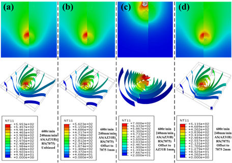
Compared with schemes 1, 2, 3 and 4, the position of the plate was controlled unchanged with other process parameters. At 600r/min rotational speed and 240mm/min welding speed, the thermal coupling analysis temperature nephogram and equivalent surface temperature nephogram of different stirring tool offset states were shown in Figure 4. It can be clearly seen from the cloud image that there is a huge difference in temperature distribution between the aluminum alloy and the magnesium alloy plates in the welding process, and the Mg side is much higher than the Al side. It is worth noting that, taking schemes 1 as an example, by observing the temperature distribution cloud diagram of BT-FSW axial section (as shown in Figure 5), it can be seen that BT-FSW has two main heat sources, the upper and lower shaft shoulders. Different from the "inverted cone" shape temperature cloud diagram of the weld section in the traditional FSW process, the temperature cloud diagram of BT-FSW joint section presents an "hour glass" shape distribution. The heat distribution is more uniform in the direction of plate thickness.
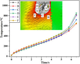
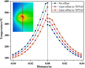
Extract the temperature rise data of any point in the gray high temperature area of the numerical analysis temperature nephogram of schemes 2, and draw the temperature rise curve as shown in Figure 6. Further extract the temperature data along the linear path from the weld center to the base material area during the numerical analysis of schemes 1, 3 and 4, and draw the temperature distribution curve from the weld center to the base material area as shown in Figure 7. It is not difficult to see that in the unbiased state, the temperature distribution of Al/Mg dissimilar alloy BT-FSW is extremely uneven, and the poor thermal conductivity of AZ31B magnesium alloy intensifies the heat accumulation effect on the Mg side. The maximum temperature is significantly higher than that on the 7075 aluminum alloy side, and the temperature difference between Al and Mg sides can reach up to 192.5℃. As a result, there is not enough thermoplastic material on the low temperature Al side to interact with the magnesium alloy, and a large number of thermoplastic magnesium alloys are extruded out of the stirring zone, and defects such as holes and tunnels are formed inside the joint after cooling.
As shown in Figure 4(c) and Figure 6, the above phenomenon will become more obvious when the stirring pin is biased 1mm towards the Mg side. In the initial stage of welding, a molten pool of 700-850℃ is generated on the Mg side, and the numerical analysis mesh is torn.
In contrast, when the stirring tool is tilted to the Al side, the temperature distribution begins to shift to the Al side, and the temperature difference between magnesium and aluminum sides is reduced to 131℃. When the offset to the Al side is 2mm, the maximum temperature of the Mg side is reduced to 483℃, and the maximum temperature of the Al side is 453℃. The temperature difference between the left and right plates is obviously controlled (the difference is reduced to 33℃), which is more conducive to the formation of defectless joints.
Figure 6. Scheme 2 Temperature rise curve of Figure 7. Linear path temperature distribution
random points in the mixing zone curve from weld center to base metal area of scheme 1, 3 and 4
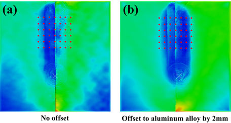
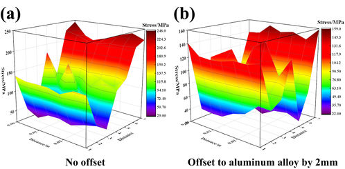
Whether the stress distribution is uniform during the welding process can directly affect the forming quality of the welded joint, and further reflect whether the stirring action of the stirring tool on both sides of the alloy material is consistent. Now, in order to directly reflect the stress distribution law in the forming process of the joint, the stress distribution under the above offset condition and the condition of the stirring tool without offset is compared and analyzed, and the stress distribution nephogram with different offset quantities under the same parameters is shown in Figure 8. On this basis, the 3D model of stress distribution on the welding surface is drawn, as shown in Figure 9 (the position of the lattice has been marked on the stress nephogram). In this model, the stress distribution is shown in the form of peaks, which are gentle in the region of low stress, and steep in the region of large difference in stress distribution.
When the stirring tool is not offset, the material on the Al side is not softened due to the large temperature difference between the left and right of the Al/Mg dissimilar alloy, and the stress generated under the intense agitation of the stirring tool is obviously higher than that on the Mg side, and the trend of the 3D stress graph is obvious. When the stirring tool is shifted to one side of the Al, the stress distribution in the welding process is more symmetrical, and the 3D stress map shows a symmetrical "W" shape trend. Therefore, in the BT-FSW process of 7075/AZ31B dissimilar alloy, in order to obtain a welded joint with no defects, high quality and uniform stress distribution, the stirring tool should be appropriately offset to the Al side, and the offset is determined by the actual parameters such as the shape and thickness of the stirring pin.
3.2.2 Welding parameters affect temperature distribution
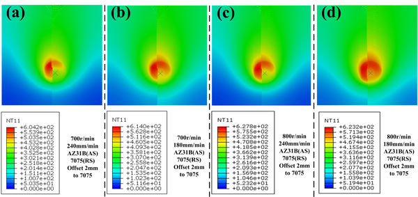
After determining the correct offset of the stirring pin, the process parameters are optimized for the design scheme 4, 5, 6, 7 and 8, and the rotating speed and welding speed are studied in turn under the condition that the offset of the stirring tool is unchanged. The temperature cloud image obtained at 600r/min-800r/min rotating speed and 180mm/min and 240mm/min welding speed is shown in Figure 10. The temperature cloud image of scheme 4 is shown in Figure 4(c).
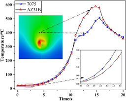
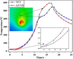
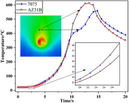
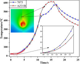
According to the temperature nephogram diagram (Figure 2c) and temperature distribution curve Figure 4(b) of Scheme 4, when the rotating speed is 600r/min and the welding speed is 240mm/min, the maximum temperature in the stirring zone is 511℃. At this temperature, the welding process cannot produce enough thermoplastic materials, resulting in insufficient material flow, which leads to welding defects and weak bonding. Therefore, the rotating speed must be increased to improve the heat input. Extract the temperature rise data of the joints of the heat affected regions of the magnesium alloy and aluminum alloy shoulder in the welding paths of schemes 5, 6, 7 and 8, and draw the temperature rise curve (with the cloud image taking point), as shown in Figure 11.
The melting point of AZ31B magnesium alloy produced by different factories is mostly between 620-650℃, and 7075 aluminum alloy is between 580-610℃. The analysis of temperature nephogram and welding temperature rise curve shows that when the rotating speed is 700r/min and the welding speed is 240mm/min, the maximum temperature of magnesium and aluminum alloy is 589℃ and 507℃ respectively, and the heat input of Al side is obviously insufficient. When the rotating speed is 700r/min and the welding speed is 180mm/min, the maximum temperature in the welding process of magnesium and aluminum alloy reaches 605℃ and 546℃, reaching more than 90% of the respective melting point. At this temperature, there is sufficient thermoplastic material, almost no material is melted, the amount of intermetallic compound is less, and there is no solidification defect caused by cooling. Excellent welding effect and mechanical properties. When the rotating speed is 800r/min and the welding speed is 240mm/min or 180mm/min, the maximum temperature on the magnesium side during the welding process reaches 620℃ or above, and some magnesium alloys begin to melt at this temperature, and the production of brittle intermetallic compounds increases. Moreover, due to the high thermal expansion coefficient of magnesium alloy, solidification porosity defects will occur after welding cooling, which will reduce the mechanical properties after welding.
3.2.3 The position of the plate affects the temperature and stress distribution
Similar to traditional FSW, BT-FSW also has Advancing side (AS) and Retreating side (RS). In the same alloy FSW, RS temperature is often higher than AS, but dissimilar alloys do not follow this rule. The temperature difference between the two sides of the welding is often determined by the physical and chemical properties of the material. In previous studies, researchers have experimentally verified the excellent performance of placing magnesium alloy on the AS in the FSW process of 6061/AZ31B Al-Mg dissimilar alloy[24]. Therefore, this study will for the first time use thermodynamic coupling simulation method to conduct numerical calculation research on the influence of the position change of dissimilar alloy BT-FSW plate on the welding temperature and stress distribution.
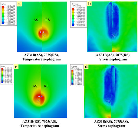
AS shown in Figure 12, the welding temperature and stress distribution nephogram diagram of AS and RS were successively placed on the magnesium alloy under the parameter conditions that the stirring tool was shifted to the side of the aluminum alloy and the rotating speed and welding speed were 700r/min and 180mm/min respectively. It can be seen that no matter how the plate is placed, the stress distribution in the welding process is always relatively uniform, and there is no obvious change; When the magnesium alloy is on the AS, the peak temperature during the welding process is about 614℃, and when the magnesium alloy is placed on the RS under the same conditions, the peak temperature during the welding process is reduced (about 20℃). It can be inferred that placing the AZ31B magnesium alloy with lower strength on the AS is conducive to the production of welding heat. In order to ensure the same peak welding temperature at the same time can properly reduce the speed or increase the welding speed, which is helpful to obtain a good joint forming effect under low energy consumption.
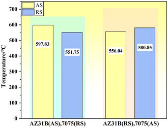
AS shown in Figure 13, for the two sets of results at the same time, two points shown in the nephogram image of AS and RS are taken to extract relevant temperature data and draw temperature comparison bar charts under different plate placement conditions. It can be seen that when the magnesium alloy is placed in AS, the temperature difference between the two sides is about 41.79℃; when the magnesium alloy is placed in RS, the peak temperature of the magnesium alloy is reduced by about 16.98℃, and the temperature difference between the two sides is reduced to 24.81℃. However, it is worth noting that 7075 aluminum alloy and AZ31B magnesium alloy have a melting point temperature difference of about 40℃, so when the magnesium alloy is placed in AS, the temperature distribution of the plates on both sides of the welding is more reasonable.
4. Verification of simulation results
In order to verify the accuracy of the above simulation study in predicting the extreme temperature distribution anomalies and welding failure phenomena in the welding process of 7075-AZ31B dissimilar alloy, and further prove the reliability of the whole set of numerical analysis results, this study will conduct destructive welding experiments of 7075-AZ31B dissimilar alloy under extreme technological conditions. It was set to offset 1mm to the side of AZ31B magnesium alloy, the rotating speed was 800r/min, and the welding speed was 240mm/min. In addition, infrared temperature gun was used to measure the temperature of AS and RS in the stirring zone during the experiment for several times, and the temperature measurement results were compared with the temperature distribution data of numerical analysis. In addition, the simulation uses the same calculation method, boundary conditions, material parameters, predefined fields and other theoretical Settings as above, and performs the finite element simulation under the same parameter conditions as the experiment.
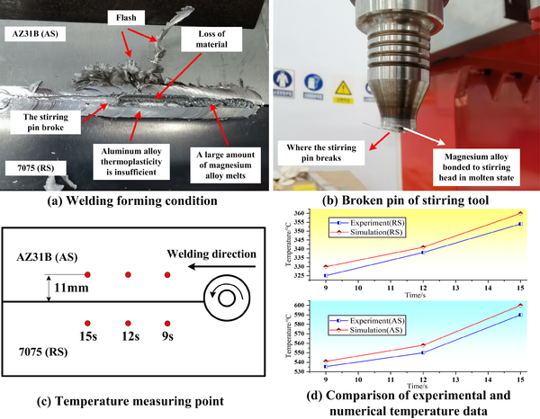
Figure 14 shows the comparison curve of temperature distribution data between the two. Due to the occlusion of the shoulder, infrared temperature measurement cannot directly measure the temperature in the stirring zone below the shoulder, so the measurement position is set to the material surface 11mm away from the weld center. Further observation of the morphology of the stirring zone after welding showed that the melting of Mg side was serious, leaving a large number of flash edges in the welding process, and causing a large number of material missing on the Mg side of the welded joint. However, the temperature of one side of the aluminum alloy is obviously low, and the material is insufficient in thermoplasticity. The difference of material states on both sides causes the aluminum alloy and the magnesium alloy deposited in front of the stirring tool to exert great tangential stress on the stirring tool during the welding process, resulting in the fracture of the stirring pin in the second half of the process. By comparing the temperature measured by experiment with the temperature data extracted by simulation, it is found that the distribution rules of the two are basically the same, and the data fit well, which effectively proves the accuracy of the numerical calculation model for predicting the abnormal distribution of temperature difference in the experiment.
5. Conclusion
This paper conducted a comprehensive study on numerical simulation of BT-FSW process for 7075/AZ31B aluminum/magnesium dissimilar alloy, and comprehensively analyzed the relationship between welding conditions, such as different rotating speed, welding speed, offset amount, and temperature field and stress field of Al-Mg dissimilar alloy BT-FSW process. Through the study, the following conclusions were drawn:
(1) BT-FSW introduces two main heat sources, compared with single-sided welding, the rotating speed is relatively low, the axial temperature is "hourglass" shape symmetrical distribution, heat transfer is more uniform, and completely solves the problem of melting on the upper part of the Al-Mg dissimilar alloy plate and the bottom is not welded through.
(2) The offset of the stirring tool can effectively affect the welding temperature and stress distribution. Under the condition of no offset, the temperature distribution of the left and right plates is extremely uneven due to the huge difference in physical and chemical properties between the AZ31B and the 7075. When the stirring tool is migrated to the Mg side, the extreme situation that the magnesium alloy is melted while the aluminum alloy is still not thermoplastic appears. When the offset of the stirring tool to the Al side reaches 2mm, the temperature difference between Mg and Al sides is reduced to 33℃, the stress distribution is uniform, and the welding conditions are improved.
(3) According to the calculation results of Scheme 4, 5, 6, 7 and 8, the rotating speed and slower welding speed faster, the heat input will be higher. When the rotating speed is 600r/min, the welding heat input will be insufficient, and the risk of material melting will occur when the rotating speed is increased to 800r/min. Only when the rotating speed is 700r/min and the welding speed is 180mm/min, the temperature of the Al/Mg alloy sheet reaches 90% of the melting point, and it is predicted that the flawless joint can be successfully formed at this time.
(4) Changes in the positions of AZ31B magnesium alloy and 7075 aluminum alloy sheets directly affect the peak welding temperature and the temperature difference between Al and Mg alloy in the welding process. Specifically, when magnesium alloy is placed in AS, the peak welding temperature is higher under the same parameter conditions, and the temperature difference between the left and right sheets is suitable. When the magnesium alloy is placed in RS, the temperature difference between the welding peak temperature and the left and right plates decreases. In the BT-FSW welding of 7075 aluminum alloy and AZ31B magnesium alloy, the magnesium alloy is more inclined to be placed on the AS.
Declaration of conflicting interests
The author(s) declared no potential conflicts of interest with respect to the research, authorship, and/or publication of this article.
Acknowledgments
The author(s) disclosed receipt of the following financial support for the research, authorship, and/or publication of this article: Henan Province Science and Technology Research Project (No. 222102240017, 232102241030), Zhengzhou University of Aeronautics laboratory opening project in 2024 (No.ZHSK2453, ZHSK2454, ZHSK2455), Henan Provincial Natural Science Foundation Project (No.232300420106), Scientific Research Team Plan of Zhengzhou University of Aeronautics (No.23ZHTD01006) for their support to this research.
Correspondence
Guang Zeng, Associate professor, Master's supervisor, School of Aerospace Engineering, Zhengzhou University of Aeronautics, Zhengzhou, China. Email: zengg8899@163.com
Data availability statement
The data that support the findings of this study are available from the corresponding author upon reasonable request.
Reference
[1] R.S. Singh, K. Raman, K. Ranvijay, G. Pankaj, S. Sehijpal, P.D. Yurievich, G. Khaled, A. Krzysztof. Joining of Dissimilar Al and Mg Metal Alloys by Friction Stir Welding. Materials, 15(17): 5901-5901, 2022.
[2] M.N. Ahmad, G. Peihao, W. ChuanSong, M. Ninshu. Unravelling the ultrasonic effect on residual stress and microstructure in dissimilar ultrasonic-assisted friction stir welding of Al/Mg alloys. International Journal of Machine Tools and Manufacture, 186, 104004, 2023.
[3] J.X. Zhong, L. Guan, Y. Li, J.Y. Huang, L. Shi. Effect of Second Phase on Corrosion Behavior of Friction stir-welded Joints of 2xxxSeries A-alloy. Journal of Chinese Society for Corrosion and Protection, 43(06): 1247-1254, 2023.
[4] D. Shaik, I. Sudhakar, G.C.S.G. Bharat, V. Varshini, S. Vikas. Tribological behavior of friction stir processed AA6061 aluminium alloy. Materials Today: Proceedings, 44(P1): 860-864, 2020.
[5] S.J. Chen, L. Wang, X.Q. Jiang, Y.L. Wang, T. Yuan. Numerical simulation of electric assisted stationary shoulder friction stir welding of magnesium alloy. The Chinese Journal of Nonferrous Metals, 31(7): 1786−1797, 2021.
[6] D. Cai, L.S. Wang, X.B. Hu. Study on Corrosion Behavior of Friction Stir Welded Joints of AA5052Aluminum/AZ31B Magnesium Alloys. Materials Reports, 37 (04): 151-157, 2023.
[7] J.Z. Li, Q. Wang, P. Zhang. Numerical Simulation of Temperature Field in Friction Stir Welding of 6061 Al Alloy/AZ31 Mg Alloy Dissimilar Metals. Hot Working Technology, 53(9): 59-63, 2024.
[8] R.S. Mishra, Z.Y. Ma. Friction stir welding and processing. Materials Science and Engineering: R: Reports, 50(1-2), 1-78, 2005.
[9] Y. Zou, W. Wei, Y. Fan, Z.Z. Wang, Q. Wang, L. Zhao. Research Progress of Friction Stir Welding of Aluminum Alloy. Hot Working Technology, 53(03): 7-13, 2024.
[10] L.Q. Wang, H.T. Zhou. Research progress in friction stir welding of 7xxx high strength aluminum alloys. Welding & Joining, (10): 47-54, 2023.
[11] P. Yu, C. Wu, L. Shi. Analysis and characterization of dynamic recrystallization and grain structure evolution in friction stir welding of aluminum plates. Acta Materialia, 207, 116692, 2021.
[12] E. Khalid, C.V. Shunmugasamy, B. Mansoor. Dissimilar micro friction stir welding of ultra-thin Mg AZ31 to Al 6061 sheets. Journal of Materials Research and Technology, 21: 1528-1533, 2022.
[13] Q. Wen, W. Li, V. Patel, Y.J. Gao, A. Vairis. Investigation on the Effects of Welding Speed on Bobbin Tool Friction Stir Welding of 2219 Aluminum Alloy. Metals and Materials International, 26(12): 1830-1840, 2019.
[14] G.Q. Huang, D.X. Cheng, H.M. Wang, Q.H. Zhou, Y.F. Shen. Effect of tool probe with a disc at the top on the microstructure and mechanical properties of FSW joints for 6061-T6 aluminum alloy. Journal of Adhesion Science and Technology, 33(22):2462-2475, 2019.
[15] Y.X. Duan, Q.P. Liu, Y.H. Gao, W. Li, L.M. He, P.L. Niu, Y. Xv. Research on Temperature field and Mixed flow of Materials in Al/Mg friction Stir Welding based on CEL method. Rare Metal Materials and Engineering, 52 (07): 2565-2572, 2023.
[16] H. Nie, Y. Xu, L.M. Ke, L. Xing. Effect of Rotational Speed on Frictional Heat Production and lnterface Structure of Thick Plate Al/Mg Dissimilar Materials by Friction Stir Welding. Materials Reports, 37 (08): 88-93, 2023.
[17] D.B. Kong, S.J. Chen, X.G. Jiang. Study on Morphology and Intermetallic Compounds of Aluminum-Magnesium Disimillar Alloy FSW Joint. Hot Working Technology, 51 (11): 12-16, 2022.
[18] P.S. Kumar, J. Das, Q.Y. Shi . Effect of Alloying Foil on the Friction Stir Weld Quality of Mg Alloy Joints. Metallography, Microstructure, and Analysis, 12 (4): 672-682, 2023.
[19] M. Bilgin, Ş. Karabulut, A. Özdemir. Investigation of Heat-Assisted Dissimilar Friction Stir Welding of AA7075-T6 Aluminum and AZ31B Magnesium Alloys. Arabian Journal for Science and Engineering, 45 (64): 1081-1095, 2020.
[20] L. Xie, J.T. Wang, Y.L. Lu, L.Y. Sun, X.H. Yang. Microstructure and properties of bobbin-tool FSW for the 7075 aluminum alloy. Electric Welding Machine, 49(02):55-59, 2019.
[21] R.J. Wang, M.X. Du, P.C. Zhang, Z.Q. Huang, Y. Huang, Z. Chen, X.G. Yan, L.F. Ma. Influence of milling process parameters on surface quality of AZ31B magnesium alloy. Transactions of Materials and Heat Treatment, 43 (11): 151-160, 2022.
[22] G.R. Johnson, W.H. Gook. Fracture character theistic of three metals subjected to various strains strain rates,temperatures and pressures. Engineering Fracture Mechanics, 21(3):31-48, 1985.
[23] S. Zhang, J. Wang. Temperature Field of 6061 Aluminum Alloy by Friction Stir Welding Based on CEL Technique. Journal of Netshape Forming Engineering, 15 (03): 64-71, 2023.
[24] K.P. Mehta, P. Carlone, A. Astarita, F. Scherillo, F. Rubino, P. Vora. Conventional and cooling assisted friction stir welding of AA6061 and AZ31B alloys. Materials Science & Engineering A, 759:252-261, 2019.
Document information
Published on 21/05/24
Accepted on 07/05/24
Submitted on 03/03/24
Volume 40, Issue 2, 2024
DOI: 10.23967/j.rimni.2024.05.004
Licence: CC BY-NC-SA license
Share this document
Keywords
claim authorship
Are you one of the authors of this document?
