ZhouXianjun (talk | contribs) |
|||
| Line 1: | Line 1: | ||
| − | + | <!-- | |
<div class="center" style="width: auto; margin-left: auto; margin-right: auto;"> | <div class="center" style="width: auto; margin-left: auto; margin-right: auto;"> | ||
| Line 24: | Line 24: | ||
{| style="width: 100%;" | {| style="width: 100%;" | ||
|- | |- | ||
| − | | style="vertical-align: top;"|Abstract | + | | style="vertical-align: top;"|--> |
| + | ==Abstract== | ||
In order to reduce the number of hydraulic decoders and hydraulic control pipelines in hydraulically controlled intelligent wells, reduce production costs and improve oil recovery efficiency, the structural design of ICV control of two hydraulic control pipelines and a single hydraulic decoder for four production layers in the well was completed. By simulating the response law of downhole hydraulic signals and the stress analysis of each structure, the motion equation of the layer selection structure of the hydraulic decoder was established with 4 MPa as the unlocking pressure, and ADAMS was used to complete the dynamic simulation analysis. The variation results of displacement, angle, velocity and acceleration in the process of motion were obtained. Finally, the prototype of the hydraulic decoder was processed by stereo photo curing 3D printing equipment. Two hydraulic pumps were used to press alternately, and the selection of four layers of the hydraulic decoder was realized through two hydraulic control pipelines. The self-locking structure could realize the established function, and there was no interference and stuck between the components, which verifies the effectiveness of the design. | In order to reduce the number of hydraulic decoders and hydraulic control pipelines in hydraulically controlled intelligent wells, reduce production costs and improve oil recovery efficiency, the structural design of ICV control of two hydraulic control pipelines and a single hydraulic decoder for four production layers in the well was completed. By simulating the response law of downhole hydraulic signals and the stress analysis of each structure, the motion equation of the layer selection structure of the hydraulic decoder was established with 4 MPa as the unlocking pressure, and ADAMS was used to complete the dynamic simulation analysis. The variation results of displacement, angle, velocity and acceleration in the process of motion were obtained. Finally, the prototype of the hydraulic decoder was processed by stereo photo curing 3D printing equipment. Two hydraulic pumps were used to press alternately, and the selection of four layers of the hydraulic decoder was realized through two hydraulic control pipelines. The self-locking structure could realize the established function, and there was no interference and stuck between the components, which verifies the effectiveness of the design. | ||
| − | + | '''Keywords''': Hydraulic decoder, inverse cylinder cam, self-lock structure, dynamic simulation | |
|} | |} | ||
| − | =1. Introduction= | + | ==1. Introduction== |
The hydraulic decoder provides different pressure signals through the wellhead power generation system above the well to drive the movement of the downhole decoding device, so as to realize the layer selection. After selecting different horizons, the flow of the corresponding horizon could be controlled by the flow control valve, and the pressure of each production layer and the velocity of the fluid could be adjusted in real time [1]. As a key component of the hydraulic control intelligent well, it plays a very important role in improving the efficiency and quality of oil production. | The hydraulic decoder provides different pressure signals through the wellhead power generation system above the well to drive the movement of the downhole decoding device, so as to realize the layer selection. After selecting different horizons, the flow of the corresponding horizon could be controlled by the flow control valve, and the pressure of each production layer and the velocity of the fluid could be adjusted in real time [1]. As a key component of the hydraulic control intelligent well, it plays a very important role in improving the efficiency and quality of oil production. | ||
| − | WellDynamics first applied direct hydraulic system and micro hydraulic system as early as 1998 [2, 3]. Digital hydraulic system can control up to six layers of underground through three pipelines [2, 4]. The hydraulic intelligent well system developed by BakerHughes was mainly InForce, which could control three layers of underground through a 1 / 4in control line and an auxiliary pipeline in each layer [5]. | + | WellDynamics first applied direct hydraulic system and micro hydraulic system as early as 1998 [2,3]. Digital hydraulic system can control up to six layers of underground through three pipelines [2,4]. The hydraulic intelligent well system developed by BakerHughes was mainly InForce, which could control three layers of underground through a 1/4in control line and an auxiliary pipeline in each layer [5]. |
| − | Zhang | + | Zhang et al. [5] proposed a layer selection scheme of miniature hydraulic decoder. Each layer of miniature hydraulic decoder used a two-position four-way valve, a hydraulic control pipeline and a return oil pipeline. Through the change of high and low pressure, the two ends of the flow control valve were controlled respectively to realize the opening and closing of the flow control valve, so as to realize the decoding function. However, this hydraulic decoding system was suitable for oil wells with less than 3 layers. |
| − | Guo | + | Guo [6] and Zhang [7] proposed, respectively, a design scheme of hydraulic decoder in the paper. The whole hydraulic decoder system included layer unlocking module, pressure value signal decoding module, etc., which could realize the selection and throttle control of up to four states and six layers in a single layer. |
| − | Zhao | + | Zhao [8] designed a hydraulic decoder in the paper. The decoder was installed in the front end of the flow control valve, and the flow control valve of the corresponding layer was unlocked through three control pipelines in different application sequences. Similarly, the three control pipelines could also realize the control of up to six layers. |
| − | Jia | + | Jia [9] and Li [10] each proposed a design method of underground hydraulic decoding system based on three hydraulic control pipelines in their paper. The basic idea was to realize the rotation and locking of the valve core through the cooperation of a new hydraulic directional valve and a toothed rotating valve core and a spring. When the valve core rotated to different positions, different layers can be selected. |
The existing hydraulic decoder mostly adopts the scheme of three hydraulic control pipelines to control up to six production layers, which increases the number of hydraulic decoders and pipelines, improves the complexity of pipeline logic and increases the technical difficulty when crossing the packer. Therefore, it is of great significance to innovate the control strategy and structure of hydraulic decoder to improve oil production efficiency and quality. | The existing hydraulic decoder mostly adopts the scheme of three hydraulic control pipelines to control up to six production layers, which increases the number of hydraulic decoders and pipelines, improves the complexity of pipeline logic and increases the technical difficulty when crossing the packer. Therefore, it is of great significance to innovate the control strategy and structure of hydraulic decoder to improve oil production efficiency and quality. | ||
| − | =2.Hydraulic decoder structure design= | + | ==2.Hydraulic decoder structure design== |
| − | ==2.1 Overall design of hydraulic decoder== | + | ===2.1 Overall design of hydraulic decoder=== |
| − | According to the size of the oil well and the structure and technological requirements of the hydraulic decoder, the relevant design parameters are shown in Table 1. | + | According to the size of the oil well and the structure and technological requirements of the hydraulic decoder, the relevant design parameters are shown in [[#tab-1|Table 1]]. |
| − | <div class="center" style=" | + | <div class="center" style="font-size: 75%;">'''Table 1'''. Design parameters of hydraulic decoder</div> |
| − | + | ||
| − | {| style=" | + | <div id='tab-1'></div> |
| + | {| class="wikitable" style="margin: 1em auto 0.1em auto;border-collapse: collapse;font-size:85%;width:auto;" | ||
| + | |-style="text-align:center" | ||
| + | ! The parameter types !! Parameters size | ||
| + | |-style="text-align:center" | ||
| + | | Casing | ||
| + | | <math>4^{1/2}</math> in, size 100.7 mm | ||
| + | |-style="text-align:center" | ||
| + | | Oil tube | ||
| + | | <math>1^{1/2}</math> in, Outer diameter 48.3 mm | ||
| + | |-style="text-align:center" | ||
| + | | Hydraulic decoder depth | ||
| + | | 1000 m | ||
| + | |-style="text-align:center" | ||
| + | | Control the number of pay zones | ||
| + | | 4 | ||
| + | |-style="text-align:center" | ||
| + | | >Unlock pressure | ||
| + | | 4 MPa | ||
| + | |} | ||
| + | |||
| + | |||
| + | ====2.1.1 Overall structure of hydraulic decoder==== | ||
| + | |||
| + | The hydraulic decoder mainly included hydraulic cylinder sealing structure, self-locking structure, layer selection structure, hydraulic valve structure and its supporting springs, pins, bolts and pipelines. The overall structure is shown in [[#img-1|Figure 1]]. | ||
| + | |||
| + | <div id='img-1'></div> | ||
| + | {| class="wikitable" style="margin: 1em auto 0.1em auto;border-collapse: collapse;width:auto;" | ||
| + | |-style="background:white;" | ||
| + | |align="center" | | ||
| + | {| | ||
| + | |+ | ||
|- | |- | ||
| − | | | + | |style="text-align: center;padding:10px;"|[[Image:Draft_Zhou_383413669-image1.png|378px]] |
| − | | | + | |
|- | |- | ||
| − | | | + | |style="text-align: center;font-size: 75%;padding-bottom:10px;"|(a) External overall structure |
| − | + | ||
|- | |- | ||
| − | | | + | |style="text-align: center;padding:10px;"| [[Image:Draft_Zhou_383413669-image2.png|360px]] |
| − | | | + | |
|- | |- | ||
| − | | | + | |style="text-align: center;font-size: 75%;padding-bottom:10px;"|(b) Internal overall structure |
| − | + | ||
|- | |- | ||
| − | | | + | |colspan="2" style="text-align: center;font-size: 75%;padding-bottom:10px;"|1−Lower cover; 2-Lowercavity; 3-Fixed pins; 4-Upper cavity; 5-Upper cover; 6-Limit sliding sleeve; 7-reset spring; 8-Thrust ball bearings; 9-Hydraulic valve fixed seat; 10-Hydraulic valve; 11- Movement sliding sleeve; 12-Pipeline joints ; 13-Guide rod; 14-Fixed pins; 15-Reverse cylindrical cam ; 16-Rotary sliding sleeve; 17-Fixed sliding sleeve; 18-Thrust sliding sleeve; 19-Limited block; 20-Piston; 21-O-ring retaining ring; 22-O circle |
| − | + | |} | |
|- | |- | ||
| − | | | + | | style="background:#efefef;text-align:left;padding:10px;font-size: 85%;"| '''Figure 1'''. Overall structure of hydraulic decoder |
| − | | | + | |
|} | |} | ||
| − | |||
| − | |||
| − | |||
| − | |||
| − | |||
| − | |||
| − | |||
| − | |||
| − | |||
| − | |||
| − | |||
| − | |||
| − | |||
| − | |||
| − | |||
| − | |||
| − | |||
| − | |||
| − | |||
| − | |||
| − | |||
| − | ===2.1.2 Overall structure of hydraulic decoder=== | + | ====2.1.2 Overall structure of hydraulic decoder==== |
During operation, the pipeline 2 connected to the upper end of the decoder is first pressurized to drive the sliding sleeve to move, and the guide rod on the anti-cylindrical cam contacts the hydraulic valve of the corresponding layer, which is connected by mechanical force. Then the pressure of this pipeline is relieved, and pipeline 1 is pressurized, at this time, the piston is reset, and each sliding sleeve moves backward under the action of the return spring. The rotating sliding sleeve is stuck after rotating at a certain angle due to its contact with the fixed sliding sleeve, so as to realize the locking of the mechanism at this time, because the hydraulic valve has been turned on, the flow control valve of this layer can be operated normally. | During operation, the pipeline 2 connected to the upper end of the decoder is first pressurized to drive the sliding sleeve to move, and the guide rod on the anti-cylindrical cam contacts the hydraulic valve of the corresponding layer, which is connected by mechanical force. Then the pressure of this pipeline is relieved, and pipeline 1 is pressurized, at this time, the piston is reset, and each sliding sleeve moves backward under the action of the return spring. The rotating sliding sleeve is stuck after rotating at a certain angle due to its contact with the fixed sliding sleeve, so as to realize the locking of the mechanism at this time, because the hydraulic valve has been turned on, the flow control valve of this layer can be operated normally. | ||
Revision as of 11:30, 12 April 2023
Abstract
In order to reduce the number of hydraulic decoders and hydraulic control pipelines in hydraulically controlled intelligent wells, reduce production costs and improve oil recovery efficiency, the structural design of ICV control of two hydraulic control pipelines and a single hydraulic decoder for four production layers in the well was completed. By simulating the response law of downhole hydraulic signals and the stress analysis of each structure, the motion equation of the layer selection structure of the hydraulic decoder was established with 4 MPa as the unlocking pressure, and ADAMS was used to complete the dynamic simulation analysis. The variation results of displacement, angle, velocity and acceleration in the process of motion were obtained. Finally, the prototype of the hydraulic decoder was processed by stereo photo curing 3D printing equipment. Two hydraulic pumps were used to press alternately, and the selection of four layers of the hydraulic decoder was realized through two hydraulic control pipelines. The self-locking structure could realize the established function, and there was no interference and stuck between the components, which verifies the effectiveness of the design.
Keywords: Hydraulic decoder, inverse cylinder cam, self-lock structure, dynamic simulation |}
1. Introduction
The hydraulic decoder provides different pressure signals through the wellhead power generation system above the well to drive the movement of the downhole decoding device, so as to realize the layer selection. After selecting different horizons, the flow of the corresponding horizon could be controlled by the flow control valve, and the pressure of each production layer and the velocity of the fluid could be adjusted in real time [1]. As a key component of the hydraulic control intelligent well, it plays a very important role in improving the efficiency and quality of oil production.
WellDynamics first applied direct hydraulic system and micro hydraulic system as early as 1998 [2,3]. Digital hydraulic system can control up to six layers of underground through three pipelines [2,4]. The hydraulic intelligent well system developed by BakerHughes was mainly InForce, which could control three layers of underground through a 1/4in control line and an auxiliary pipeline in each layer [5].
Zhang et al. [5] proposed a layer selection scheme of miniature hydraulic decoder. Each layer of miniature hydraulic decoder used a two-position four-way valve, a hydraulic control pipeline and a return oil pipeline. Through the change of high and low pressure, the two ends of the flow control valve were controlled respectively to realize the opening and closing of the flow control valve, so as to realize the decoding function. However, this hydraulic decoding system was suitable for oil wells with less than 3 layers.
Guo [6] and Zhang [7] proposed, respectively, a design scheme of hydraulic decoder in the paper. The whole hydraulic decoder system included layer unlocking module, pressure value signal decoding module, etc., which could realize the selection and throttle control of up to four states and six layers in a single layer.
Zhao [8] designed a hydraulic decoder in the paper. The decoder was installed in the front end of the flow control valve, and the flow control valve of the corresponding layer was unlocked through three control pipelines in different application sequences. Similarly, the three control pipelines could also realize the control of up to six layers.
Jia [9] and Li [10] each proposed a design method of underground hydraulic decoding system based on three hydraulic control pipelines in their paper. The basic idea was to realize the rotation and locking of the valve core through the cooperation of a new hydraulic directional valve and a toothed rotating valve core and a spring. When the valve core rotated to different positions, different layers can be selected.
The existing hydraulic decoder mostly adopts the scheme of three hydraulic control pipelines to control up to six production layers, which increases the number of hydraulic decoders and pipelines, improves the complexity of pipeline logic and increases the technical difficulty when crossing the packer. Therefore, it is of great significance to innovate the control strategy and structure of hydraulic decoder to improve oil production efficiency and quality.
2.Hydraulic decoder structure design
2.1 Overall design of hydraulic decoder
According to the size of the oil well and the structure and technological requirements of the hydraulic decoder, the relevant design parameters are shown in Table 1.
| The parameter types | Parameters size |
|---|---|
| Casing | in, size 100.7 mm |
| Oil tube | in, Outer diameter 48.3 mm |
| Hydraulic decoder depth | 1000 m |
| Control the number of pay zones | 4 |
| >Unlock pressure | 4 MPa |
2.1.1 Overall structure of hydraulic decoder
The hydraulic decoder mainly included hydraulic cylinder sealing structure, self-locking structure, layer selection structure, hydraulic valve structure and its supporting springs, pins, bolts and pipelines. The overall structure is shown in Figure 1.
2.1.2 Overall structure of hydraulic decoder
During operation, the pipeline 2 connected to the upper end of the decoder is first pressurized to drive the sliding sleeve to move, and the guide rod on the anti-cylindrical cam contacts the hydraulic valve of the corresponding layer, which is connected by mechanical force. Then the pressure of this pipeline is relieved, and pipeline 1 is pressurized, at this time, the piston is reset, and each sliding sleeve moves backward under the action of the return spring. The rotating sliding sleeve is stuck after rotating at a certain angle due to its contact with the fixed sliding sleeve, so as to realize the locking of the mechanism at this time, because the hydraulic valve has been turned on, the flow control valve of this layer can be operated normally.
When the layer needs to be closed, pipeline 2 is pressurized again, pushing each sliding sleeve to move a certain distance, triggering the unlocking structure, rotating the sliding sleeve to rotate at a certain angle again to unlock the sliding sleeve, and then pipeline 1 is pressurized. Under the action of the return spring, each sliding sleeve moves to the initial position at this time, the anti-cylindrical cam rotates by a fifth of a turn, when the layer selection movement is carried out again, the next layer will be selected.
2.2 Force analysis of sliding sleeve and establishment of motion equation
The designed inner diameter of the hydraulic cylinder was 76 mm, and the selected piston diameter was 62 mm, at this time, the area of the piston ring cavity was 1516.62 mm2. According to the pressure provided by the hydraulic power generation system above the well, the maximum thrust on the sliding sleeve in the decoder was 6066 N.
2.2.1 Response law of downhole hydraulic signal
Established a long-distance pipeline in AMESim software to simulate the pressure change trend of the port at the depth of 1000 m underground. For a long-distance pipeline of 1 000 m, a more reasonable HL0040 pipeline model was adopted. In the model, a relief valve was set as a safety valve, a constant pressure source with a pressure of 40 bar was used, and a zero flow source was set at the other end of the pipeline.
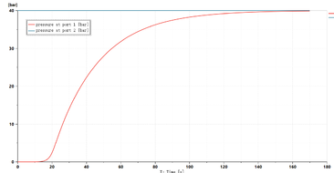
As shown in Figure 2, the pressure at port2 port was always maintained at 40 bar, while the pressure at port1 port had hardly changed in the first 15 s, proved that the pressure transmission time under this condition was at least 15 s. The pressure could reach about 40 bar at 160 s.
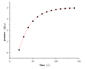
Through fitting the functional relationship of pressure change at 1000 m position is shown in formula (1). The vertical axis is the port pressure (MPa), and the horizontal axis is the time (s). The fitting image of pipeline pressure change is shown in Figure 3.
|
|
(1) |
The functional relationship of the thrust F acting on the piston ring cavity surface is shown in formula (2).
|
|
(2) |
2.2.2 Stress analysis of key components and design of return spring
(1) Friction calculation between hydraulic cylinder and O-ring
Since the hydraulic decoder was 1000 meters underground, the gravity of the hydraulic oil in the pipeline must be considered. Here, the pressure loss of the pipe wall was ignored. Before pressurization, the initial pressure P0could be calculated as 8.43 MPa according to the hydraulic oil density and well depth.
When the piston was in motion, the O-ring on it will produce a large friction force with the hydraulic cylinder due to the large compression rate. The friction force was composed of the force FPrecompression generated by the pre compression of the O-ring and the pressure F1 of the hydraulic oil. According to the empirical formula, the friction is calculated as shown in formula (3) [11].
|
|
(3) |
Where, Ff1 is the total friction generated by the O-ring, N; f is the friction coefficient; D is the outer diameter of O-ring, mm; d is the section diameter of O-ring, mm; μ Is the Poisson's ratio of O-ring; E is the elastic modulus of O-ring, MPa; P is the pressure provided by hydraulic oil, MPa.
In the first 15s of pressurization, due to the pressure delay, this part of friction was only generated by the pre compression of the O-ring, when the pressure began to change, the friction would change, after calculated, the friction generated by the O-ring is shown in formula (4).
|
|
(4) |
(2) Friction between self-locking structures
Since the thrust sliding sleeve and the rotary sliding sleeve of the self-locking structure were contacted through a 45° inclined surface, and the two sliding sleeves were limited in the chute of the fixed sliding sleeve, the friction force during their movement was large. As shown in Figure 4, the stress analysis of the two sliding sleeves was carried out. Figure 4 (a) shows the stress of the thrust sliding sleeve, and figure 4 (b) shows the stress of the rotating sliding sleeve.

|

|
| (a) Force on thrust sliding sleeve | (b) Force on rotating sliding sleeve |
In the figure , at this time , the friction coefficient was taken as 0.15, and the friction force of a single sliding sleeve was 0.15 FPush. Since the forces on the two sliding sleeves were mutual and in contact with the fixed sliding sleeve respectively, the total friction force of the self-locking structureFf2 was 0.3 FPush, and the size is shown in formula (5).
|
|
(5) |
(3) Sliding sleeve gravity and other friction
The friction force during the movement of other sliding sleeves was estimated by gravity, the mass m of the sliding sleeve was estimated to be 20 Kg, took the friction coefficient between the sliding sleeve and the oil pipe as 0.15, the friction force Ff3 was about 30 N and the gravity G was about 200 N.
The unlocking and resetting of the sliding sleeve in the hydraulic decoder was realized by the return spring installed at the bottom, because the spring needed to overcome the gravity of the sliding sleeve to reset it when unlocking, the spring preload F0 was set as 300 N.
2.2.3 erivation of motion equation of decoder
When a certain layer was selected, the piston and each sliding sleeve moved forward, at this time, took the direction of piston movement as positive, the following motion equation could be obtained, as shown in formula (6). The compression y(x) of the spring is the displacement of the sliding sleeve and is a function of time x.
|
|
(6) |
Since the sliding sleeve had no movement 15 s before pressurization, it did not meet the above equation, after finishing, it is shown in formula (7).
|
|
(7) |
In the process of resetting, due to the large friction between the O-ring and the wall, it was difficult for the return spring to push the piston to reset, so pipeline 1 was required to pressurize to assist the piston to reset. At this time, the basic law of sliding sleeve movement was similar to that of locking, and the motion equation is shown in formula (8).
|
|
(8) |
The equation of motion of each time period is sorted out as shown in formula (9).
|
|
(9) |
When selecting layers, the function image is shown in Figure 5, and the function relationship is shown in formula (10).

|

|
| Fig 5. Image of displacement-time function at layer selection | Fig 6. Image of displacement - time function when deselecting layers |
| (10) |
The equation of motion when canceling layer selection is shown in equation (11), and its function image is shown in Figure 6. There would also be a sudden change in speed at the beginning of reset.
| (11) |
3 Dynamic analysis of hydraulic decoder
3.1 Model establishment and parameter setting
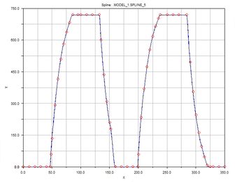
During the simulation, the model was simplified, and only the components that affect the motion were retained, as shown in Figure 7. The force exerted on the sliding sleeve in a motion cycle is shown in formula (12), and the established function curve is shown in Figure 8which is defined as external load.
|
|
(12) |
3.2 Analysis of dynamic simulation results
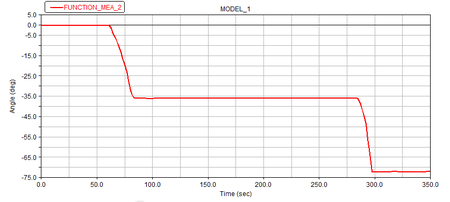
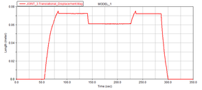
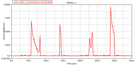
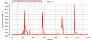
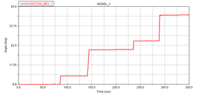
Figure 9 shows the time-displacement image of the sliding sleeve, figure 10 shows the speed time image of the sliding sleeve, figure 11 shows the acceleration time image of the sliding sleeve, figure 12 shows the rotation angle change of the rotating sliding sleeve, and figure 13 shows the angle change of the anti-cylindrical CAM during the movement.
It can be seen from the image that the sliding sleeve started to move around 55 s, with the maximum velocity of 0.009 m / s and the maximum acceleration of 0.092 m / s2. When the external load decreased, the sliding sleeve displacement decreased by about 0.01 m under the action of the reset spring, and remained unchanged. It proved that the fixed sliding sleeve had fixed the position of the rotating sliding sleeve at this time. The angle change of the rotating sliding sleeve corresponded to the time of the sliding sleeve displacement change. When the sliding sleeve displacement reached the maximum, 5° deflection occurred. When the sliding sleeve was locked and unlocked, 15° deflection occurred. Since the number of layers was four, there was another vacancy. Therefore, for each complete motion of a period, the rotation angle of the anti-cylindrical cam should be 72°. When the selection layer was successful and the selection layer was finished, it corresponded to half a period, and the angle was 36°.
Therefore, the internal sliding sleeve of the decoder could realize the established movement in the movement process, and there was no mutual interference, jamming and other situations between the components, and the structural design was reasonable.
|
|
| Fig 9. Sliding sleeve time displacement image | Fig 10. Sliding sleeve speed image |
|
|
| Fig 11. Sliding sleeve acceleration image | Fig 12. Angle deflection image of rotary sliding sleeve |
4. Experimental verification of hydraulic decoder based on 3D printing technology
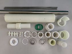
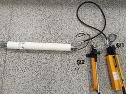
The three-dimensional light curing technology was used to process the test tooling, such as reserved appropriate clearance and shell pulling to ensure smooth installation, cut part of the cavity to make it exposed for easier observation, etc.
The processed parts are shown in Figure 14, and the assembled hydraulic decoder is shown in Figure 15.
|
|
| Fig 14. Components of hydraulic decoder | Fig 15. Hydraulic decoder after assembly |
The movement of the layer selection structure was completed by alternating pressure of two hand pumps. First, slowly pressurized by pump 2, at this time, it was observed that the layer selection structure rotated slowly and moved forward, and the guide rod was inserted into the two position two-way valve of control layer 1 until the guide rod no longer moved. At this time, relieved the pressure on pump 2, under the action of the return spring, the guide rod moved backward for a certain distance, and then stopped moving. At this time, closed the lower pipeline of the decoder connected to layer 1 (hereinafter referred to as pipeline 1), slowly pressurized pump 1, and if it was found that the guide rod cannot move, it was proved that the self-locking structure had locked the layer selection structure. Open pipeline 1, and it was found that hydraulic oil flows out, which proved that the two-way valve of layer 1 had been turned on.
Closed the pipeline 1 and slowly pressurized the pump 2 again. It was found that the guide rod moved forward again for a certain distance, and then stopped moving, at this time, the pressure of pump 2 was relieved and pump 1 was slowly pressurized. The guide rod rotated slowly and moved backward under the action of the return spring and pump 1 until it stopped moving, which proved that the reset of the layer selection structure was successful.
Continued to repeat the above operations, the four layers could be successfully selected and reset, and the pipelines of the corresponding layers had hydraulic oil flowing out, which proved that the control strategy, layer selection, self-locking and reset functions of the decoder meat the requirements of the expected design.
5. Conclusion
According to the development status and requirements of intelligent well completion technology, aiming at controlling four layers in the well by controlling a single hydraulic decoder with two hydraulic control pipelines above the well, this paper designed the structure of the hydraulic decoder, simulated and analyzed its performance, and verified its working principle by experiments. The main research contents and conclusions are as follows:
(1) The downhole single hydraulic decoder was controlled by two hydraulic pipelines on the well, and the ICV of four layers was controlled by the combination of hydraulic drive and mechanical movement. The motion equation of the layer selection structure of the hydraulic decoder was established with 4 MPa as the unlocking pressure.
(2) The dynamic simulation analysis of hydraulic decoder was carried out by ADAMS software. The results show that the motion of the sliding sleeve inside the decoder was normal, and the layer selection, locking and unlocking functions can be realized. When selecting the layer, the sliding sleeve started to move around 55 s, the maximum velocity was 0.00648 m / s, the maximum acceleration was 0.072 m / s2, the maximum velocity was 0.009 m / s, and the maximum acceleration was 0.092 m / s2. The positions with large velocity changes appear in the linear motion part of the anti-cylindrical cam and the impact force generated during the movement was small, and the structure design was reasonable.
(3) The prototype of the hydraulic decoder was processed by stereo light curing 3D printing equipment, and the reliability of the hydraulic decoder structure was verified. The results showed that the layer selection structure can realize the selection and reset of the corresponding layer, and the self-locking structure can lock the layer selection structure and unlock it. During the movement, there was no mutual interference and stuck between the sliding sleeves.
Acknowledgement
This research is supported by China University of Petroleum (East China).
Reference
[1] ZHANG Yanting, HUANG Zheng, ZHANG Hao, XU Jingyu, WANG Lin, QI Yaoguang, YUAN Xiang, YU Yangyang EGS combined mining technology based on downhole decoder [j] Journal of China University of Petroleum (NATURAL SCIENCE EDITION), 2021,45 (03): 111-117.
[2] YANG Yingna Research on the fluid control system between intelligent wells [d] Xi'an: Xi'an Petroleum University, 2013.
[3] Arashi Ajayi, Shawn Pace, Rryan Petrich. Managing Operational Challenges in the Installation of Intelligent Well Completion in a Deepwater Environment[R]. SPE116133, 2008.
[4] Halliburton. IntervalControl[EB/OL]. http://www. halliburton.com/ps/default.aspx?navid=1317&pageid=2606&prodgrpid=PRG%3a%3aK4DII5E8Z, 2011.
[5] ZHANG Fenghui, XUE Dedong, XU Xingan, ZHANG Jieru Research on Key Technologies of intelligent downhole hydraulic control system for well completion [j] Petroleum mining machinery, 2014,43 (11): 7-10.
[6] GUO Dong Parametric design and analysis of intelligent well downhole flow controller [d] Chengdu: Southwest Petroleum University, 2018.
[7] ZHANG Yang Research and design of hydraulic monitoring system for intelligent well downhole flow controller [d] Chengdu: Southwest Petroleum University, 2018.
[8] ZHAO Kang Integrated design and analysis of intelligent well downhole flow controller [d] Chengdu: Southwest Petroleum University, 2017.
[9] JIA Liting Research and analysis of downhole inflow control valve of intelligent well [d] Chengdu: Southwest Petroleum University, 2015.
[10] LI Pengfei Research on intelligent well downhole flow control system [d] Qingdao: China University of Petroleum (East China), 2017.
[11] XU Furen Calculation of friction caused by O-ring [j] Petroleum machinery, 1989 (08): 9-10+35.
Document information
Published on 14/04/23
Accepted on 06/04/23
Submitted on 27/02/23
Volume 39, Issue 2, 2023
DOI: 10.23967/j.rimni.2023.04.002
Licence: CC BY-NC-SA license
Share this document
claim authorship
Are you one of the authors of this document?


