| Line 477: | Line 477: | ||
==References== | ==References== | ||
| + | <div class="auto" style="text-align: left;width: auto; margin-left: auto; margin-right: auto;font-size: 85%;"> | ||
| − | [1] M. | + | [1] Aubertin M., Li L., Arnoldi S., Belem T., Bussière B., Benzaazoua M., Simon R. Interaction between backfill and rock mass in narrow stopes. Soil and rock America, 1:1157-1164, 2003. |
| − | [2]B. | + | [2] Bussière B. Colloquium 2004: hydro-geotechnical properties of hard rock tailings from metal mines and emerging geo-environmental disposal approaches. Canadian Geotechnical Journal, 44(9):1019-1052, 2007. |
| − | [3]M. | + | [3] Benzaazoua M., Bussière B., Demers I., Aubertin M., Fried É., Blier A. Integrated mine tailings management by combining environmental desulphurization and cemented paste backfill: application to mine Doyon, Quebec, Canada. Miner. Eng., 21(4):330-340, 2008. |
| − | [4] | + | [4] Udias A., Pistocchi A., Vigiak O., Grizzetti B., Bouraoui F., Alfaro C. ESPRES: A web application for interactive analysis of multiple pressures in aquatic ecosystems, Science of the Total Environment, 744: 140792, 2020. |
| − | [5]C. | + | [5] Falagan C., Grail B.M., Johnson D.B. New approaches for extracting and recovering metals from mine tailings. Miner. Eng., 106:71-78, 2017. |
| − | [6]C. | + | [6] Qi C., Fourie A., Chen Q., Tang X., Zhang Q., Gao R. Data-driven modelling of the flocculation process on mineral processing tailings treatment. J. Cleaner Prod., 196:505-516, 2018. |
[7]Q. Chen, Q. Zhang, C. Qi, A. Fourie, C. Xiao, Recycling phosphogypsum and construction demolition waste for cemented paste backfill and its environmental impact, J. Cleaner Prod. 186(2018)418-429. | [7]Q. Chen, Q. Zhang, C. Qi, A. Fourie, C. Xiao, Recycling phosphogypsum and construction demolition waste for cemented paste backfill and its environmental impact, J. Cleaner Prod. 186(2018)418-429. | ||
| Line 567: | Line 568: | ||
[45]S. Cao, E. Yilmaz, W. Song, G. Xue, Loading rate effect on uniaxial compressive strength behavior and acoustic emission properties of cemented tailings backfill, Constr. Build. Mater. 213(2019)313-324. | [45]S. Cao, E. Yilmaz, W. Song, G. Xue, Loading rate effect on uniaxial compressive strength behavior and acoustic emission properties of cemented tailings backfill, Constr. Build. Mater. 213(2019)313-324. | ||
| + | </div> | ||
Revision as of 15:06, 14 April 2021
Abstract
Backfill is widely used in underground mines around the world for its effective reduction in environmental impact of mining operations by utilizing a part of mine waste as underground backfill material. The strength of backfill plays a critical role in improving stop stability and preventing surface subsidence. In this paper, a series of SHPB (Split Hopkinson Pressure Bar) tests with different strain rates and static axial pressures are conducted. The results show that: (1) The dynamic strength of the backfill specimen increases first and then decreases with the increase of static axial pressure. It reaches a maximum when the static axial pressure reaches 30% of the static compressive strength in the SHPB test. (2) The stress-strain curves of backfill specimens can be divided into three stages: elastic stage, yield stage and failure stage. The compaction stage is obscure. The backfill specimens are not sensitive at low strain rate. (3) With the increase of incident energy, the absorbed energy mounts. (4) The failure mode of the backfill specimen is tensile failure when static axial pressure is 0MPa in the SHPB test while it becomes compression shear failure when static axial pressure is higher than 0MPa. (5) The backfill specimen is very compressed when it is loaded with axial stress and confining stress simultaneously. This compression property of backfill specimen may be related to the nature of hydration products at different curing times, which requires further research in the future.
Keywords: Backfill, coupled static and dynamic loads, dynamic strength, deformation feature, energy transfer principle, failure mode
1. Introduction
Backfill is widespread used in underground mines due to its effective decrease in environmental impact of mining operations with the help of underground backfill material [1-4]. With low economic values, mining wastes (mainly tailings) take up large areas of land to store [5], leading to soil pollution, which can be solved by making them backfill materials [6-8]. Moreover, they can also improve stope stability and prevent surface subsidence [9-11].
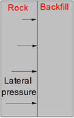
The strength of backfill is the key to improve stope stability and prevent surface subsidence [12,13]. The strength of backfill is constantly changing due to such factors as curing age and composition [14-16]. At present, nearly all studies on the mechanical properties of backfill mainly focus on the statics properties [17-19]. For example, Shuai Cao conducted numerous uniaxial compression experiments and defined the strength reduction coefficient [20]. Alireza indicated the basic characteristics of backfill mechanics [21,22]. The effect of temperature and different aggregates on the early compressive strength of backfill is investigated by Nasir and Fall [23]. Furthermore, the mixing time may also affect the compressive strength of backfill [24,25], which changes with the variation in rate of loading. The compressive strength of the backfill increases with increasing loading rate [26,27]. Some scholars also conducted experiments such as creep, loading and unloading, stress-seepage coupling to investigate the characteristics of backfill mechanics [28-32]. These research results mainly focus on the statics properties. The stability of backfill is also affected by earthquakes, blasts, and rock bursts. However, there are a few research carried out about the dynamic properties. Only a few scholars have conducted relevant research. For example, Dong [33] conducted an on-site blasting vibration test and studied the damage principle of backfill at blasting vibration. Xiang Zhi et al. analyzed the deformation and damage characteristics of different proportions of backfill [34]. Shuai Cao investigated dynamic responses of backfill at SHPB compression load [35]. Liu et al. [36] analyzed the dynamic responses of it made of superfine tailings. The damage characteristics and dynamic responses have been analyzed. However, the lateral pressure has not been considered by these researchers. Figure 1 shows the backfill in underground stope. The backfill withstand lateral pressure caused by the backfill gravity and varied with different heights. Therefore, the strength, damage characteristics and dynamic responses of backfill will be different at different heights under lateral pressure, which requires further research.
There are many studies on the static mechanics of backfill, but few researches on the dynamic characteristics of backfill. It is of great significance to carry out the research on its dynamic characteristics. Accurately grasping the dynamic characteristics of backfill has important theoretical significance and engineering value for improving the stope stability and preventing surface subsidence. In this paper, the backfill is taken as the research object. With different strain rates and axial pressures used to replace the lateral pressure, a series of SHPB (Split Hopkinson Pressure Bar) tests were conducted. Analyses were made in such aspects as the deformation characteristics, strength, principle of energy transfer, failure mode of backfill at one-dimensional dynamic and static combination loading.
|
| Figure 1. The backfill in underground stope |
2. Materials and methods
2.1 Specimen preparation
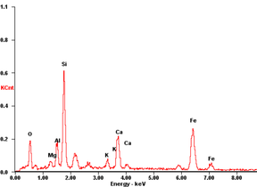
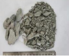
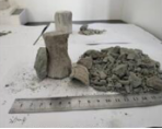
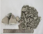
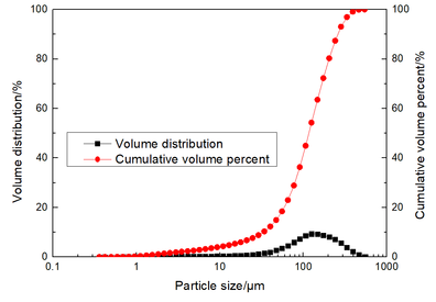
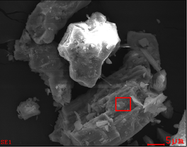
Backfill specimens are composed of ordinary Portland cement P.O. 32.5, tap water, and classifying tailings. The tailings are iron tailings. The particle size distribution of the classifying tailings is shown in Figure 2. The cumulative content of fine particles () is 6.49% which is up to the quality standards. In addition, the content of clay particles () is 2.65% which has little impact on the quality of backfill specimens. The microstructure and microanalysis of tailings are provided in Figure 3. The tailings surface is coarse that facilitates the formation of voids. The elements composition of the tailings are shown in Table 1 where SiO2 is the most dominant mineral in the iron tailings. Moreover it also contains some Al2O3 and Fe3O4. The chemical components of Portland cement P.O. 32.5 are shown in Table 2.
|
| Figure 2. The particle size distribution of the tailings |
|
|
| Figure 3. The microstructure and microanalysis of tailings | |
| Element | Wt% | At% |
|---|---|---|
| O | 16.23 | 31.69 |
| Mg | 2.11 | 2.71 |
| Al | 6.00 | 6.95 |
| Si | 24.01 | 26.71 |
| K | 2.49 | 1.99 |
| Ca | 11.18 | 8.72 |
| Fe | 37.98 | 21.25 |
| Varieties/% | P.O.32.5 |
|---|---|
| SiO2 | 21.36 |
| O3 | 3.21 |
| O3 | 4.92 |
| MgO | 3.41 |
| CaO | 62.33 |
| SO3 | 1.92 |
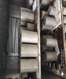
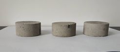
The ratio of cement to tailings is 1:4 and the concentration is 75%. The molds ( mm) are used to make specimens. As shown in Figure 4, the prepared specimens are placed in a HY-40A cement standard curing box for curing 14 d. The mm specimens are cut and polished as Figure 5.
|
| Figure 4. Maintenance of backfill specimens |
|
| Figure 5. The backfill specimens for SHBP test |
2.2 SHPB tests equipment
Split Hopkinson pressure bars (SHPBs) are widely used to investigate the dynamic characteristics of different materials of which most of them are concrete and rock materials [37,38]. There is an extensive application about this method [39-43]. The SHPB device needed in the tests is shown in Figure 6 while the schematic view of it is shown in Figure 7. With various axial pressure and confining pressure, the SHPB device is able to apply different dynamic loads to specimens, which is a prerequisite for the tests. The bullet, transmission rod and incident rod used in this device are all made of 45GrNiMoVA alloy steel with high strength. The diameter, elastic modulusis, Poisson's ratio and density are respectively 50mm, 206GPa, 7800Kg/m3, and 0.27. Beyond all that, the lengths of the transmission rod, the incident rod, and the bullet are 1.50m, 2.00m, 0.50m and 0.36m, respectively. Special-shaped bullet is used in the launch cavity to reduce PC oscillation and meet the requirements of half-sine wave loading. Ultra dynamic strain gauge is used for collecting data while DL-750 oscilloscope for displaying waveform and JXCS-02 chronograph for timing.

|
| Figure 6. The SHBP device |

|
| Figure 7. The schematic view of SHPB device |
2.3 Principle of combined dynamic and static loading
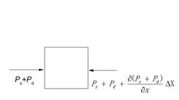
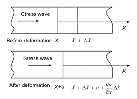
Figure 8 shows the deformation and stress in the elastic rod at combined loads. With the density and elastic modulus of the cylindrical rod unchanged, the yield strength of axial load is less than that of elastic rod. Assuming that the length-to-diameter ratio of the elastic rod is large enough and the cross section of the rod is always flat when the dynamic load being loaded, the relationship between the deformation and force of the micro-element under the combination of Pas and Pd can be obtained as equation (1)
|
(1) |
where is the density of the elastic rod, is the cross-sectional area of the elastic rod, is the displacement of the micro-element at the after the force being loaded.
According to the definition of stress, strain and Hook's law, we can get equations (2)-(4)
|
(2) |
|
(3) |
|
(4) |
The axial load remains constant throughout the length direction
|
(5) |
Equation (6) can be obtained from equations (1)-(5)
|
(6) |
The equation (6) is the same as the classical one-dimensional wave equation, which shows that the one-dimensional stress wave theory is also suitable for elastic rods and specimens at combined dynamic and static loading [44].
|
|
| (a) Elastic rod deformation during loading | (b) Deformation of microelements during loading |
| Figure 8. Principle of test coupled static and dynamic loads | |
3. Results
3.1 Strength analysis
First, the static load test of the backfill specimens is conducted. The uniaxial compressive strength of the backfill specimens is measured and shown in Table 3.
| Number | Uniaxial compressive strength(MPa) | Average(MPa) |
|---|---|---|
| 1 | 3.54 | 3.56 |
| 2 | 3.35 | |
| 3 | 3.62 | |
| 4 | 3.72 |
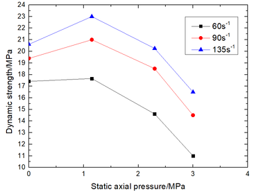
Figure 9 shows the dynamic strength of the backfill specimens under different static axial pressure. It can be seen that the dynamic strength of the backfill specimen is higher than the static uniaxial compressive strength. Moreover, with the increase of static axial pressure, the dynamic strength rises first and then decreases. The loaded stress wave will be reflected at the crack inside the backfill specimen and a tensile wave will be generated to expand the crack as the test is conducted. When a small static axial load is applied, the cracks inside the backfill specimen are compacted . Therefore, the dynamic strength of the backfill specimen rises with the increase of static axial pressure first. When the static axial pressure keeps mounting, damage occurs inside the backfill specimen and new cracks are generated. The stress wave generates a tensile wave within new and old crack, resulting in further crack extension and reduction of dynamic strength of the backfill specimen.
|
| Figure 9. The dynamic strength of the backfill specimens under different static axial pressure |
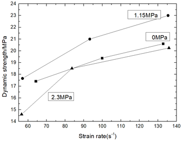
Figure 10 shows the dynamic strength of the backfill specimens at different strain rates. It can be observed that the dynamic strength mounts with the increase of strain rate under different axial pressures.
|
| Figure 10. The dynamic strength of the backfill specimens at different strain rates |
3.2 Deformation characteristics
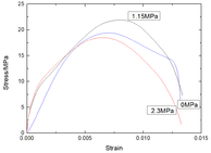
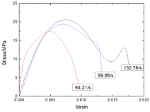
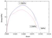
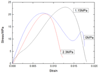
Figure 11 shows stress-strain curves of backfill specimens under different static axial pressure. Except the obscure compaction stage, it can be divided into three stages: elastic stage, yield stage and failure stage.
|
| |
| (a) Static axial pressure is 0 | (b) Static axial pressure is 1.15MPa | (c) Static axial pressure is 2.30MPa |
| Figure 11. Stress-strain curves of backfill specimens at different static axial pressure | ||
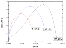
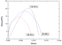
Figure 12 shows stress-strain curves of backfill specimens at similar strain rate. The curve paths of the stress-strain curves in the elastic phase are basically same when the strain rate is about 60 s-1. When the strain rate increases by 90s-1 and 135s-1, a significant change occurs, which indicates that the backfill specimens are not sensitive at low strain rate.
|
| |
| (a) Strain rate is about 60s-1 | (b) Strain rate is about 90s-1 | (c) Strain rate is about 135s-1 |
| Figure 12. Stress-strain curves of backfill specimens at similar strain rate | ||
3.3 Principle of energy transfer
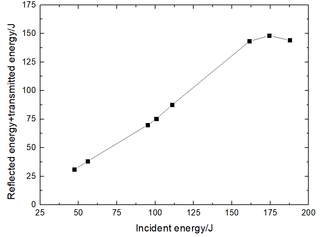
Figure 13 shows relationship of sum of transmitted energy with incident energy. What can be concluded that the sum of reflected energy and transmitted energy first increase continuously with the increasing incident energy, and then stabilize gradually.
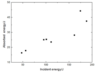
Figure 14 demonstrates the relationship of absorbed energy with incident energy. The absorbed energy increases with incident energy and the increase speed keeps accelerating after reaching a certain level.
|
| Figure 13. Relationship of sum of transmitted energy with reflected energy and incident energy |
|
| Figure 14. Relationship between absorbed energy and incident energy |
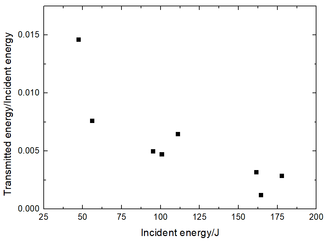
Figure 15 shows the relationship of ratio of transmitted energy to incident energy vs. incident energy. A result can be drawn that the ratio of transmitted energy to incident energy decreases with the increase of incident energy, indicating that the increment of transmission energy decreases gradually for the reason that most of the energy is absorbed to destroy the backfill specimen when the incident energy increases.
|
| Figure 15. Relationship of ratio of transmitted energy to incident energy vs. incident energy |
3.4 Failure Mode
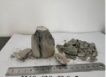
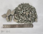
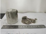
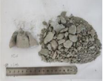
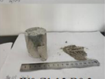
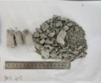
Figures 16, 17 and 18 show the failure modes of the backfill specimens when the static axial pressure is 0MPa, 1.15MPa and 2.30MPa at different strain rates. Figure 16 indicates that the backfill specimens form a fracture surface parallel to the longitudinal direction of the it. It is lateral tensile failure when static axial pressure is 0MPa in the SHPB test. Figures 17 and 18 indicate that the failure modes are compression shear failure when static axial pressure is 1.15MPa or 2.3MPa in the SHPB test.
|
|
| (a) Strain rate is around 60s-1 | (b) Strain rate is around 90s-1 |
| |
| (c) Strain rate is around 135s-1 | |
| Figure 16. Failure modes of backfill specimens when static axial pressure is 0MPa in the SHPB test | |
|
|
| (a) Strain rate is around 60s-1 | (b) Strain rate is around 90s-1 |
| |
| (c) Strain rate is around 135s-1 | |
| Figure 17. Failure modes of backfill specimens when static axial pressure is 1.15MPa in the SHPB test | |
|
|
| (a) Strain rate is around 60s-1 | (b) Strain rate is around 90s-1 |
| |
| (c) Strain rate is around 135s-1 | |
| Figure 18. Failure modes of backfill specimens when static axial pressure is 2.30MPa in the SHPB test | |
4. Discussion
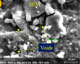
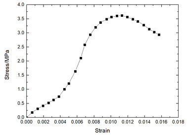
Most backfill is composed of tailings and cement. The surface of the tailings particles is coarse and is shown in Figure 3. Figure 19 evidently shows that the voids are easily formed between tailings particles and they will lead to compressibility of backfill specimen [45]. Therefore, there is a compression phase stress-strain curve of backfill specimens at static loading as shown in Figure 20. The stress reaches about 30% of the peak stress, when the compression phase ends. At this point, the stress is about 1.15MPa, which gives an explanation why the dynamic strength of backfill specimen is greatest when static axial pressure is 1.15MPa in the SHPB test. With the backfill specimens compressed, the voids inside the specimens become smaller and then the cracks consisting of voids are closed. The reflection effect of stress wave on crack is reduced and the dynamic strength of backfill specimen increases. If the static axial pressure continues to increase, new cracks will occur while the dynamic strength of the backfill specimen will decrease.
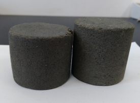
The backfill specimen is greatly compressed when it is loaded with axial stress and confining stress simultaneously in the SHBP test. The result is shown in Figure 21. It can be seen that the backfill specimen is not destroyed at high strain rates in the SHBP test. It would be destroyed, if the rock was compressed like the backfill specimen in Figure 21. This compression property of the backfill specimen may be related to the nature of the hydration products at different curing times. It requires further research in the future.
|
| Figure 19. The microstructure of backfill specimen |
|
| Figure 20. Stress-strain curve of backfill specimens cured for 14 days at static loading |
|
| Figure 21. The compressed backfill specimen |
Figure 11 shows stress-strain curves of backfill specimens under different static axial pressure. It can be divided into three stages: elastic stage, yield stage and failure stage. The compaction stage is not obvious. The backfill specimen deforms immediately when the static axial pressure is 0MPa. There is no obvious compression phase due to an instant compaction of the internal micro-cracks. When a certain static axial pressure is loaded, the micro-cracks inside the backfill specimen have been compacted, so there is also no compression phase. The initial phase of the stress-strain curve is approximately a straight line, which is in line with Hooke's law. This phase is so called elastic phase. Then, the stress-strain curve shifts, resulting from the failure of backfill specimen, the rapid expansion of the crack, and the decrease in the compression rate. At this point, the backfill specimen undergoes plastic deformation, that is to say, the yield phase. With the expansion and penetration of micro-cracks, dominant cracks are generated inside the backfill specimen. Then macro-damage occurs, known as the failure phase. The nature of the hydration product may explain why the backfill specimens are not sensitive at low strain rate, which requires further research.
The incident energy increases with the increasing strain rate while the absorbed energy increases with incident energy. The speed increase is accelerated before reaching a certain level. Because most of the energy is absorbed to destroy the backfill specimen.
The backfill specimen generates lateral tensile failure when static axial pressure is 0MPa in the SHPB test. It form a fracture surface parallel to the longitudinal direction of the backfill specimens and it generates tensile failure along the longitudinal direction under the influence of Poisson effect. The broken block size of backfill specimen becomes smaller and its quantity mounts when the strain rate increases. However, it can still be observed from the shape of the fragment that the fracture surface is mainly parallel to the length direction of the backfill specimen. What can be concluded that it is still lateral tensile failure. The failure mode is compression shear failure when static axial pressure is 1.15MPa or 2.3MPa in the SHPB test. Before the occurrence of stress concentration, the ends of specimen generate end effects at the static axial pressure. A compression zone is formed at both ends of the specimen. Potential shear failure surface occurs inside the specimen. The crack will propagate along the potential shear failure surface when dynamic load is applied. Eventually a macro damage surface is formed, as shown in Figures 17 and 18. The application of static axial pressure has a significant influence on the failure mode of backfill specimen. However, the failure modes of backfill specimens all belong to compression shear failure with the static axial pressure applied. The magnitude of static axial pressure only works in the fragmentation of backfill specimens.
5. Conclusion
- The dynamic strength of the backfill specimen increases first and then decreases with the increase of static axial pressure. It becomes the maximal when the static axial pressure reaches 30% of the static compressive strength in the SHPB test. Besides, it increases with the increasing strain rate under different axial pressures.
- The stress-strain curves of backfill specimens can be divided into three stages: elastic stage, yield stage and failure stage. The compaction stage is not obvious. In addition to, the backfill specimens are not sensitive at low strain rate.
- The sum of reflected energy and transmitted energy first increases continuously with the increase of incident energy, and then stabilizes. The absorbed energy increases with the increase of incident energy and the speed increase is accelerated after reaching a certain extent.
- The failure mode belongs to tensile failure when static axial pressure is 0MPa while it transforms into compression shear failure when static axial pressure is higher than 0MPa in the SHPB test.
- With backfill specimen loaded with axial stress and confining stress simultaneously, the backfill specimen will be compressed greatly. This compression property of the backfill specimen may be related to the nature of the hydration products at different curing times. It requires further research in the future.
This research was mainly supported by National Key Technologies Research & Development Program (2017YFC0804609) and the National Natural Science Foundation of China (51774137).
References
[1] Aubertin M., Li L., Arnoldi S., Belem T., Bussière B., Benzaazoua M., Simon R. Interaction between backfill and rock mass in narrow stopes. Soil and rock America, 1:1157-1164, 2003.
[2] Bussière B. Colloquium 2004: hydro-geotechnical properties of hard rock tailings from metal mines and emerging geo-environmental disposal approaches. Canadian Geotechnical Journal, 44(9):1019-1052, 2007.
[3] Benzaazoua M., Bussière B., Demers I., Aubertin M., Fried É., Blier A. Integrated mine tailings management by combining environmental desulphurization and cemented paste backfill: application to mine Doyon, Quebec, Canada. Miner. Eng., 21(4):330-340, 2008.
[4] Udias A., Pistocchi A., Vigiak O., Grizzetti B., Bouraoui F., Alfaro C. ESPRES: A web application for interactive analysis of multiple pressures in aquatic ecosystems, Science of the Total Environment, 744: 140792, 2020.
[5] Falagan C., Grail B.M., Johnson D.B. New approaches for extracting and recovering metals from mine tailings. Miner. Eng., 106:71-78, 2017.
[6] Qi C., Fourie A., Chen Q., Tang X., Zhang Q., Gao R. Data-driven modelling of the flocculation process on mineral processing tailings treatment. J. Cleaner Prod., 196:505-516, 2018.
[7]Q. Chen, Q. Zhang, C. Qi, A. Fourie, C. Xiao, Recycling phosphogypsum and construction demolition waste for cemented paste backfill and its environmental impact, J. Cleaner Prod. 186(2018)418-429.
[8]H. Lu, C. Qi, Q. Chen, D. Gan, Z. Xue, Y. Hu, A new procedure for recycling waste tailings as cemented paste backfill to underground stopes and open pits, J. Cleaner Prod. 188(2018)601-612.
[9]D.A. Landriault, Paste backfill mix design for Canadian underground hard rock mining. in: Proc. of the 97th Annual General Meeting on the Rock Mechanics and Strata Control, Halifax, Canada, pp(1995)1-8.
[10]F.P. Hassani, J. Ouellet, M. Hossein, Strength development in underground high sulphate paste backfill operation, CIM Bullet. 94(2001)57-62.
[11]T. Belem, M. Benzaazoua, An overview on the use of paste backfill technology as a ground support method in cut-and-fill mines. Proc. of the 5th International Symposium on Ground Support in Mining and Underground Construction, Perth, Australia, pp(2004)637-650.
[12]L. Li, M. Aubertin, An improved method to assess the required strength of cemented backfill in underground stopes with an open face, Int. J. Min. Sci. Technol. 24 (4)(2014)549-558.
[13]S. Cao, C. Du, Y. Tan, J. Fu, Mechanical model analysis of consolidated filling pillar using stage-delayed backfilling in metal mine, Rock Soil Mech. 36 (8)(2015)2370-2376.
[14]M. Fall, M. Benzaazoua, Modeling the effect of sulphate on strength development of paste backfill and binder mixture optimization, Cement Concrete Res. 35(2)(2005)301-314.
[15]K.M. Skarzyn, Reuse of coal mining wastes in civil engineering—Part 2:Utilization of minestone, Waste Manage. 15 (2)(1995)83-126.
[16]L. Orejarena, M. Fall, The use of artificial neural networks to predict the effect of sulphate attack on the strength of cemented paste backfill, B. Eng. Geol. Environ. 69(4)(2010)659-670.
[17]C. Qi, A. Fourie, Q. Chen, Q. Zhang, Strength prediction model using artificial intelligence for recycling waste tailings as cemented paste backfill, J. Cleaner Prod. 183(2018)566-578.
[18]K. Babak, K. Ahmed, B. Tikou, B. Bruno, B. Hassan, Experimental investigation of mechanical and microstructural properties of cemented paste backfill containing maple-wood filler, Constr. Build. Mater. 121(2016)222-228.
[19]H. Jae, H. Seung, K. Shiho, J.Y. Hong, Rheology of cement paste under high pressure, Cem. Concr. Compos. 77(2017)60-67.
[20]S. Cao, W. Song, G. Xue, Test of strength reduction of cemented tailings filling considering layering character, Rock and Soil Mechanics. 36(10)(2015)2869-2876.
[21]A. Ghirian, M. Fall, Coupled thermo-hydro-mechanical-chemical behavior of cemented paste backfill in column experiments. Part I: Physical and thermal processes and characteristics, Eng. Geol. 164(2013)195-207.
[22]A. Ghirian, M. Fall, Coupled titiermos-hydro-mechanical-chemical behaviour of cemented paste backfill in column experiments part II:Mechanical,chemical and microstructural processes and characteristics, Engineering Geology. 170(2014)11-23.
[23]O. Nasir, M. Fall, Coupling binder hydration,temperature and compressive strengh development of underground cemented paste backfill at early ages, Tunnelling and Underground Space Technology 25(2010)9-20.
[24]K. Takahashi, T.A. Bier, T. Westphal, Effects of mixing energy on technological properties and hydration kinetics of grouting mortars, Cem. Concr. Res. 41 (11)(2011)1167-1176.
[25]M. Yang, H.M. Jennings, Influences of mixing methods on the microstructure and rheological behavior of cement paste, Adv. Cem. Based Mater. 2 (2)(1995)70-78.
[26]Y. Li, L. Jin, L. Zhang, Mechanical parameters of cemented paste backfilling and its failure modes under different loading rates, Electron. J. Geotech. Eng. 21 (3)(2016)969-978.
[27]A. Ghirian, M. Fall, Coupled tiiermos-hydro-mechanical-chemical behaviou of cemented paste backfill in column experiments part I:Physical,hydraulic and thermal processes and characteristics, Engineering Geology. 164(2013)195-207.
[28]M. Pokharel, M. Fall, Combined influence of sulphate and temperature on the saturated hydraulic conductivity of hardened cemented paste back, Cement&Concrete Composites. 38(2013)21-28.
[29]D. Wu, S. Cai, G. Huang, Coupled effect of cement hydration and temperature on rheological properties of fresh cemented tailings backfill slurry, Transactions of Nonferrous Metals Society of China 12(2014)2954-2963.
[30]M. Fall, M. Pokharel, Coupled effects of sulphate and temperature on the strength development of cemented filings backfills:Portland cement paste backfill, Cement&Concrete Composites 32(2010)819-828.
[31]M. Fall, J.C. Celestin, A contribution to understanding the effects of curing temperature on the mechanical properties of mine cemented tailings backfill, Engineering Geology. 114(2010)397-413.
[32]N. Abdu-Hussain, M. Fall, Thermo-hydro-mechanical behaviour of sodiumsilicate-cemented paste tailings in column experiments, Tunnelling and Underground Space Technology 29(2012)85-93.
[33]K.C. Dong, Research on the Influence and Control Techniques of Blasting Seismic Wave on Backfill, Central South University. Changsha, China 2010.
[34]Z. Li, X. Li, On damage model of cemented tailings backfill and its match with rock mass, Rock and Soil Mechanics. 27(9)(2006)1442-1446.
[35]S. Cao, E. Yilmaz, W. Song, Dynamic response of cement-tailings matrix composites under SHPB compression load, Constr. Build. Mater. 186(2018)892-903.
[36]B. Liu, Y. Gao, A. Jin, X. Wang, Dynamic characteristics of superfine tailings-blast furnace slag backfill featuring filling surface, Constr. Build. Mater. 242(2020)118-173.
[37]Q. Zhang, J. Zhao, A review of dynamic experimental techniques and mechanical behaviour of rock materials, Rock Mech. Rock Eng. 47 (4)(2014)1411-1478.
[38]J.W. Tedesco, C.A. Ross, Strain-rate-dependent constitutive equations for concrete, ASME J. Press. Vessel. Technol. 120 (4)(1998)398-405.
[39]X. Li, Z. Zhou, T. Lok, L. Hong, T.B. Yin, Innovative testing technique of rock subjected to coupled static and dynamic loads, Int. J. Rock Mech. Min. Sci. 45 (5)(2008)739-748.
[40]Y. Wei, Z.G. Lu, K. Hu, X. Li, P. Li, Dynamic response of ceramic shell for titanium investment casting under high strain-rate SHPB compression load, Ceram. Int. 44(2018)11702-11710.
[41]Y. Gao, J. Xu, E. Bai, X. Luo, J. Zhu, L.X. Nie, Static and dynamic mechanical properties of high early strength alkali activated slag concrete, Ceram. Int. 41(2015)12901-12909.
[42]L. Li, W.G. Guo, X. Yu, D.X. Fu, Mechanical behavior of ceramic-metal joint under quasi-static and dynamic four point bending: microstructures, damage and mechanisms, Ceram. Int. 43(2017)6684-6692.
[43]Y. J. Xie, Q. Fu, K. Zheng, Q. Yuan, H. Song, Dynamic mechanical properties of cement and asphalt mortar based on SHPB test, Constr. Build. Mater. 70(2014)217-225.
[44]X. Li, F. Gong, J. Zhao, Test study of impact failure of rock subjected to one-dimensional coupled static and dynamic loads, Chinese Journal of Rock Mechanics and Engineering. 29(2)(2010) 251-260.
[45]S. Cao, E. Yilmaz, W. Song, G. Xue, Loading rate effect on uniaxial compressive strength behavior and acoustic emission properties of cemented tailings backfill, Constr. Build. Mater. 213(2019)313-324.
Document information
Published on 28/04/21
Accepted on 06/04/21
Submitted on 02/12/20
Volume 37, Issue 2, 2021
DOI: 10.23967/j.rimni.2021.04.002
Licence: CC BY-NC-SA license
Share this document
Keywords
claim authorship
Are you one of the authors of this document?
