Liuyang2017 (talk | contribs) (Created page with "<!-- metadata commented in wiki content <div class="center" style="width: auto; margin-left: auto; margin-right: auto;"> <big>Research on 3D Elastoplastic Seismic Performanc...") |
Liuyang2017 (talk | contribs) (Tag: Visual edit) |
||
| Line 76: | Line 76: | ||
'''Figure 3'''. Rotation angle of plastic hinge </div> | '''Figure 3'''. Rotation angle of plastic hinge </div> | ||
| − | rotation angle [[Image:Draft_Liu_754106674-image6.png| | + | rotation angle [[Image:Draft_Liu_754106674-image6.png|48x48px]] , where L is the length of the plastic hinge. |
It is worth noting that the hinge behavior defined in this paper is rigid and plastic, and the hinge has no elastic behavior, that is, if it is loaded or unloaded before yielding, there is no deformation in the hinge. When the frame element exhibits plastic behavior, all plastic deformation occurs in the hinge, while only elastic behavior occurs in other parts of the frame. | It is worth noting that the hinge behavior defined in this paper is rigid and plastic, and the hinge has no elastic behavior, that is, if it is loaded or unloaded before yielding, there is no deformation in the hinge. When the frame element exhibits plastic behavior, all plastic deformation occurs in the hinge, while only elastic behavior occurs in other parts of the frame. | ||
Revision as of 21:03, 4 September 2020
Abstract The special-shaped column structure system has more advantages than the rectangular column system in terms of architectural design and actual use. As a relatively new structural form, the concrete special-shaped column structure has not accumulated enough engineering practical experience. In this study, the rotation-moment curve of the plastic hinge of special-shaped column frame element was defined, the coupled PMM hinge applied to the frame element was studied, and the yield surface of the hinge was drawn. On this basis, an elastoplastic pushover analysis was conducted on a 12-storey special-shaped column frame model, its failure under different earthquakes was simulated, and its seismic performance was studied. The work of this article can provide reference for the engineering application of special-shaped column frame structure.
Keywords Special-shaped column frame, Seismic performance, Plastic hinge, Pushover method
1. Foreword
The concrete special-shaped column structure system is a structural system composed of special-shaped columns instead of rectangular cross-section columns as vertical support members. When the rectangular columns are arranged, they often make the room appear edges and corners, which affects the appearance, and at the same time reduces the use area of the room. The special-shaped column structure system avoids these problems and brings flexibility and convenience to architectural design and actual use[1-3].
The characteristics of special-shaped columns are more complex than those of ordinary rectangular columns. And due to the lack of structural seismic damage data, it is very necessary to study the seismic performance of special-shaped column structures.
2. Special-shaped column frame plastic hinge
2.1 Plastic deformation curve
The frame element has the effects of biaxial bending, torsion, and axial deformation. In this paper, the nonlinear analysis of the special-shaped column frame structure is realized by inserting plastic hinges in the frame elements. Each hinge represents a concentrated post-yield performance in one or more degrees of freedom. The hinge only affects the structural behavior in nonlinear static or dynamic analysis[4-6].
Each plastic hinge is simulated by a discrete point hinge. All plastic deformation, whether it is translation or rotation, occurs in the point hinge. The hinge length is generally a fraction of the element length, and is often of the same order of magnitude as the section height[7].
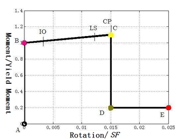
For each degree of freedom, a displacement-load curve can be defined to express the yield value and plastic deformation after yielding. This is achieved by a curve with five points A-B-C-D-E[6]. In the nonlinear analysis of the frame in this paper, the deformation curve of the plastic hinge is defined as follows:
In the Figure 2, the abscissa is the ratio of the frame element hinge rotation angle to the rotation angle scale factor SF. This article takes SF=1. The ordinate is the ratio of bending moment to yield bending moment. Point A is the origin, and point B represents yield. There is no deformation in the hinge before ascending to point B, only plastic deformation beyond point B will be revealed by the hinge. Point C represents the ultimate bearing capacity. Point D represents the residual strength. Point E represents complete failure .
The points IO (immediate use), LS (life safety) and CP (collapse prevention) are specified in the plastic curve. They can be reflected in the analysis results and can be used for performance-based design.
With reference to the specification FEMA-356 of Federal Emergency Management Agency in the United States[8], the coordinates of each point in the figure selected in this article are as follows: B(1, 0), C(1.1, 0.015), D(0.2, 0.015), E(0.2, 0.025). The rotation angles (ie, plastic deformation radian) corresponding to IO, LS, and CP are 0.003, 0.012, and 0.015 respectively.
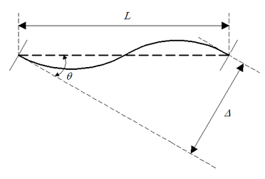
The definition of plastic hinge rotation angle is shown in the Figure 3[4].
rotation angle ![]() , where L is the length of the plastic hinge.
, where L is the length of the plastic hinge.
It is worth noting that the hinge behavior defined in this paper is rigid and plastic, and the hinge has no elastic behavior, that is, if it is loaded or unloaded before yielding, there is no deformation in the hinge. When the frame element exhibits plastic behavior, all plastic deformation occurs in the hinge, while only elastic behavior occurs in other parts of the frame.
2.2 Coupled PMM hinge
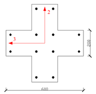
Generally speaking, the six degrees of freedom of a hinge are not coupled with each other. To simplify the calculation, this article specifies that the axial force / biaxial bending moment behavior of the hinge is coupled, which is also called P-M2-M3 or PMM hinge[6]. P is the axial force perpendicular to the cross section (pulling is positive), M2 is the bending moment around axis 2, and M3 is the bending moment around axis 3.
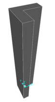
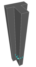
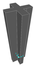
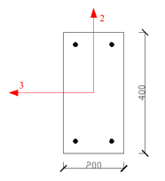
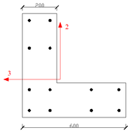
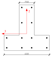
Figure 4 shows the cross section of the rectangular beam and special-shaped column to be analyzed in this paper. The intersection of axis 2 and axis 3 is the centroid of the section. The diameter of the longitudinal reinforcement of the special-shaped column is 16mm, and the diameter of the stirrup is 10mm and the spacing is 150mm. The diameter of the longitudinal reinforcement of the rectangular beam is 16mm, and the diameter of the stirrup is 6mm and the spacing is 150mm. The longitudinal reinforcement of the special-shaped column and rectangular beam adopts HRB335 steel bar, the stirrup adopts HPB300 steel bar, and the selected concrete strength grade is C30[9].
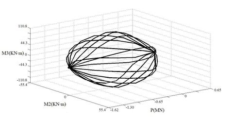
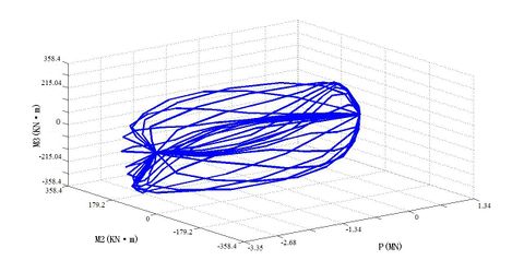
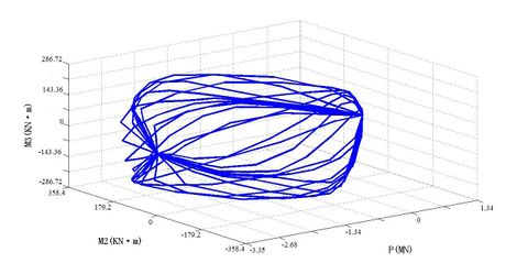
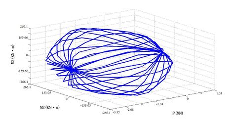
For PMM hinges, it specifically refers to the designation of a yield surface in the 3D P-M2-M3 space to represent the position where the different combinations of the axial force P, the secondary bending moment M2 and the main bending moment M3 yield first. This surface is designated as a set of P-M2-M3 curves. In this paper, with the help of finite element software SAP2000, the PMM yield surface of each frame element's plastic hinge is calculated, as shown in Figures 5 to 8.
3. Finite element model of special-shaped column frame
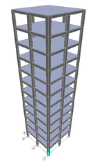
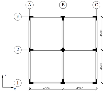
A typical 12-storey special-shaped column frame is selected as the calculation model in this paper. There is no rectangular column in the structure. As shown in Figure 9 and Figure 10, it has 2 spans along the X direction and 2 spans along the Y direction, each span is 4.5m. The layouts of the 12 storeys are the same, and the height of each storey is 2.9m. The nonlinear elastoplastic analysis of the frame structure is realized on the basis of inserting PMM hinges at the beam and column ends of the frame.
The elastic modulus of C30 concrete selected in this paper is 30 000MPa, its Poisson's ratio is 0.2, the standard value of axial compressive strength is 20.1MPa, and the standard value of axial tensile strength is 2.01MPa. The selected HRB335 steel bar has an elastic modulus of 200 000 MPa, a Poisson's ratio of 0.27, a standard value of yield strength of 335 MPa, and a tangent modulus of 2 000 MPa after yielding. The selected HPB300 steel bar has an elastic modulus of 210 000 MPa, a Poisson's ratio of 0.27, a standard value of yield strength of 300 MPa, and a tangent modulus of 2 000 MPa after yielding[9].
4. Seismic performance Analysis of special-shaped column frame
4.1 Pushover analysis method
Pushover analysis is one of the main methods of elastoplastic analysis of seismic structures. This article mainly applies the Pushover analysis method of inverted triangular distribution horizontal loading mode to calculate the seismic response of the structural model[11-14].
The seismic performance of the frame model under earthquakes with an intensity of 7, 8, and 9 degree is analyzed. According to "Code for Seismic Design of Buildings" (GB50011-2010), the corresponding relationship between seismic fortification intensity and design basic seismic acceleration is shown in Table 1[15].
| Seismic fortification intensity | 7 | 8 |
| Design basic seismic acceleration | 0.10(0.15)g | 0.20(0.30)g |
Taking the density of reinforced concrete as 2402.77kg/m3. Calculate the mass of the model and estimate the horizontal force (ie, base shear) under the action of the basic seismic acceleration corresponding to each seismic intensity, as shown in Table 2.
| Mass | 4.90×10⁵kg |
| 7degree (0.1g) | 480.2KN |
| 8degree (0.2g) | 960.4KN |
| 8degree (0.3g) | 1440.6KN |
4.2 Static pushover response of special-shaped column frame
With the help of SAP2000 software, the horizontal load is loaded in the X direction of the special-shaped column structure model, and the pushover calculation is carried out. The overall structure displacement and inter-storey displacement of the model under the action of earthquakes of various intensities are obtained. The local plastic deformation of the structure under different earthquakes is clearly reflected[16].
Take the uniform live load on each storey of the model as 3.0kN/m2, the representative value of the gravity load of the model is the sum of the structural self-weight and the combined value of the live load, and take the coefficient of the combined value of the uniform live load as 0.5. The model calculation is carried out in two load conditions: 1. Floor live load; 2. Structural self-weight and horizontal load. The analysis results of the framework model are as follows.
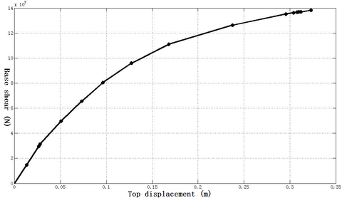
The top displacement-base shear curve of the 12-storey frame is shown in Figure 11.
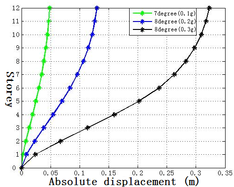
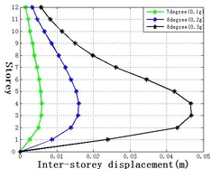
The inter-storey displacement and the absolute displacement of each storey under 7 degree (0.1g), 8 degree (0.2g) and 8 degree (0.3g) earthquakes are shown in Figure 12.
| Inter-storey displacement | 7degree (0.1g) | 8degree (0.2g) | 8degree (0.3g) |
| Storey 1 (m) | 0.0026 | 0.0087 | 0.0239 |
| Storey 2 (m) | 0.005 | 0.0139 | 0.0429 |
| Storey 3 (m) | 0.0058 | 0.0158 | 0.0467 |
| Storey 4 (m) | 0.0059 | 0.016 | 0.0466 |
| Storey 5 (m) | 0.0056 | 0.0153 | 0.0421 |
| Storey 6 (m) | 0.0052 | 0.0139 | 0.0345 |
| Storey 7 (m) | 0.0046 | 0.0123 | 0.0262 |
| Storey 8 (m) | 0.0039 | 0.0105 | 0.0198 |
| Storey 9 (m) | 0.0034 | 0.0086 | 0.015 |
| Storey 10 (m) | 0.0027 | 0.0066 | 0.0114 |
| Storey 11 (m) | 0.0022 | 0.0047 | 0.0082 |
| Storey 12 (m) | 0.0015 | 0.0033 | 0.0057 |
| Top displacement (m) | 0.0484 | 0.1296 | 0.323 |
| Maximum inter-storey displacement (m) | 0.0059 | 0.0094 | 0.0467 |
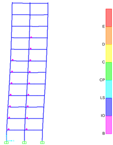
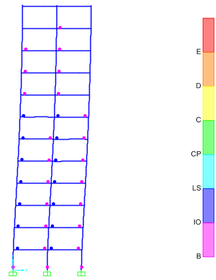
Take the two sheets (the sheet 2 and 3, see Figure 10) that deformed significantly under earthquakes of various intensity for analysis, and the plastic hinge distributions are shown in Figure 13.
It can be seen from Figure 13 that under the action of an earthquake of 7 degrees (0.1g), pink plastic hinges appear on the first to ninth storey beams of sheet 2. Under the action of an earthquake of 8 degrees (0.2g), dark blue hinges appear on the first to seventh storey beams of sheet 3, and pink hinges start to appear on the first storey columns. Under the action of 8 degree (0.3g) earthquake, red plastic hinges appear on the second to fourth storey beams of sheet 2, and plastic hinges of varying degrees appear on the first to ninth storey columns.
5. Conclusion
1. The 12-storey special-shaped column structure with a height of 34.8m is basically intact under the action of a 7 degree (0.1g) earthquake. It is slightly damaged under the action of an 8 degree (0.2g) earthquake. Under the action of an 8 degree 0.3g earthquake, it collapses.
2. For a regular concrete frame with special-shaped columns, the weak layer may appear in the lower part of the structure, and the damage belongs to the beam hinge mechanism.
3. The side columns and central columns in the regular special-shaped column frame are damaged earlier than corner columns.
References
[1] Technical specification for concrete structures with specially shaped columns (JGJ149-2017). China Architecture & Building Press, Beijing, 2017.
[2] Shen P. Design and construction of special-shaped column structure. China Machine Press, Beijing, 2010.
[3] Tian W., Zhou M., Chen S. Design of concrete special-shaped column structure. China Architecture & Building Press, Beijing, 2007.
[4] Shi G., Atluri S. N. Elasto-plastic large deformation analysis of space-frames: A plastic-hinge and stress-based explicit derivation of tangent stiffnesses. International Journal for Numerical Methods in Engineering, 26: 589-615, 1988.
[5] Richard Liew J.Y., Chen H., Shanmugam N.E. Improved nonlinear plastic hinge analysis of space frame structures. Engineering Structures, 22: 1324-1338, 2000.
[6] CSI Analysis Reference Manual for SAP2000, ETABS, and SAFE. Computer and Structures, Inc, Berkeley, 2007.
[7] Scott M.H., Fenves G.L. Plastic Hinge Integration Methods for Force-Based Beam-Column Elements. Journal of Structural Engineering, 132: 244-252, 2006.
[8] FEMA 356. Prestandard and commentary for the Seismic Rehabilitation of Buildings. Federal Emergency Management Agency, 2000.
[9] Code for design of concrete structure (GB50010-2010). China Architecture & Building Press, Beijing, 2011.
[10] Krawinkler H., Seneviratna G.D.P.K. Pros and cons of a pushover analysis of seismic performance evaluation[J]. Engineering Structures, 20(4-6):452-464, 1998.
[11] Einashai A.S. Advanced inelastic static (pushover) analysis for earthquake applications. Structural Engineering & Mechanics, 12(1):51-69, 2001.
[12] Hou S.,Ou J. A study of load pattern selection of pushover analysis and influence of higher modes. Earthquake Engineering & Engineering Vibration, 24(3): 89-97, 2004.
[13] Zou X.K., Chan C.M. Optimal seismic performance-based design of reinforced concrete buildings using nonlinear pushover analysis. Engineering Structures, 27: 1289 - 1302, 2005.
[14] ATC-40. Seismic Evaluation and Retrofit of Concrete Buildings: Volume 1. Report No. SSC 96-01. Applied Technology Council, Redwood City, California, 1996.
[15] Code for seismic design of buildings (GB50011-2010). China Architecture & Building Press, Beijing, 2016.
[16] Beijing civil king software technology Co., Ltd. SAP2000 User Guide. China Communications Press, Beijing, 2012.
Document information
Published on 14/04/21
Accepted on 06/04/21
Submitted on 05/09/20
Volume 37, Issue 2, 2021
DOI: 10.23967/j.rimni.2021.04.004
Licence: CC BY-NC-SA license
Share this document
claim authorship
Are you one of the authors of this document?
