| Line 707: | Line 707: | ||
{| class="floating_imageSCP" style="text-align: center; border: 1px solid #BBB; margin: 1em auto; width: 100%;max-width: 100%;" | {| class="floating_imageSCP" style="text-align: center; border: 1px solid #BBB; margin: 1em auto; width: 100%;max-width: 100%;" | ||
|- | |- | ||
| − | |[[Image:Draft_Samper_933320449-tubo3.png| | + | |[[Image:Draft_Samper_933320449-tubo3.png|500px|Inflation of a tubular arch. (a) Deflated tube. (b),(c) Deformed configuration during the inflation process. (d) Final inflated configuration]] |
|- style="text-align: center; font-size: 75%;" | |- style="text-align: center; font-size: 75%;" | ||
| colspan="1" | '''Figure 11:''' Inflation of a tubular arch. (a) Deflated tube. (b),(c) Deformed configuration during the inflation process. (d) Final inflated configuration | | colspan="1" | '''Figure 11:''' Inflation of a tubular arch. (a) Deflated tube. (b),(c) Deformed configuration during the inflation process. (d) Final inflated configuration | ||
Revision as of 12:41, 2 May 2019
Published in Recent Advances in Textile Membranes and Inflatable Structures Springer Verlag, pp. 69 - 88, 2005
DOI: 10.1007/1-4020-3317-6_5
Abstract
This paper shows applications of a recently developed shell element to the analysis of thin shell and membrane structures. The element is a three node triangle with only translational DOFs (rotation free) that uses the configuration of the three adjacent elements to evaluate the strains. This allows to compute (constant) bending strains and (linear) membrane strains. A total Lagrangian formulation is used. Strains are defined in terms of the principal stretches. This allows to consider rubber materials and other type of materials using the Hencky stress-strain pair. An explicit central difference scheme is used to integrate the momentum equations. Several examples, including inflation and deflation of membranes show the excellent convergence properties and robustness of the element for large strain analysis of thin shells and membranes.
Keywords airbag inflation, deflation, shell triangular elements, rotation free, membranes
1 Introduction
The simulation of the inflation of membrane structures is normally performed with membrane finite elements, i.e. no bending stiffness included. The formulation of such elements is simple as they only require continuity [1], in contrast with elements based on thin shell theory where continuity implies important obstacles [2] in the development of conforming elements. Triangular elements are naturally preferred as they can easily adapt to arbitrary geometries and due to the robustness of the associated mesh generators.
When only the final configuration of the membrane is of interest implicit programs are normally used, including special algorithms due to the lack of stiffness of the membrane when no tensile stresses are yet present. When the inflation/deflation process is of interest, the use of programs with explicit integration of the momentum equations are largely preferred. In the latter case linear strain triangles are normally not effective, specially when contact between surfaces is present. This implies a fine discretization of constant strain triangles to capture the details, what makes simulation quite expensive due to the time increment limitations. In this paper a triangular finite element with similar convergence properties to the linear strain triangle, but without its drawbacks, is used.
Membrane structures components have some, although small, bending stiffness that in most of the cases is sensibly disregarded. However in many cases it may be convenient to include bending energy in the models due to the important regularization effect it supposes. Shell elements are of course more expensive due the increase in degrees of freedom (rotations) and integration points (through the thickness). In the last few years shell elements without rotation degrees of freedom have been developed (see [3]–[10] among others), which make shell elements more efficient for both implicit and explicit integrators.
The outline of this papers is as follows. Next section summarizes the rotation-free shell triangle used [10]. Sec. 3 shows convergence properties of the element in 2-d plane stress problems and 3-d linear bending/membrane problems. Sec. 4 presents examples of inflation/deflation of membranes with and without bending stiffness. Finally Sec. 5 summarizes some conclusions.
2 Formulation of the Rotation Free Shell Triangle
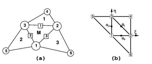
The rotation-free EBST (for Enhanced Basic Shell Triangle) element has three nodes with three displacement degrees of freedom at each node. An element patch is defined by the central triangle and the three adjacent elements (Fig. 1). This patch helps to define the membrane strains and curvature field within the central triangle (the EBST element) in terms of the displacement of the six patch nodes.
The node-ordering in the patch is the following (see Fig. 1.a)
|
| Figure 1: Patch of elements for strain computation. (a)in spatial coordinates (b)in natural coordinates |
- The nodes in the main element (M) are numbered locally as 1, 2 and 3. They are defined counter-clockwise around the positive normal
- The sides in the main element are numbered locally as 1, 2, and 3. They are defined by the local node opposite to the side
- The adjacent elements (which are part of the cell) are numbered with the number associated to the common side
- The extra nodes of the cell are numbered locally as 4, 5 and 6, corresponding to nodes on adjacent elements opposite to sides 1, 2 and 3 respectively
- The connectivities in the adjacent elements are defined beginning with the extra node.
Any convenient in plane local cartesian coordinate system can be defined for the patch, with the unit normal to the plane.The main features of the element formulation are the following:
- The geometry of the patch formed by the central element and the three adjacent elements is quadratically interpolated from the position of the six nodes in the patch
- The membrane strains are assumed to vary linearly within the central triangle and are expressed in terms of the (continuous) values of the deformation gradient at the mid side points of the triangle
- An assumed constant curvature field within the central triangle is obtained using the values of the (continuous) deformation gradient at the mid side points.
Details of the derivation of the EBST element are given below.
2.1 Definition of the Element Geometry and Computation of Membrane Strains
As mentioned above a quadratic approximation of the geometry of the patch of four elements is chosen using the position of the six nodes. It is useful to define the patch in the isoparametric space using the nodal positions given in the Table 1 (see also Fig. 1.b).
| 1 | 2 | 3 | 4 | 5 | 6 | |
| 0 | 1 | 0 | 1 | -1 | 1 | |
| 0 | 0 | 1 | 1 | 1 | -1 |
The quadratic interpolation for the geometry is defined by
|
|
(1) |
with being the position vector of node , and
|
|
(2) |
this interpolation allows to compute the displacement gradients at selected points in order to use an assumed strain approach. The computation of the gradients is performed at the mid side points of the central element (M) denoted by , and in Fig. 1.b. This choice has the advantage that gradients at the three mid side points depend only on the nodes belonging to the two elements adjacent to each side. When gradients are computed at the common mid-side point of two adjacent elements, the same values are obtained, as the coordinates of the same four points are used. This in practice means that the gradients at the mid-side points are independent of the element where they are computed.
The deformation gradient at the mid-side points of the element are obtained from the quadratic interpolations (1) as
|
|
(3) |
In Eq.(3) denotes values computed at the ith mid-side point.
The cartesian derivatives of the shape functions are computed at the original configuration by the standard expression
|
|
(4) |
where the Jacobian matrix at the original configuration is
|
|
(5) |
Once the deformation gradient is obtained, any convenient strain measure can be coupled. The membrane strains within the central triangle are now obtained using a linear assumed membrane strain field , i.e.
|
|
(6) |
with
|
|
(7) |
where are the membrane strains computed at the three mid side points ( see Fig. 2). In (7)
|
|
(8) |
If, for example, Green-Lagrange strains are used,
|
|
(9) |
substituting (3) into (9) and using the usual membrane strain vector [11]
|
|
(10) |
equation (7) gives
|
|
(11) |
The virtual membrane strains are expressed by
|
|
(12) |
2.2 Computation of Curvatures
The curvatures (second fundamental form) of the middle surface are defined by []
|
|
(13) |
We will assume the following constant curvature field within each element
|
|
(14) |
where is the assumed constant curvature field obtained as
|
|
(15) |
and is the area (in the original configuration) of the central element in the patch.
Substituting (15) into (14) and integrating by parts the area integral gives the curvature vector [11] within the element in terms of the following closed line integral
|
|
(16) |
where are the components (in the local system) of the normals to the element sides in the initial configuration .
For the definition of the normal vector , the linear interpolation of the position vector over the central element is used.
|
|
(17) |
where are the standard linear shape functions of the central triangle (area coordinates) [11]. In this case the tangent plane components are
|
|
(18) |
|
|
(19) |
From these expressions it is also possible to compute in the original configuration the element area , the outer normals at each side and the side lengths . Equation (19) also allows to evaluate the thickness ratio in the deformed configuration and the actual normal .
Direction t can be seen as a reference direction. If a different direction than that given by (19) is chosen, at an angle with the former, this has an influence of order in the computation of the curvatures (see (23) below). This justifies (19) for the definition of t as a function exclusively of the three nodes of the central triangle, instead of using the 6-node isoparametric interpolation.
The numerical evaluation of the line integral in (16) results in a sum over the integration points at the element boundary which are, in fact, the same points used for evaluating the gradients when computing the membrane strains. As one integration point is used over each side, it is not necessary to distinguish between sides () and integration points ().
The explicit form of the gradient evaluated at each side (3) from the quadratic interpolation is
|
|
(20) |
We note again that the gradient at each mid side point depends only on the coordinates of the three nodes of the central triangle and on those of an additional node in the patch, associated to the side where the gradient is computed.
In this way the curvatures can be computed by
|
|
(21) |
An alternative form to express the curvatures, which is useful when their variations are needed, is to define the vectors
|
|
(22) |
This gives
|
|
(23) |
The variation of the curvatures can be obtained as
|
|
(24) |
where the projections of the vectors over the contravariant base vectors have been included
|
|
(25) |
with
|
In above expressions superindexes in and refer to element numbers whereas subscripts denote node numbers. As before the superindex denotes values in the central triangle (Fig. 1.a). Note that as expected the curvatures (and their variations) in the central element are a function of the nodal displacements of the six nodes in the four elements patch.
Details of the derivation of (12) and (24) can be found in [10]. The explicit expressions of the membrane and curvature matrices can be found in [12]. The derivation of the element stiffnes matrix is described in [10, 12]. Also in [10, 12] details of the quasi-static formulation and the fully explicit dynamic formulation are given.
It must be noted that while the membrane strains are linear the curvature strains are constant. A full numerical integration of the stiffness matrix terms requires three points for the membrane part and one point for the bending part. Numerical experiments show that:
- when using one or three integration points the element is free of spurious energy modes and passes the patch test
- for initial curved surfaces the element with full (three point) integration leads to some membrane locking. This defect dissapears if one integration point is used for the membrane stiffness term.
It can also be observed that:
- for large strain elastic or elastic-plastic problems membrane and bending parts can not be integrated separately, and a numerical integration trought the thickness must be performed
- for explicit integrators (hydro codes) is much more effective to use only one integration point for both the membrane and bending parts.
Above arguments lead to reccomended the use of one integration point for both membrane and bending parts. This element is termed EBST1 to distinguish from the fully integrated one.
2.3 Boundary Conditions
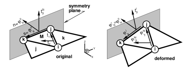
Elements at the domain boundary, where an adjacent element does not exist, deserve a special attention. The treatment of essential boundary conditions associated to translational constraints is straightforward, as they are the degrees of freedom of the element. The conditions associated to the normal vector are crucial in this formulation for bending. For clamped sides or symmetry planes, the normal vector must be kept fixed (clamped case), or constrained to move in the plane of symmetry (symmetry case). The former case can be seen as a special case of the latter, so we will consider symmetry planes only. This restriction can be imposed through the definition of the tangent plane at the boundary, including the normal to the plane of symmetry that does not change during the process.
|
| Figure 2: Local cartesian system for the treatment of symmetry boundary conditions |
The tangent plane at the boundary (mid-side point) is expressed in terms of two orthogonal unit vectors referred to a local-to-the-boundary Cartesian system (see Fig. 2) defined as
|
|
(28) |
where vector is fixed during the process while direction emerges from the intersection of the symmetry plane with the plane defined by the central element (). The plane (gradient) defined by the central element in the selected original convective Cartesian system () is
|
|
(29) |
the intersection line (side ) of this plane with the plane of symmetry can be written in terms of the position of the nodes that define the side ( and ) and the original length of the side , i.e.
|
|
(30) |
That together with the outer normal to the side (resolved in the selected original convective Cartesian system) leads to
|
|
(31) |
where, noting that is the determinant of the gradient, the normal component of the gradient can be approximated by
|
|
(32) |
In this way the contribution of the gradient at side to vectors (22) results in
|
|
(33) |
For a simple supported (hinged) side, the problem is not completely defined. The simplest choice is to neglect the contribution to the side rotations from the adjacent element missing in the patch in the evaluation of the curvatures via (16) [6, 8]. This is equivalent to assume that the gradient at the side is equal to the gradient in the central element. More precise changes can be however introduced to account for the different natural boundary conditions. One may assume that the curvature normal to the side is zero, and consider a contribution of the missing side to introduce this constraint. As the change of curvature parallel to the side is zero along the hinged side, both things lead to zero curvatures in both directions. For the case of a triangle with two sides associated to hinged sides, the normal curvatures to both sides must be set to zero.
For a free edge the same approximation can be used but due to Poisson's effect this will lead to some error.
For the membrane formulation of the EBST element, the gradient at the mid-side point of the boundary is assumed to be equal to the gradient of the main triangle.
2.4 Constitutive Models
In the numerical experiments presented below two constitutive models have been used. A standard linear elastic orthotropic material and a hyper-elastic material for rubbers.
For the case of rubbers, the Ogden [13] model extended to the compressible range is considered. The material behaviour is characterized by the strain energy density per unit undeformed volume defined as
|
|
(34) |
where is the bulk modulus of the material, are the principal strain ratios, is the determinant of the deformation gradient (), , and are material parameters, are real numbers such that and is a positive integer.
3 Convergence Studies
In this section three examples are presented to show the convergence properties and the performance of present element. Examples are solved with a implicit program capable of dealing static/dynamic problems with moderate non-linearities.
3.1 Cook's Membrane Problem
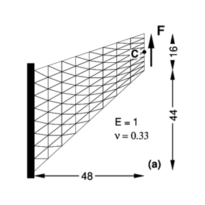
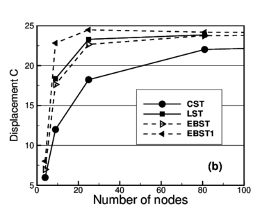
One of the main targets of the rotation-free triangular element is to obtain a membrane element with a behaviour similar to the linear strain triangle (LST). Such capacity is studied in this example [14] corresponding to a problem with an important amount of shear energy involved. This problem is also intended also to assess the ability of the element to distort. Figure 3.a shows the geometry of a tapered panel clamped on one side and with a uniformly distributed shear load in the opposite side. Figure 3.b presents the vertical displacement of point (mid point of the loaded side) for the uniformly refined meshes considered as a function of the total number of nodes in the mesh.
|
|
| Figure 3: Cook's membrane problem. (a) Geometry and load (b) Vertical displacement of point C for different meshes | |
For the EBST element with three integration points, it can be seen that for the coarsest mesh (two linear elements), the measured displacement is slightly superior than the constant strain triangle (CST); but when the mesh is refined, values rapidly catch up with those obtained with the linear strain triangle. The element with only one integration point (EBST1) shows excellent predictions for coarse meshes and fast convergence properties for the reported displacement.
3.2 Cylindrical Roof
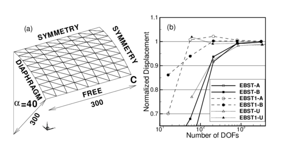
In this example an effective membrane interpolation is of primary importance. Hence this is good test to assess the rotation-free element. The geometry is a cylindrical roof supported by a rigid diaphragm at both ends and it is loaded by a uniform dead weight (see Fig. 4.a). Only one quarter of the structure is meshed due to symmetry conditions. Unstructured and structured meshes are considered. In the latter case two orientations are possible (Fig. 4.a shows orientation B).
|
| Figure 4: Cylindrical roof under dead weight. , , Thickness =3.0, shell weight =0.625 per unit area. (a)Geometry. (b)Normalized displacement of point “C” for different meshes |
Figure 4.b shows the normalized vertical displacement of the midpoint of the free side (point-C) over both ( and ) structured and () unstructured meshes as a function of the number of free degrees of freedom. Value used for normalization is as quoted in [15].
An excellent convergence of the EBST element can be seen. The version with only one integration point (EBST1) presents a behaviour a little more flexible and converges from above. For non-structured meshes the result converges to the reference value but a bit more slowly.
3.3 Inflation of a Sphere
As the EBST element uses a quadratic interpolation of geometry, the existance of membrane locking must be assessed. For this example an originally curved surface is considered, where a standard linear strain triangle would lead to membrane locking. The example is the inflation of a spherical shell under internal pressure. An incompressible Mooney-Rivlin constitutive material have been considered. The Ogden parameters are , , , , . Due to the simple geometry an analytical solution exists [16] (with ):
|
|
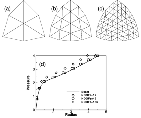
In this numerical simulation the same geometric and material parameters used in [9] have been adopted: and . The three meshes considered to evaluate convergence are shown in Fig. 5.a-c. The EBST1 element has been used. The value of the actual radius as a function of the internal pressure is plotted in Fig. 5.d for the different meshes and is also compared with the analytical solution. It can be seen that with a few degrees of freedom it is possible to obtain an excellent agreement for the range of strains considered. The final value corresponds to a thickness radius ratio of . No membrane locking has therefore been detected in this problem.
|
| Figure 5: Inflation of sphere of Mooney-Rivlin material. (a)-(c) EBST1 meshes used in the analysis (d)Radius as a function of the internal pressure |
4 Thin Shells and Membranes
Results for examples with geometric and material non-linearities are presented next using the EBST1 element [10]. Due to the features of the modelled problems, with strong non linearities associated to instabilities and contact, a code with explicit integration of the dynamic equilibrium equations has been used [17]. This code allows to obtain pseudo-static solutions through dynamic relaxation. In most of the examples contact situations appear, including contact with walls, objects or self contact due to folds and wrinkles. A standard penalty formulation is used for contact assumed frictionless in the cases.
4.1 Inflation/Deflation of a Circular Airbag
This example has been taken from [9] where it is shown that the final configuration is mesh dependent due to the strong instabilities leading to a non-uniqueness of the solution. In [9] it is also discussed the important regularizing properties of the bending energy, that when disregarded leads to massive wrinkling in the compressed zones.
|
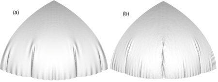
| Figure 6: Inflation of a circular airbag. Deformed configurations for final pressure. (a) bending effects included (b) membrane solution only |
The airbag geometry is initially circular with an undeformed radius of . The constitutive material is a linear isotropic elastic one with modulus of elasticity and Poisson's ratio . Arbitrarily only one quarter of the geometry has been modelled. Only the normal displacement to the original plane is constrained along the boundaries. The thickness considered is and the inflation pressure is . Using a density , pressure is linearly increased from 0 to the final value in .
With comparative purposes and also to backup the comments in Ref. [9] two analyses have been performed, a purely membrane one and one including bending effects. Figure 6 shows the final deformed configurations for a mesh with 10201 nodes and 20000 elements. The figure on the left (a) corresponds to a full analysis including bending and the right figure (b) is a pure membrane analysis.
We note that when the bending energy is included a more regular final pattern is obtained. Also the final pattern is rather independent of the discretization (note that the solution is non unique due to the strong instabilities). On the other hand, the pure membrane solution shows a a noteworthy increment of “numerical” wrinkles.
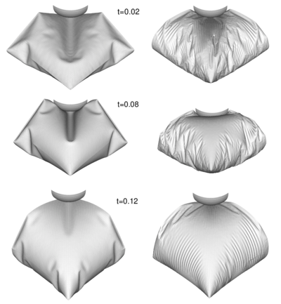
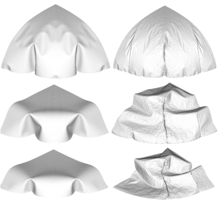
Figure 7 shows the results obtained for the de-inflation process for three different times. Column on the left corresponds to the analysis with bending energy included. Note that the spherical membrane falls down due to the self weight. The final configuration is of course non-unique.
|
| Figure 7: Deflation of a circular air-bag. Left figure: results obtained with the full bending formulation. Right figure: results obtained with a pure membrane solution |
4.2 Inflation of a Square Air-bag
This example has also been taken from [9]. Again the final configuration is mesh dependent due to the strong instabilities leading to a non-uniqueness of the solution.
The air bag geometry is initially square with an undeformed diagonal of . The constitutive material is a linear isotropic elastic one with modulus of elasticity and Poisson's ratio . Only one quarter of the geometry has been modelled due to symmetry. Only the normal to the original plane is constrained along the boundaries. The thickness considered is and the inflation pressure is . Using a density , pressure is linearly increased from 0 to the final value in .
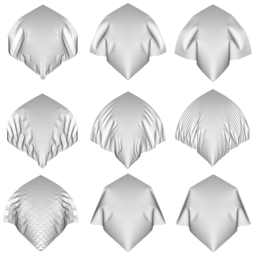
Two analyses have been performed, a purely membrane one and another one including bending effects. Figure 8 shows the final deformed configurations for three meshes with 289, 1089 and 4225 nodes. The top row corresponds to a full analysis including bending and the central row is a pure membrane analysis. The bottom row is also an analysis including bending where the mesh orientation has been changed.
The top and bottom lines show the final shapes change according to the degree of discretization and mesh orientation due to instabilities and non uniqueness of the solution. The central row shows the pure membrane solution with a wrinkling pattern where the width of the wrinkle is the length of the element.
|
| Figure 8: Inflation of a square air-bag. Deformed configurations for three different meshes with 800, 3136 and 12416 degrees of freedom |
4.3 Inflation of a Square Airbag Against a Spherical Object
The last example of this kind is the inflation of a square airbag supporting a spherical object. This example resembles a problem studied (numerically and experimentally) in [18], where fluid-structure interaction is the main subject. Here fluid is not modelled, and a uniform pressure is applied over all the internal surfaces. The lower surface part of the airbag is limited by a rigid plane and on the upper part a spherical dummy object is set to study the interaction between the airbag and the object.
The airbag geometry is initially square with an undeformed side length of . The constitutive material used is a linear isotropic elastic one with modulus of elasticity and Poisson's ratio . Only one quarter of the geometry has been modelled due to symmetry. The thickness considered is and the inflation pressure is . Using a density , pressure is linearly increased from 0 to the final value in . The spherical object has a radius and a mass of (one quarter), and is subjected to gravity load during all the process.
The mesh includes 8192 EBST1 elements and 4225 nodes on each surface of the airbag. Figure 9 shows the deformed configurations for three different times. The sequence on the left of the figure corresponds to an analysis including full bending effects and the sequence on the right is the result of a pure membrane analysis.
4.4 Inflation/Deflation of a Closed Tube
|
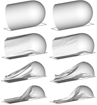
| Figure 10: Inflation and deflation of a closed tube. , , . Left figure: results obtained with the full bending formulation. Right figure: results obtained with a pure membrane solution |
The last problem is the study of the inflating and de-inflating of a tube with a semi-spherical end cap. The tube diameter is , its total length is and the thickness . The material has the following properties , , . The tube is inflated fast until a pressure of and when pressure is released the tube de-inflates and falls under self weight. The analysis is performed with a mesh of 16704 EBST1 elements and 8501 nodes modelling a quarter of the geometry. A rigid frictionless base is supposed below. Self contact is also included to avoid penetrations. The evolution of the tube walls during the de-inflating process can be seen in Fig. 10. Note that the central part collapses as expected, while a great part of the semi-spherical cap remains unaltered. For this very thin shell, the differences between a full bending solution and a pure membrane solution are less marked. It must be noted that present element does not presents problems in the very thin limit as the formulation is based on classical thin shell theory and the rotational variables have been elliminates. So the time increment is independent of the thickness.
4.5 Inflation of a Tubular Arch
The last example is the analysis of a tubular arch. This kind of archs are joined together to form large inflatable structures to be used for different purposes. The analized tubular arch has a internal diameter of ; is total length is and the heigth is . The tube thickness is , the constitutive material is polyamid with Young modulus and Poisson ratio . Due to geometric symmetrys one quarter of the tube was discretized with 33600 triangular elements (17061 nodes). The simulation includes two stages. First the tube is left fall down under gravity action. Second an internal pressure of is applied in a short time and kept constant afterwards until the full inflation of the tube is reached.
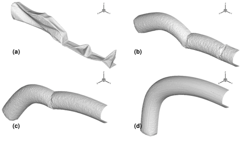
Figure 11 shows deformed configurations for different instants of the process.
|
| Figure 11: Inflation of a tubular arch. (a) Deflated tube. (b),(c) Deformed configuration during the inflation process. (d) Final inflated configuration |
5 Concluding Remarks
We have presented in the paper the formulation of a rotation-free enhanced basic shell triangle (EBST) using an assumed strain approach. The element is based on an assumed constant curvature field expressed in terms of the nodal deflections of a patch of four elements and an assumed linear membrane strain field for the in-plane behaviour. A simple and economic version of the element using a single integration point has been presented. The EBST1 element has proven to be an excellent candidate for solving practical engineering shell and membrane problems involving complex geometry, dynamics, material non linearity and frictional contact conditions. In the simulation of membranes, bending have been included to avoid massive wrinkling in the compressed zones. The inclusion of bending energy (two integration points through the thickness instead of one) represents an increase of 40% of CPU time.
Acknowledgments
The first author is a member of the scientific staff of the Science Research Council of Argentina (CONICET). The support provided by grants of CONICET and Agencia Córdoba Ciencia S.E. and the support of the company QUANTECH (http://www.quantech.es/) providing the code STAMPACK are gratefully acknowledged.
References
[1] Taylor RL (2001) Finite element analysis of membrane structures. Publication 203, CIMNE, Barcelona
[2] Oñate E (1994) A review of some finite element families for thick and thin plate and shell analysis. Publication 53, CIMNE, Barcelona
[3] Hampshire JK, Topping BHV, Chan HC (1992) Three node triangular elements with one degree of freedom per node. Engng Comput 9:49–62
[4] Phaal R, Calladine CR (1992) A simple class of finite elements for plate and shell problems. II: An element for thin shells with only translational degrees of freedom. Num Meth Engng 35:979–996
[5] Oñate E, Cervera M. (1993) Derivation of thin plate bending elements with one degree of freedom per node. Engineering Computations 10:553–561
[6] Oñate E, Zárate F (2000) Rotation-free plate and shell triangles. Num Meth Engng 47:557–603
[7] Cirak F, Ortiz M (2000) Subdivision surfaces: A new paradigm for thin-shell finite element analysis. Num Meths Engng 47:2039–2072
[8] Flores FG, Oñate E (2001) A basic thin shell triangle with only translational DOFs for large strain plasticity. Num Meths Engng 51:57–83
[9] Cirak F, Ortiz M (2001) Fully -conforming subdivision elements for finite deformations thin-shell analysis. Num Meths Engng 51:813–833
[10] Flores FG, Oñate E. (2003) Improvements in the membrane behaviour of the three node rotation-free BST shell triangle using an assumed strain approach. Comput Meth Appl Mech Engng (in press)
[11] Zienkiewicz OC, Taylor RL (2000) The finite element method. Vol II: Solid Mechanics, Butterworth-Heinemann, place?
[12] Oñate E, Flores FG (2004) Advances in the formulation of the rotation-free basic shell. Comput Meth Appl Mech Engng (in press)
[13] Ogden RW (1972) Large deformation isotropic elasticity: on the correlation of theory and experiments for incompressible rubberlike solids. Proc Royal Society London A326:565–584
[14] Cook RD (1974) Improved two-dimensional finite element, ASCE J Struct Div 100(ST6):1851–1863
[15] Huang HC (1989) Static and Dynamic Analysis of Plates and Shells. Springer-Verlag, Berlin
[16] Needleman A (1977) Inflation of spherical rubber ballons. Solids and Structures 13:409–421
[17] STAMPACK (2003) A General Finite Element System for Sheet Stamping and Forming Problems, Quantech ATZ, Barcelona
[18] Marklund PO. Nilsson L (2002) Simulation of airbag inflation processes using a coupled fluid structure approach. Computational Mechanics 29:289–297
Document information
Published on 01/01/2005
DOI: 10.1007/1-4020-3317-6_5
Licence: CC BY-NC-SA license
Share this document
Keywords
claim authorship
Are you one of the authors of this document?
