m (Jorge moved page Draft Hernández-Gómez 388037288 to Review Torres-San-Miguel et al 2017a) |
|||
| Line 13: | Line 13: | ||
|<math>^2</math> Centro de Desarrollo Aeroespacial, Instituto Politécnico Nacional | |<math>^2</math> Centro de Desarrollo Aeroespacial, Instituto Politécnico Nacional | ||
|- | |- | ||
| − | | Belisario | + | | Belisario Domínguez 22, Centro, Ciudad de México, 06610, México. |
|- | |- | ||
| | | | ||
| Line 33: | Line 33: | ||
==Abstract== | ==Abstract== | ||
| − | In this work, design, manufacture and surgical success of a personalised temporomandibular prosthesis is featured. A fused deposition modelling technique and Die forging process constitute the methodology used in a patient who had an amputation in the upper third branch of the mandible, without considering the joint capsule. The implant was designed using a processed resection image of a computational tomography and using the methodology of | + | In this work, design, manufacture and surgical success of a personalised temporomandibular prosthesis is featured. A fused deposition modelling technique and Die forging process constitute the methodology used in a patient who had an amputation in the upper third branch of the mandible, without considering the joint capsule. The implant was designed using a processed resection image of a computational tomography and using the methodology of zkaya and Nordin. The jaw operating conditions were simulated by the finite element method (FEM). The main considered factors were the morphological geometry of the patient, implant fixation in the first third of the branch, implant fixation on the chin, dental post for placement of the teeth, and the form of the sub-lingual fossa weight optimisation. Special consideration was to preserve the patients facial aesthetics. |
'''Keywords:''' CAD|CAM; Custom prosthesis; FDM; FEM; Digital temporomandibular models; | '''Keywords:''' CAD|CAM; Custom prosthesis; FDM; FEM; Digital temporomandibular models; | ||
| Line 39: | Line 39: | ||
==2 Introduction== | ==2 Introduction== | ||
| − | + | Consequences of deceases are diverse, and might lead to total or partial loss of a member by amputation, that can significantly affect the patient. The replacement of an organ or a member with prosthesis can represent, for the person, a recovery of an aptitude to perform different tasks and even organic basic functions. According to <span id='citeF-1'></span>[[#cite-1|[1]]], psycho-social aspects toughen the patient in the recovery phase from surgery, mainly do to the number of successful - or not - surgical procedures. Such psycho-social deterioration is sometimes more incapacitating than the perception of the efficiency of undertaken surgical approach. Besides psycho-social, aesthetic aspects also affect the patient. All these factors contribute to his quality of life. | |
| − | + | In the case of low jaw, important factors to be considered to select the best method to reconstruct it could be the patient psychological aspects, the affecting disease, the expected quality of life, the age, height and weight of the jaw bone, the state of teeth, etc. It is also important to grant aesthetic aspects to the face in order to reinforce the natural person's confidence. Nevertheless, even with technological advances, complications in chewing, deficient sensing, infections, and weakness in the strength of the face structure are prone to exist. | |
| − | <span id='citeF-5'></span>[[#cite-5|[5]]], | + | Much research has been done in the field of low jaw reconstruction. From open academic literature, the biomedical comparison between fixing a Titanium plate to the lateral edge of the jaw as well as to the low jaw edge is reported by <span id='citeF-2'></span>[[#cite-2|[2]]], finding significant differences in the implant's mechanical behaviour. In <span id='citeF-3'></span>[[#cite-3|[3]]], authors manufacture a replacement with specific measures of the patient's jaw, obtained prior to surgical procedure, yielding to a prosthesis which is very close to the original bone configuration of the patient. A 3D study, from tomographic resources, was developed by <span id='citeF-4'></span>[[#cite-4|[4]]], which allowed to determine the existence of mineralisation of the cortical bone distribution part. Additionally, in <span id='citeF-5'></span>[[#cite-5|[5]]], authors applied a 3D model to known the mechanical behaviour of the jaw, determining that it bears a load up to 107N/m<math display="inline">^2</math>. This loading condition is generated by impact, and could lead to fractures at low jaw <span id='citeF-5'></span>[[#cite-5|[5]]]. An anosteosynthesis plate for an atrophic jaw, by using a mono cortical osteosynthesis of 2 Titanium plates was developed by <span id='citeF-6'></span>[[#cite-6|[6]]]. On the other side, it has been shown that a subjection element at the plate produces a better behaviour at the connection implant when chewing than other positions of implant subjection elements for grafts implants <span id='citeF-7'></span>[[#cite-7|[7]]]. Also, in <span id='citeF-8'></span>[[#cite-8|[8]]], authors performed a jaw reconstruction by means of free human tissue transfer, concluding that the main parts are iliac and scapula, which allow the mobility of the tongue, so they have to be considered in jaw reconstruction. Authors of <span id='citeF-9'></span>[[#cite-9|[9]]] analysed jaw reconstruction using 3D models of calcium in order to manufacture a physical model of jaw prosthesis, by considering that performing a pre-operational analysis, should allow more accurate reconstruction plates improving implant alignment. |
| − | <span id='citeF-10'></span>[[#cite-10|[10]]] | + | In the side of applying numerical tools of engineering to the problem, also much research has been done. In <span id='citeF-10'></span>[[#cite-10|[10]]], authors developed a study to determine the human jaw elastic response, by using finite element algorithms derived from mechanical loads. In the same mood, lateral movement of jaw, as well as collateral ligaments that connect articulate discs to condyle poles was simulated by Finite Element Method (FEM) <span id='citeF-11'></span>[[#cite-11|[11]]]. The later study determined that the function of temporomandibular ligament is to guide jaw during its motion. In other study, vascular micro-grafts were used to reconstruct an atrophied due to a tumour extraction, concluding that bone grafts immediately inserted after resection could be better treated for these types of tumours <span id='citeF-12'></span>[[#cite-12|[12]]]. In <span id='citeF-13'></span>[[#cite-13|[13]]], authors performed a complete jaw numerical analysis by FEM; the model construction was estimated by contour conditions, the loading settings and the jaw limit displacement circumstances. Finally, authors of <span id='citeF-14'></span>[[#cite-14|[14]]] developed the numerical analysis of a 3D biomechanical model of the oral cavity to predict consequences of tongue surgery on tongue movements, according to the size and location of the lost tissue, as well as the nature of the flap used by the surgeon. |
| − | + | In the field of patents, a wide range of geometries and morphologies of implants that aid in the treatment of diverse pathologies, have been reported. A modular type of mandibular prosthesis used for jaw resection, which considers the replacement of the jaw bone, by analysing the total jaw angle was proposed by <span id='citeF-15'></span>[[#cite-15|[15]]]. The later prosthesis was developed by a sub-application of a couple of plates and a set of links used as connector elements. In <span id='citeF-16'></span>[[#cite-16|[16]]], authors proposes a bio-compatible prosthetic device for the replacement of temporomandibular joint, which contemplates the substitution of the condyle neck, the condyle, as well as condyle pit; this device includes a convex spherical surface condyle component of the first radio for the substitution of the articulate surface of the condyle head. A new fixation method, that allows a free rotation of the elements in a portion at the edge that surrounds the fixation protuberance, over a bolted extreme neck that extends from the fixed plate to the mandibular, was developed by <span id='citeF-17'></span>[[#cite-17|[17]]]. In such research, the plate has fixation slits to be anchored to jaw, allowing the adjustment in length, angle and shape of the mandible, allowing a much better performance. Authors of <span id='citeF-18'></span>[[#cite-18|[18]]] show a mandibular prosthesis design, for its usage when jaw bone resection of condyle. It includes four holding elements to the mandibular body, to maintain jaw angle's geometry; these are separated by a distance similar to the thickness of the jaw. On the other hand, a prosthesis consisting of an adjustment screw aligned to the body of the jaw, which allows to modify its length, was presented by <span id='citeF-19'></span>[[#cite-19|[19]]]. This prosthesis is for cases of orthognathic surgery, in order to align jaw and maxilla. The later device is fixed to the mandible using infra-osseous plates and screws. The prosthesis angle can be modified between 90 to 150 degrees, which allows to consider patient's anatomy, based on tomographic studies. Finally, a case of a total jaw implant, designed and manufactured using stereo-lithographic techniques, is featured in <span id='citeF-20'></span>[[#cite-20|[20]]]. This prosthesis contains a hidroxyapatite layer and additives in the condyle zone, while the mandibular body contains a series of spaces, to decrease the implant weight. This prosthesis allows guiding of the facial nerve through the configuration channel. | |
| − | + | This work is focused on the development of customised design of implants used for the partial restitution of jaw applied to a Mexican patient of medium age, who underwent cancer. A multidisciplinary solution was developed, applying engineering mechanical tools, medical surgery advanced techniques, X-Ray tomography data, FEM simulations and a fused deposition modelling technique, in order to optimise a forging manufacturing process, to produce customised lower jaw prosthesis. This work is organised as follows: in Section [[#3 Background, methods and materials|3]] the clinical background as well as materials and methods used in this work, including the description of the numerical analyses (FEM) herein performed (Subsection [[#3.1 Numerical analysis|3.1]]), are provided. In section [[#4 Results|4]] the results are shown, while in Section [[#5 Discussion|5]] concluding remarks along with a profuse discussion on the results obtained is shown. | |
| − | + | ||
| − | This work is focused on the development of customised design of implants used for the partial restitution of jaw applied to a Mexican patient of medium age, who underwent cancer. A multidisciplinary solution was developed, applying engineering mechanical tools, medical surgery advanced techniques, X-Ray tomography data, | + | |
==3 Background, methods and materials== | ==3 Background, methods and materials== | ||
| Line 57: | Line 55: | ||
''As background, a male person around 40 years old came to an ordinary dentist appointment suffering from an apparent uncontrollable molar pain. The dentist treated the pain and took an X-Ray tomographic slice, where a bone tumour was found.'' The present research started with the X-Ray tomography study and the biopsy analysis. After an extensive evaluation, a bone cancer tumour was determined to be the cause of pain. The bone tumour had a cystic aspect, osteolytic, multi-ocular, with well-defined and clear edges, of approximately 6 cm long and 3 cm height and located at the left lower jaw size. The tumour was extracted surgically, by a mandibulectomy or jaw resection. It was necessary to place a Titanium chin support in order to avoid a collapse in the muscles and face tissue. | ''As background, a male person around 40 years old came to an ordinary dentist appointment suffering from an apparent uncontrollable molar pain. The dentist treated the pain and took an X-Ray tomographic slice, where a bone tumour was found.'' The present research started with the X-Ray tomography study and the biopsy analysis. After an extensive evaluation, a bone cancer tumour was determined to be the cause of pain. The bone tumour had a cystic aspect, osteolytic, multi-ocular, with well-defined and clear edges, of approximately 6 cm long and 3 cm height and located at the left lower jaw size. The tumour was extracted surgically, by a mandibulectomy or jaw resection. It was necessary to place a Titanium chin support in order to avoid a collapse in the muscles and face tissue. | ||
| − | Thus, implant that could avoid deformation of the mandibular tissue | + | Thus, an implant that could avoid deformation of the mandibular tissue and dropping of the face muscles, was required. It was necessary to prevent an misalignment of teeth so as to facilitate the daily activities (speech in a normal way, chewing, feeding, swallowing). This is a regular situation when facing a partial lost of the mandible bone due to the extraction of a cancer tumour. |
<div id='img-1a'></div> | <div id='img-1a'></div> | ||
| Line 64: | Line 62: | ||
{| class="floating_imageSCP" style="text-align: center; border: 1px solid #BBB; margin: 1em auto; width: 100%;max-width: 100%;" | {| class="floating_imageSCP" style="text-align: center; border: 1px solid #BBB; margin: 1em auto; width: 100%;max-width: 100%;" | ||
|- | |- | ||
| − | |[[Image: | + | |[[Image:review_Torres-San-Miguel_et_al_2017a-F2a.png|360px|Cross view of Computer Axial Tomography Reconstruction.]] |
| − | |[[Image: | + | |[[Image:review_Torres-San-Miguel_et_al_2017a-F2b.png|210px|3D model reconstruction.]] |
|- style="text-align: center; font-size: 75%;" | |- style="text-align: center; font-size: 75%;" | ||
| − | | (a) Cross view of Computer Axial Tomography Reconstruction. | + | | (a) Cross view of Computer Axial Tomography Reconstruction. |
| − | | (b) 3D model reconstruction. | + | | (b) 3D model reconstruction. |
|- style="text-align: center; font-size: 75%;" | |- style="text-align: center; font-size: 75%;" | ||
| − | | colspan="2" | '''Figure 1:''' X-Ray process. | + | | colspan="2" | '''Figure 1:''' X-Ray tomography process. |
|} | |} | ||
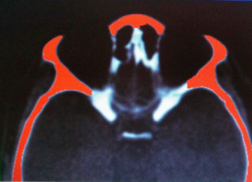
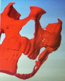
| − | X-Ray tomography data allowed damage evaluation from surgical procedure, and determined the volumetric space vacancy at the lower jaw (see Figure F2a). On the other hand, | + | X-Ray tomography data allowed damage evaluation from surgical procedure, and determined the volumetric space vacancy at the lower jaw (see Figure F2a). On the other hand, ScanIp® software was used to process 400 slices, so to develop patient's head. Figure F2b shows jaw resection and a simple chin that maintains the aesthetics and functionality of the remaining third branch of the jaw. |
Clinical studies of the patient were used to generate a personalised implant proposal. A review of jaw prosthesis available in the domestic and international markets allowed to establish some important parameters to be considered for the customised design of the jaw endo-prosthesis. The most important ones are: | Clinical studies of the patient were used to generate a personalised implant proposal. A review of jaw prosthesis available in the domestic and international markets allowed to establish some important parameters to be considered for the customised design of the jaw endo-prosthesis. The most important ones are: | ||
| Line 88: | Line 86: | ||
<li>Determination of the physical conditions of the receptor bone, considering permanent fixation. </li> | <li>Determination of the physical conditions of the receptor bone, considering permanent fixation. </li> | ||
<li>Material selection by physical and chemical characteristics to allow structural integrity and minimum wear. </li> | <li>Material selection by physical and chemical characteristics to allow structural integrity and minimum wear. </li> | ||
| − | <li>Natural external agent distribution into the jaw bone and | + | <li>Natural external agent distribution into the jaw bone and into the prosthesis. </li> |
</ol> | </ol> | ||
| − | It should be pointed out that jaw prosthesis service life is directly related to displacement, micro-movements and implant rotation. Thus, prostheses ought to have smooth surfaces and avoid sharp edges, in order to eliminate stress concentration into the implant and in the elements that should be used to fix the jaw prosthesis at the mandibular joint. Jaw prosthesis must be wider in the lateral direction, far away from the average | + | It should be pointed out that jaw prosthesis service life is directly related to displacement, micro-movements and implant rotation. Thus, prostheses ought to have smooth surfaces and avoid sharp edges, in order to eliminate stress concentration into the implant and in the elements that should be used to fix the jaw prosthesis at the mandibular joint. Jaw prosthesis must be wider in the lateral direction, far away from the average mid-line face; it should not be very rigid, have enough stability to control vibrations and should anticipate particle migration from the articulate surface towards the zygomatic area. Thus, this work allows the establishment of a criterion for the development of a personalised jaw prosthesis geometry. The initial geometry for the design of the implant is taken from X-Ray tomography data, to generate the working planes necessary for each mandibular bone area, as it is shown in Figure F2a. An exterior silhouette of the main mandibular geometry was developed, from which it was possible to obtain the bold dimensions of the implant, the main angles of the jaw and the internal relations of the condylar alignment. In the same way, a line is drawn that crosses through the centre of all the circumferences that wrap the jaw healthy body, so as to obtain the average curvature line and establish the maximum and minimum values for the teeth pieces alignment. |
<div id='img-2a'></div> | <div id='img-2a'></div> | ||
| Line 100: | Line 98: | ||
{| class="floating_imageSCP" style="text-align: center; border: 1px solid #BBB; margin: 1em auto; width: 100%;max-width: 100%;" | {| class="floating_imageSCP" style="text-align: center; border: 1px solid #BBB; margin: 1em auto; width: 100%;max-width: 100%;" | ||
|- | |- | ||
| − | |[[Image: | + | |[[Image:review_Torres-San-Miguel_et_al_2017a-F3a.png|186px|Mandibular resection.]] |
| − | |[[Image: | + | |[[Image:review_Torres-San-Miguel_et_al_2017a-F3b.png|168px|Reconstruction sagittal view.]] |
| − | |[[Image: | + | |[[Image:review_Torres-San-Miguel_et_al_2017a-F3c.png|198px|Inferior view of the mandibular bone alignment.]] |
|- style="text-align: center; font-size: 75%;" | |- style="text-align: center; font-size: 75%;" | ||
| − | | (a) Mandibular resection. | + | | (a) Mandibular resection. |
| − | | (b) Reconstruction sagittal view. | + | | (b) Reconstruction sagittal view. |
| − | | (c) Inferior view of the mandibular bone alignment. | + | | (c) Inferior view of the mandibular bone alignment. |
|- style="text-align: center; font-size: 75%;" | |- style="text-align: center; font-size: 75%;" | ||
| − | | colspan="3" | '''Figure 2:''' | + | | colspan="3" | '''Figure 2:''' Face-jaw model reconstruction. |
|} | |} | ||
| Line 117: | Line 115: | ||
{| class="floating_imageSCP" style="text-align: center; border: 1px solid #BBB; margin: 1em auto; width: 100%;max-width: 100%;" | {| class="floating_imageSCP" style="text-align: center; border: 1px solid #BBB; margin: 1em auto; width: 100%;max-width: 100%;" | ||
|- | |- | ||
| − | |[[Image: | + | |[[Image:review_Torres-San-Miguel_et_al_2017a-F4a.png|162px|3D Model of the patient.]] |
| − | |[[Image: | + | |[[Image:review_Torres-San-Miguel_et_al_2017a-F4b.png|216px|Partial jaw model.]] |
| − | |[[Image: | + | |[[Image:review_Torres-San-Miguel_et_al_2017a-F4c.png|174px|Final assembly of the implant.]] |
|- style="text-align: center; font-size: 75%;" | |- style="text-align: center; font-size: 75%;" | ||
| − | | (a) 3D Model of the patient. | + | | (a) 3D Model of the patient. |
| − | | (b) Partial jaw model. | + | | (b) Partial jaw model. |
| − | | (c) Final assembly of the implant. | + | | (c) Final assembly of the implant. |
|- style="text-align: center; font-size: 75%;" | |- style="text-align: center; font-size: 75%;" | ||
| colspan="3" | '''Figure 3''' | | colspan="3" | '''Figure 3''' | ||
|} | |} | ||
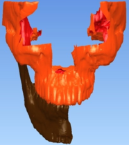
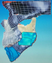
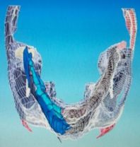
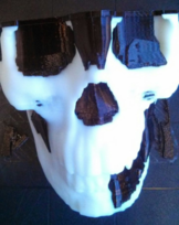
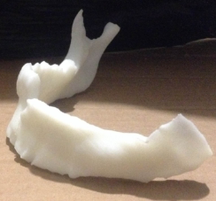
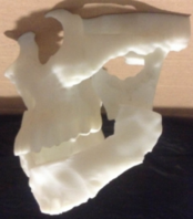
| − | In Figure F3a, a general view of the main model for the patient face deficiencies without the chin, is shown. This model is extremely important because the accuracy is a variable that | + | In Figure F3a, a general view of the main model for the patient face deficiencies without the chin, is shown. This model is extremely important because the accuracy is a variable that delimits the success of the patient's aesthetic. As mentioned by <span id='citeF-21'></span>[[#cite-21|[21]]], the manufacture by means of stereolithography shows some significant differences, but these are clinically irrelevant; for this reason, fused deposition modelling technique was used to evaluate the behaviour and assembly of mandibular endo-prosthesis (also see Figure [[#img-3|3]]). Figure F3b shows a sagittal view, where the simulation of the implant that will be placed at the mandibular joint is featured. In Figure F3c, an inferior view of the half jaw replacement can be appreciated, which also presents a better perspective of the new jaw prosthesis. This constitutes the model that will be used for FEM analyses. The model of the implant was built up with Powersheape®software, which allowed the development of a half mirror model of the missing jaw. It also allowed the construction of anchored zones for customised implant and the alignment of posts for the placement of teeth. |
| − | The jaw prosthesis was modelled with an ABS polymer before the reconstruction surgical procedure, in order to check the elements assembling. This polymer model allowed the simulation of one of the three-dimensional available designs of the jaw prosthesis. The 3D face bone model allowed the simulation of the face of the patient, so to identify areas that surgeon should cut off as well as space voids that should be filled up, thus, determining the best way to insert prosthesis. Additionally, useful information from the equipment to be used in the surgical procedure, | + | The jaw prosthesis was modelled with an ABS polymer before the reconstruction surgical procedure, in order to check the elements assembling. This polymer model allowed the simulation of one of the three-dimensional available designs of the jaw prosthesis. The 3D face bone model allowed the simulation of the face of the patient, so to identify areas that surgeon should cut off as well as space voids that should be filled up, thus, determining the best way to insert prosthesis. Additionally, useful information from the equipment to be used in the surgical procedure, consisting in data of the contact that should be generated to improve the union between the implant against the joint bone, were considered. In this way, it is possible to diagnose a treatment plan. This can only be possible by obtaining the anatomical model of the damaged area with X-Ray tomographic shots. |
It is important to mention, that for every clinical case, it is possible to design and develop a partial or complete prosthesis with this methodology. The later depends on patient, his pathology, patient's age and the medical surgeon indications in order to establish the best technology for the substitution of the bone structure that has been damaged. Nonetheless this advantages, our proposal results in a handcrafted procedure. Figure [[#img-3|3]] shows the use of fused deposition modelling technique to a 3D model. | It is important to mention, that for every clinical case, it is possible to design and develop a partial or complete prosthesis with this methodology. The later depends on patient, his pathology, patient's age and the medical surgeon indications in order to establish the best technology for the substitution of the bone structure that has been damaged. Nonetheless this advantages, our proposal results in a handcrafted procedure. Figure [[#img-3|3]] shows the use of fused deposition modelling technique to a 3D model. | ||
| Line 139: | Line 137: | ||
{| class="floating_imageSCP" style="text-align: center; border: 1px solid #BBB; margin: 1em auto; width: 100%;max-width: 100%;" | {| class="floating_imageSCP" style="text-align: center; border: 1px solid #BBB; margin: 1em auto; width: 100%;max-width: 100%;" | ||
|- | |- | ||
| − | |[[Image: | + | |[[Image:review_Torres-San-Miguel_et_al_2017a-F5a.png|204px|]] |
| − | |[[Image: | + | |[[Image:review_Torres-San-Miguel_et_al_2017a-F5b.png|150px|]] |
|- style="text-align: center; font-size: 75%;" | |- style="text-align: center; font-size: 75%;" | ||
| − | | (a) | + | | (a) |
| − | | (b) | + | | (b) |
|- style="text-align: center; font-size: 75%;" | |- style="text-align: center; font-size: 75%;" | ||
| colspan="2" | '''Figure 4:''' Different views of the developed lower jaw prosthesis. | | colspan="2" | '''Figure 4:''' Different views of the developed lower jaw prosthesis. | ||
| Line 152: | Line 150: | ||
===3.1 Numerical analysis=== | ===3.1 Numerical analysis=== | ||
| − | A numerical model is used to perform numerical analyses, for which is necessary to know the mandibular anatomic characteristics. Getting the model through X-Ray scans, simplifies and reduces time to generate the numerical simulation. In order to generate it, a simple transformation of scanned data is required, in order for them to be able to be used in FEM. In order to apply the later method, boundary conditions due to external agents ought to be determined. The loads that mouth muscles can exert during daily activities, can be estimated from two theories <span id='citeF- | + | A numerical model is used to perform numerical analyses, for which it is necessary to know the mandibular anatomic characteristics. Getting the model through X-Ray scans, simplifies and reduces time to generate the numerical simulation. In order to generate it, a simple transformation of scanned data is required, in order for them to be able to be used in FEM analysis. In order to apply the later method, boundary conditions due to external agents ought to be determined. The loads that mouth muscles can exert during daily activities, can be estimated from two theories <span id='citeF-22'></span><span id='citeF-23'></span><span id='citeF-24'></span><span id='citeF-25'></span><span id='citeF-26'></span>[[#cite-22|[22,23,24,25,26]]]: |
<ol> | <ol> | ||
| − | <li>The exerted load by the mouth muscle when contraction is proportional to its | + | <li>The exerted load by the mouth muscle when contraction is proportional to its cross section. </li> |
<li>The muscle contraction varies depending on the time of the activity. </li> | <li>The muscle contraction varies depending on the time of the activity. </li> | ||
| Line 171: | Line 169: | ||
| style="text-align: center;" | <math>{{M}_{ir}}=(\left({{\left(EMG \right)}_{Mi}}~ \right)\left({{X}_{Mi}}K \right)~{{M}_{ir}}</math> | | style="text-align: center;" | <math>{{M}_{ir}}=(\left({{\left(EMG \right)}_{Mi}}~ \right)\left({{X}_{Mi}}K \right)~{{M}_{ir}}</math> | ||
|- | |- | ||
| − | | style="text-align: center;" | <math>=\left({{\left(EMG \right)}_{Mi}}~ \right)\left({{X}_{Mi}}K \right) | + | | style="text-align: center;" | <math>=\left({{\left(EMG \right)}_{Mi}}~ \right)\left({{X}_{Mi}}K \right) </math> |
|} | |} | ||
| style="width: 5px;text-align: right;white-space: nowrap;" | (1) | | style="width: 5px;text-align: right;white-space: nowrap;" | (1) | ||
|} | |} | ||
| − | where: <math display="inline">K</math> refers to a physiologic constant, <math display="inline">X_{Mi}</math> refers to the muscle cross section, and <math display="inline">(EMG)_{Mi}</math> refers to the activity. The <math display="inline">K</math> value is considered as 40 N/cm<math display="inline">^2</math> <span id='citeF- | + | where: <math display="inline">K</math> refers to a physiologic constant, <math display="inline">X_{Mi}</math> refers to the muscle cross section, and <math display="inline">(EMG)_{Mi}</math> refers to the activity. The <math display="inline">K</math> value is considered as 40 N/cm<math display="inline">^2</math> <span id='citeF-23'></span>[[#cite-23|[23]]], independently of the age, sex and muscle of the person. There are studies where cross section of the muscle has been measured <span id='citeF-23'></span>[[#cite-23|[23]]]. Table [[#table-1|1]] shows average obtained values. |
{| class="floating_tableSCP wikitable" style="text-align: right; margin: 1em auto;min-width:50%;" | {| class="floating_tableSCP wikitable" style="text-align: right; margin: 1em auto;min-width:50%;" | ||
| − | |+ style="font-size: 75%;" |<span id='table-1'></span>Table. 1 Average values of chewing muscles <span id='citeF- | + | |+ style="font-size: 75%;" |<span id='table-1'></span>Table. 1 Average values of chewing muscles <span id='citeF-23'></span>[[#cite-23|[23]]]. |
|- | |- | ||
| style="text-align: left;" | '''Muscular group''' | | style="text-align: left;" | '''Muscular group''' | ||
| Line 208: | Line 206: | ||
| 174.8 | | 174.8 | ||
|- | |- | ||
| − | | rowspan=' | + | | rowspan='2' style="text-align: left;" | Temporal |
| rowspan='3' style="text-align: left;" | 8.23 | | rowspan='3' style="text-align: left;" | 8.23 | ||
| Anterior | | Anterior | ||
| Line 220: | Line 218: | ||
| 95.6 | | 95.6 | ||
|- | |- | ||
| + | | style="text-align: left;" | 3-6 | ||
| Posterior | | Posterior | ||
| 0.23 | | 0.23 | ||
| Line 246: | Line 245: | ||
|} | |} | ||
| − | The total average chewing load for all muscles is 911.6 N. The maximum anatomical chewing load corresponds to the maximum contractile power of the muscles when they open the jaw. The chewing load is calculated based on the relation between the load developed by a skeletal muscle and the muscular cross unit area. <span id='citeF- | + | The total average chewing load for all muscles is 911.6 N. The maximum anatomical chewing load corresponds to the maximum contractile power of the muscles when they open the jaw. The chewing load is calculated based on the relation between the load developed by a skeletal muscle and the muscular cross unit area. In <span id='citeF-27'></span>[[#cite-27|[27]]], authors reported that chewing load is between 210 to 400 kg (2060.1 to 3924 N). The numerical analysis presented in this work considered diverse parameters such as average maximum loads (i.e. that the load is uniformly distributed along the chewing line) and applied elastic, isotropic and homogeneous conditions. The numerical simulation was performed in a 3D model, with high order elements with 20 nodes. Figure [[#img-5|5]] shows applied boundary conditions at the edges of jaw implant, as well as the exerted loads. The used mechanical properties are those for Titanium (ELI) Grade 5 alloy alpha beta with 6% Al and 4% V, Young’s modulus 200 GPa, Poisson relation of 0.28 and a yield strength of 900 MPa <span id='citeF-28'></span>[[#cite-28|[28]]]. |
| − | + | ||
| − | + | ||
<div id='img-5'></div> | <div id='img-5'></div> | ||
{| class="floating_imageSCP" style="text-align: center; border: 1px solid #BBB; margin: 1em auto; width: 100%;max-width: 100%;" | {| class="floating_imageSCP" style="text-align: center; border: 1px solid #BBB; margin: 1em auto; width: 100%;max-width: 100%;" | ||
|- | |- | ||
| − | |[[Image: | + | |[[Image:review_Torres-San-Miguel_et_al_2017a-F6.png|360px|Loading and boundary conditions at the jaw prosthesis.]] |
|- style="text-align: center; font-size: 75%;" | |- style="text-align: center; font-size: 75%;" | ||
| colspan="1" | '''Figure 5:''' Loading and boundary conditions at the jaw prosthesis. | | colspan="1" | '''Figure 5:''' Loading and boundary conditions at the jaw prosthesis. | ||
|} | |} | ||
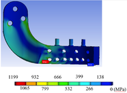
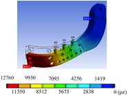
| − | von Misses stress and equivalent strain with an applied average load of 911.6 were calculated. Figure [[#img-6|6]] show total displacement, von Misses stress and equivalent strain of the implant when undergoing a maximum load of 3924 N. | + | Performed simulations required an intensive processing burden (50-60 minutes per simulation). Simulations results show the relation between the applied loads, the geometrical characteristics of material, the restrictions and deformations. von Mises theory to determine stress was used, in order to determine the stress distribution along the prosthesis. |
| + | |||
| + | ==4 Results== | ||
| + | |||
| + | Two study cases were analysed: a mandible himiprosthesis featuring screws to place teeth, and a second one without such screws. Developed von Misses stress and equivalent strain during the chewing cycle, i.e. with an applied average load of 911.6, were calculated. Figure [[#img-6|6]] show total displacement, von Misses stress and equivalent strain of the implant when undergoing a maximum load of 3924 N. With the previously mentioned load conditions, the numerical simulations obtained for both cases show the minimum and maximum stresses for the first right third of the mandible branch, where the anchorage with the mandibular bone is not considered. As it can be observed from Figure F7b, the obtained stresses does not exceed the yield strength of the material (900 MPa <span id='citeF-28'></span>[[#cite-28|[28]]]); clearly, the found values are below the yield strength of material, independently of the irregularities int he carpo zone and the mandibular branch. It also ought to be noted that the stress distribution is practically symmetric in the low and up parts of the maxillary angle. | ||
<div id='img-6a'></div> | <div id='img-6a'></div> | ||
| Line 266: | Line 267: | ||
{| class="floating_imageSCP" style="text-align: center; border: 1px solid #BBB; margin: 1em auto; width: 100%;max-width: 100%;" | {| class="floating_imageSCP" style="text-align: center; border: 1px solid #BBB; margin: 1em auto; width: 100%;max-width: 100%;" | ||
|- | |- | ||
| − | |[[Image: | + | |[[Image:review_Torres-San-Miguel_et_al_2017a-F7a.png|186px|Total displacement.]] |
| − | |[[Image: | + | |[[Image:review_Torres-San-Miguel_et_al_2017a-F7b.png|186px|von Misses stress.]] |
| − | |[[Image: | + | |[[Image:review_Torres-San-Miguel_et_al_2017a-F7c.png|186px|Strain.]] |
|- style="text-align: center; font-size: 75%;" | |- style="text-align: center; font-size: 75%;" | ||
| − | | (a) Total displacement. | + | | (a) Total displacement. |
| − | | (b) von Misses stress. | + | | (b) von Misses stress. |
| − | | (c) Strain. | + | | (c) Strain. |
|- style="text-align: center; font-size: 75%;" | |- style="text-align: center; font-size: 75%;" | ||
| − | | colspan="3" | '''Figure 6:''' Maximum loading results. | + | | colspan="3" | '''Figure 6:''' Maximum loading FEM results. |
|} | |} | ||
| − | + | The half-lower jaw prosthesis, showed in Figure [[#img-4|4]], was manufactured with a bio-compatible material (Titanium ELI) using only one piece and applying compression forces during the manufacturing process. The implant was modelled to provide a similar morphological pattern, which allow the optimal replacement of the mandibular resected bone. The endo-prosthesis has a series of holes to decrease prosthesis weight, without decreasing its structural integrity. One of its ends has the form of the mandibular notch and neck, allowing its connection to the condyle through an anchorage, that holds the condyle to the upper jaw. It is possible to apply this kind of attachment because the jaw angle depends on the morphological characteristics of the patient. Both ends of the prosthesis are screwed to the patient with surgical bolts, as it is shown in the Figure [[#img-7|7]]. | |
| − | + | ||
| − | The half-lower jaw prosthesis, showed in Figure [[#img-4|4]], was manufactured with a | + | |
<div id='img-7'></div> | <div id='img-7'></div> | ||
{| class="floating_imageSCP" style="text-align: center; border: 1px solid #BBB; margin: 1em auto; width: 100%;max-width: 100%;" | {| class="floating_imageSCP" style="text-align: center; border: 1px solid #BBB; margin: 1em auto; width: 100%;max-width: 100%;" | ||
|- | |- | ||
| − | |[[Image: | + | |[[Image:review_Torres-San-Miguel_et_al_2017a-F8.png|270px|New half lower jaw prosthesis attache into the model.]] |
|- style="text-align: center; font-size: 75%;" | |- style="text-align: center; font-size: 75%;" | ||
| − | | colspan="1" | '''Figure 7:''' New half lower jaw prosthesis | + | | colspan="1" | '''Figure 7:''' New half lower jaw prosthesis attache into the model. |
|} | |} | ||
Results from the numerical simulation show that von Misses stresses, strains and total displacements are low when an average chewing load is applied. These are under the mechanical risk zone that Titanium could undertake, so the implant should work properly under normal chewing conditions. If the chewing load reaches a maximum value, the implant should work just under its mechanical yield zone; so if the patient is exposed to this condition it would not reach a critical value. Nevertheless, several physiological and physical factors would not permit to reach the maximum load. | Results from the numerical simulation show that von Misses stresses, strains and total displacements are low when an average chewing load is applied. These are under the mechanical risk zone that Titanium could undertake, so the implant should work properly under normal chewing conditions. If the chewing load reaches a maximum value, the implant should work just under its mechanical yield zone; so if the patient is exposed to this condition it would not reach a critical value. Nevertheless, several physiological and physical factors would not permit to reach the maximum load. | ||
| − | ==5 | + | ==5 Discussion== |
In this work, a personalised half lower jaw prosthesis using X-Ray tomography and a fused deposition modelling technique, was developed. The prosthesis was successfully implanted in Mexico, to a patient suffering jaw bone cancer, as it is shown in Figure [[#img-8|8]]. The surgery procedure, performed to the patient, was to partially amputate the mandibular bone. The innovation presented in this work, is the application of 3D technology (modelling) to reconstruct half of the lower mandibular bone by inserting an endo-prosthesis. | In this work, a personalised half lower jaw prosthesis using X-Ray tomography and a fused deposition modelling technique, was developed. The prosthesis was successfully implanted in Mexico, to a patient suffering jaw bone cancer, as it is shown in Figure [[#img-8|8]]. The surgery procedure, performed to the patient, was to partially amputate the mandibular bone. The innovation presented in this work, is the application of 3D technology (modelling) to reconstruct half of the lower mandibular bone by inserting an endo-prosthesis. | ||
| − | As mentioned by <span id='citeF- | + | As mentioned by <span id='citeF-29'></span>[[#cite-29|[29]]], computer-assisted procedures have proven to be effective methods to obtain dental alignment between the upper and lower jaw. Nevertheless, as in this work the developed prosthesis was customised, it naturally provides a correct alignment with the face structure and with the healthy mandibular bone. Additionally, prosthetic teeth can be attached to tolerate normal chewing. Also, the customisation of the prosthesis should allow a better life quality to the patient. The development of this prosthesis can be used to tackle three different mandibular bone deficiencies: as an artificial condyle, as a band for the substitution of the principal jaw bone and as a strip band for an additional fixation member. |
<div id='img-8a'></div> | <div id='img-8a'></div> | ||
| Line 302: | Line 301: | ||
{| class="floating_imageSCP" style="text-align: center; border: 1px solid #BBB; margin: 1em auto; width: 100%;max-width: 100%;" | {| class="floating_imageSCP" style="text-align: center; border: 1px solid #BBB; margin: 1em auto; width: 100%;max-width: 100%;" | ||
|- | |- | ||
| − | |[[Image: | + | |[[Image:review_Torres-San-Miguel_et_al_2017a-F9a.png|192px|Frontal plane.]] |
| − | |[[Image: | + | |[[Image:review_Torres-San-Miguel_et_al_2017a-F9b.png|186px|Cross plane.]] |
|- style="text-align: center; font-size: 75%;" | |- style="text-align: center; font-size: 75%;" | ||
| − | | (a) Frontal plane. | + | | (a) Frontal plane. |
| − | | (b) | + | | (b) Cross plane. |
|- style="text-align: center; font-size: 75%;" | |- style="text-align: center; font-size: 75%;" | ||
| colspan="2" | '''Figure 8:''' Jaw surgery. | | colspan="2" | '''Figure 8:''' Jaw surgery. | ||
|} | |} | ||
| − | + | As for the surgical recovery period, the first stage, once after the patient has recovered from surgical medic process (organ stabilisation), consists on evaluating and attending the functional and aesthetic consequences of the procedure. In the case of the lower jaw loss, the immediate consequences are related to the respiratory, the digestive and the vocal systems, as well as to the evolution of organ reactions depending on sleeping. The prosthesis restitution implies, first of all, the recovery of organ systems and basic functions, from the medical point of view. From the patient's point of view, it is important to restore a natural aesthetic appearance, which could bring confidence to the person. Within this first stage, there is a consensual solution for both parts (medical and patient): the prosthetic implant must adjust to the biological appearance and perform the required functions. The new low jaw prosthesis developed in this paper, is aimed to provide both functions. | |
| − | + | In the second stage of recovery, the manufactured prosthesis should be refined and detailed for the customisation for the patient and his requirements <span id='citeF-30'></span>[[#cite-30|[30]]]. Although in most cases, health carers perform three-dimensional soft tissue modelling of chin, for implementing an aesthetics treatment, in this case the prosthetic implant has already been personalised to suit morphological aspects of the patient. So it is expected that the prosthesis integration occurs in a natural manner to the respiratory and digestive biological processes. Additionally, it should not hinder its integration to adjacent organs (tongue, teeth, trachea, chew, etc.). Within the aesthetic aspect, the general integration should arise in patient's mind. The total recovery after surgery should provide confidence to the patient and his face should match or be very similar to the one before surgery, conserving his face symmetry, without cosmetics factors, and his functions should work properly. | |
| − | In | + | In a third and last recovery stage, the application and normal service (rehabilitation) of the prosthesis was assessed. Prosthesis should be analysed and corrected, in case of any collateral effects, organ adjustments (life of the prosthesis), as well as not working properly, inherently. Cosmetic variations must be determined (ageing in comparison to prosthetic), which could require adjustment interventions. These should be easy, due to the prosthesis design herein developed. |
| − | + | ==6 Conclusion== | |
| − | + | This research deals with a system of metal mandibular prosthesis for patients who have undergone a subtotal resection hemimandibulectomy. This prosthesis was developed in order to restore damaged functions when the lower part of the jaw was injured by tumour cancer. The presented metal mandibular prosthesis provides consolidation, hygiene and easiness in bone implant, which is able of respond to a partial resection without affecting the jaw or temporomandibular joint condyle, the replacement of teeth. The prosthesis have three mobility axes: X, Y and Z rotatory capacity, simulating natural bite. It also provides aesthetic volume and it gives volume and tone to facial muscles in order to provide an adaptation to any patient's morphological geometry. Although designed for humans, the procedure herein developed to design and manufacture jaw prosthesis could be easily extended for its usage in veterinary area. | |
| − | + | ||
| − | This research deals with a system of metal mandibular prosthesis for patients who have undergone a subtotal resection hemimandibulectomy. This prosthesis was developed in order to restore damaged functions when part of the jaw was injured by tumour cancer. | + | |
==Acknowledgements:== | ==Acknowledgements:== | ||
| − | The authors gratefully acknowledge the financial support from the Mexican government by Consejo Nacional de Ciencia y Tecnología, to the Instituto Politécnico Nacional and the biomechanics group of INSIA from the Universidad Politécnica of Madrid. Authors also acknowledge partial support projects 20181139, 20180472, 20181441, 20181028, 20181141, as well as EDI grant, all provided by SIP/IPN. | + | The authors gratefully acknowledge the financial support from the Mexican government by Consejo Nacional de Ciencia y Tecnología, to the Instituto Politécnico Nacional and the biomechanics group of INSIA from the Universidad Politécnica of Madrid. Authors also acknowledge partial support projects 20181139, 20180472, 20181441, 20181028, 20181141, 20195634, 20195343, 20190136, 20196710, and 1930, as well as EDI grant, all provided by SIP/IPN. |
==Conflict of Interest== | ==Conflict of Interest== | ||
| Line 334: | Line 331: | ||
<div id="cite-1"></div> | <div id="cite-1"></div> | ||
| − | '''[[#citeF-1|[1]]]''' | + | '''[[#citeF-1|[1]]]''' Guarda-Nardini, L and Manfredini, D and Ferronato, G. (2008) "Temporomandibular joint total replacement prosthesis: current knowledge and considerations for the future", Volume 37. Elsevier. International journal of oral and maxillofacial surgery 2 103–110 |
<div id="cite-2"></div> | <div id="cite-2"></div> | ||
| − | '''[[#citeF-2|[2]]]''' | + | '''[[#citeF-2|[2]]]''' Madsen, Matthew J and Haug, Richard H. (2006) "A biomechanical comparison of 2 techniques for reconstructing atrophic edentulous mandible fractures", Volume 64. Elsevier. Journal of oral and maxillofacial surgery 3 457–465 |
<div id="cite-3"></div> | <div id="cite-3"></div> | ||
| − | '''[[#citeF-3|[3]]]''' | + | '''[[#citeF-3|[3]]]''' Tideman, H and Samman, N and Cheung, LK. (1998) "Functional reconstruction of the mandible: a modified titanium mesh system", Volume 27. Elsevier. International journal of oral and maxillofacial surgery 5 339–345 |
<div id="cite-4"></div> | <div id="cite-4"></div> | ||
| − | '''[[#citeF-4|[4]]]''' | + | '''[[#citeF-4|[4]]]''' Maki, K and Miller, AJ and Okano, T and Shibasaki, Y. (2001) "A three-dimensional, quantitative computed tomographic study of changes in distribution of bone mineralization in the developing human mandible", Volume 46. Elsevier. Archives of Oral biology 7 667–678 |
<div id="cite-5"></div> | <div id="cite-5"></div> | ||
| − | '''[[#citeF-5|[5]]]''' | + | '''[[#citeF-5|[5]]]''' Torreira, Mercedes GALLAS and Fernandez, Jose Ramon. (2004) "A three-dimensional computer model of the human mandible in two simulated standard trauma situations", Volume 32. Elsevier. Journal of Cranio-Maxillofacial Surgery 5 303–307 |
<div id="cite-6"></div> | <div id="cite-6"></div> | ||
| − | '''[[#citeF-6|[6]]]''' | + | '''[[#citeF-6|[6]]]''' Seper, László and Piffkó, József and Joos, Ulrich and Meyer, Ulrich. (2004) "Treatment of fractures of the atrophic mandible in the elderly", Volume 52. Wiley Online Library. Journal of the American Geriatrics Society 9 1583–1584 |
<div id="cite-7"></div> | <div id="cite-7"></div> | ||
| − | '''[[#citeF-7|[7]]]''' | + | '''[[#citeF-7|[7]]]''' Nagasao, Tomohisa and Miyamoto, Junpei and Tamaki, Tamotsu and Kawana, Hiromasa. (2010) "A comparison of stresses in implantation for grafted and plate-and-screw mandible reconstruction", Volume 109. Elsevier. Oral Surgery, Oral Medicine, Oral Pathology, Oral Radiology, and Endodontology 3 346–356 |
<div id="cite-8"></div> | <div id="cite-8"></div> | ||
| − | '''[[#citeF-8|[8]]]''' | + | '''[[#citeF-8|[8]]]''' Bak, Mathew and Jacobson, Adam S and Buchbinder, Daniel and Urken, Mark L. (2010) "Contemporary reconstruction of the mandible", Volume 46. Elsevier. Oral oncology 2 71–76 |
<div id="cite-9"></div> | <div id="cite-9"></div> | ||
| − | '''[[#citeF-9|[9]]]''' | + | '''[[#citeF-9|[9]]]''' Katsuragi, Yoko and Kayano, Shuji and Akazawa, Satoshi and Nagamatsu, Shogo and Koizumi, Takuya and Matsui, Takahiro and Onitsuka, Tetsuro and Yurikusa, Takashi and Huang, Wei-Chao and Nakagawa, Masahiro. (2011) "Mandible reconstruction using the calcium-sulphate three-dimensional model and rubber stick: a new method,‘mould technique’, for more accurate, efficient and simplified fabrication", Volume 64. Elsevier. Journal of Plastic, Reconstructive & Aesthetic Surgery 5 614–622 |
<div id="cite-10"></div> | <div id="cite-10"></div> | ||
| − | '''[[#citeF-10|[10]]]''' | + | '''[[#citeF-10|[10]]]''' Clason, Christian and Hinz, Andreas M and Schieferstein, Heinrich. (2004) "A method for material parameter determination for the human mandible based on simulation and experiment", Volume 7. Taylor & Francis. Computer methods in biomechanics and biomedical engineering 5 265–276 |
<div id="cite-11"></div> | <div id="cite-11"></div> | ||
| − | '''[[#citeF-11|[11]]]''' | + | '''[[#citeF-11|[11]]]''' Del Palomar, A Perez and Doblaré, M. (2006) "Finite element analysis of the temporomandibular joint during lateral excursions of the mandible", Volume 39. Elsevier. Journal of Biomechanics 12 2153–2163 |
<div id="cite-12"></div> | <div id="cite-12"></div> | ||
| − | '''[[#citeF-12|[12]]]''' | + | '''[[#citeF-12|[12]]]''' Simon, ENM and Merkx, MAW and Shubi, FM and Kalyanyama, BM and Stoelinga, PJW. (2006) "Reconstruction of the mandible after ablative surgery for the treatment of aggressive, benign odontogenic tumours in Tanzania: a preliminary study", Volume 35. Elsevier. International journal of oral and maxillofacial surgery 5 421–426 |
<div id="cite-13"></div> | <div id="cite-13"></div> | ||
| − | '''[[#citeF-13|[13]]]''' | + | '''[[#citeF-13|[13]]]''' Liao, Sheng-Hui and Tong, Ruo-Feng and Dong, Jin-Xiang. (2007) "Anisotropic finite element modeling for patient-specific mandible", Volume 88. Elsevier. Computer methods and programs in biomedicine 3 197–209 |
<div id="cite-14"></div> | <div id="cite-14"></div> | ||
| − | '''[[#citeF-14|[14]]]''' | + | '''[[#citeF-14|[14]]]''' Buchaillard, Stéphanie and Brix, Muriel and Perrier, Pascal and Payan, Yohan. (2007) "Simulations of the consequences of tongue surgery on tongue mobility: implications for speech production in post-surgery conditions", Volume 3. Wiley Online Library. The International Journal of Medical Robotics and Computer Assisted Surgery 3 252–261 |
<div id="cite-15"></div> | <div id="cite-15"></div> | ||
| − | '''[[#citeF-15|[15]]]''' | + | '''[[#citeF-15|[15]]]''' Manolidis, Spiros. (2000) "Modular mandibular prosthesis". Google Patents |
<div id="cite-16"></div> | <div id="cite-16"></div> | ||
| − | '''[[#citeF-16|[16]]]''' | + | '''[[#citeF-16|[16]]]''' Gordon, Jeffrey D. (1996) "Apparatus for total temporomandibular joint replacement". Google Patents |
<div id="cite-17"></div> | <div id="cite-17"></div> | ||
| − | '''[[#citeF-17|[17]]]''' | + | '''[[#citeF-17|[17]]]''' Nealis, Michael F. (1995) "Temporomandibular joint prosthesis". Google Patents |
<div id="cite-18"></div> | <div id="cite-18"></div> | ||
| − | '''[[#citeF-18|[18]]]''' | + | '''[[#citeF-18|[18]]]''' Collins, Thomas A. (1988) "Mandibular prosthesis". Google Patents |
<div id="cite-19"></div> | <div id="cite-19"></div> | ||
| − | '''[[#citeF-19|[19]]]''' | + | '''[[#citeF-19|[19]]]''' Touleimat, Saad and Touleimat, Abdul-Elah. (2014) "Adjustable mandible joint system". Google Patents |
<div id="cite-20"></div> | <div id="cite-20"></div> | ||
| − | '''[[#citeF-20|[20]]]''' | + | '''[[#citeF-20|[20]]]''' Van Loon, Jan-paul. (1999) "Adjustable temporomandibular surgical implant". Google Patents |
<div id="cite-21"></div> | <div id="cite-21"></div> | ||
| − | '''[[#citeF-21|[21]]]''' | + | '''[[#citeF-21|[21]]]''' Camardella, Leonardo Tavares and Vilella, Oswaldo V and van Hezel, Marleen M and Breuning, Karel H. (2017) "Accuracy of stereolithographically printed digital models compared to plaster models". Springer. Journal of Orofacial Orthopedics/Fortschritte der Kieferorthopädie 1–9 |
<div id="cite-22"></div> | <div id="cite-22"></div> | ||
| − | '''[[#citeF-22|[22]]]''' | + | '''[[#citeF-22|[22]]]''' Pruim, GJ and De Jongh, HJ and Ten Bosch, JJ. (1980) "Forces acting on the mandible during bilateral static bite at different bite force levels", Volume 13. Elsevier. Journal of biomechanics 9 755–763 |
<div id="cite-23"></div> | <div id="cite-23"></div> | ||
| − | '''[[#citeF-23|[23]]]''' | + | '''[[#citeF-23|[23]]]''' Weijs, WA and Hillen, B. (1984) "Relationship between the physiological cross-section of the human jaw muscles and their cross-sectional area in computer tomograms", Volume 118. Karger Publishers. Cells Tissues Organs 3 129–138 |
<div id="cite-24"></div> | <div id="cite-24"></div> | ||
| − | '''[[#citeF-24|[24]]]''' J.W.C. MacDonald and A.G. Hannam. (1984) "Relationship between occlusal contacts and jaw-closing muscle activity during tooth clenching: Part | + | '''[[#citeF-24|[24]]]''' J.W.C. MacDonald and A.G. Hannam. (1984) "Relationship between occlusal contacts and jaw-closing muscle activity during tooth clenching: Part I", Volume 52. The Journal of Prosthetic Dentistry 5 718 - 729 |
<div id="cite-25"></div> | <div id="cite-25"></div> | ||
| − | '''[[#citeF-25|[25]]]''' | + | '''[[#citeF-25|[25]]]''' J.W.C. MacDonald and A.G. Hannam. (1984) "Relationship between occlusal contacts and jaw-closing muscle activity during tooth clenching: Part II", Volume 52. The Journal of Prosthetic Dentistry 6 862 - 867 |
<div id="cite-26"></div> | <div id="cite-26"></div> | ||
| − | '''[[#citeF-26|[26]]]''' | + | '''[[#citeF-26|[26]]]''' E. Moller. (1996) "The chewing apparatus; An electomyographic study of the action of the muscles of mastication and its correlation to facial morphology", Volume 280. Acta Physiological Scandinavian Supplement 1-229 |
<div id="cite-27"></div> | <div id="cite-27"></div> | ||
| − | '''[[#citeF-27|[27]]]''' | + | '''[[#citeF-27|[27]]]''' G. Nelson. (1986) "Three dimensional Computer modeling of human mandibular biomechanics". The university of British Columbia 201-226 |
<div id="cite-28"></div> | <div id="cite-28"></div> | ||
| − | '''[[#citeF-28|[28]]]''' | + | '''[[#citeF-28|[28]]]''' Lütjering, G and Williams, JC and Gysler, A. (2000) "MICROSTRUCTURE AND MECHANICAL PROPERTIES OF TITANIUM ALLOYS". Microstructure And Properties Of Materials: (Volume 2). World Scientific 1-77 |
<div id="cite-29"></div> | <div id="cite-29"></div> | ||
| − | '''[[#citeF-29|[29]]]''' Holberg, Christof and Heine, Anne-Kathrin and Geis, Philipp and Schwenzer, Katja and Rudzki-Janson, Ingrid. (2005) "Three-dimensional soft tissue prediction using finite elements", Volume 66. Springer. Journal of Orofacial Orthopedics/Fortschritte der Kieferorthopädie 2 122–134 | + | '''[[#citeF-29|[29]]]''' Zizelmann, C and Bucher, P and Rohner, D and Gellrich, N-C and Kokemueller, H and Hammer, B. (2010) "Virtual restoration of anatomic jaw relationship to obtain a precise 3D model for total joint prosthesis construction for treatment of TMJ ankylosis with open bite", Volume 39. Elsevier. International journal of oral and maxillofacial surgery 10 1012–1015 |
| + | |||
| + | <div id="cite-30"></div> | ||
| + | '''[[#citeF-30|[30]]]''' Holberg, Christof and Heine, Anne-Kathrin and Geis, Philipp and Schwenzer, Katja and Rudzki-Janson, Ingrid. (2005) "Three-dimensional soft tissue prediction using finite elements", Volume 66. Springer. Journal of Orofacial Orthopedics/Fortschritte der Kieferorthopädie 2 122–134 | ||
Revision as of 05:58, 4 February 2019
Abstract
In this work, design, manufacture and surgical success of a personalised temporomandibular prosthesis is featured. A fused deposition modelling technique and Die forging process constitute the methodology used in a patient who had an amputation in the upper third branch of the mandible, without considering the joint capsule. The implant was designed using a processed resection image of a computational tomography and using the methodology of zkaya and Nordin. The jaw operating conditions were simulated by the finite element method (FEM). The main considered factors were the morphological geometry of the patient, implant fixation in the first third of the branch, implant fixation on the chin, dental post for placement of the teeth, and the form of the sub-lingual fossa weight optimisation. Special consideration was to preserve the patients facial aesthetics.
Keywords: CAD|CAM; Custom prosthesis; FDM; FEM; Digital temporomandibular models;
2 Introduction
Consequences of deceases are diverse, and might lead to total or partial loss of a member by amputation, that can significantly affect the patient. The replacement of an organ or a member with prosthesis can represent, for the person, a recovery of an aptitude to perform different tasks and even organic basic functions. According to [1], psycho-social aspects toughen the patient in the recovery phase from surgery, mainly do to the number of successful - or not - surgical procedures. Such psycho-social deterioration is sometimes more incapacitating than the perception of the efficiency of undertaken surgical approach. Besides psycho-social, aesthetic aspects also affect the patient. All these factors contribute to his quality of life.
In the case of low jaw, important factors to be considered to select the best method to reconstruct it could be the patient psychological aspects, the affecting disease, the expected quality of life, the age, height and weight of the jaw bone, the state of teeth, etc. It is also important to grant aesthetic aspects to the face in order to reinforce the natural person's confidence. Nevertheless, even with technological advances, complications in chewing, deficient sensing, infections, and weakness in the strength of the face structure are prone to exist.
Much research has been done in the field of low jaw reconstruction. From open academic literature, the biomedical comparison between fixing a Titanium plate to the lateral edge of the jaw as well as to the low jaw edge is reported by [2], finding significant differences in the implant's mechanical behaviour. In [3], authors manufacture a replacement with specific measures of the patient's jaw, obtained prior to surgical procedure, yielding to a prosthesis which is very close to the original bone configuration of the patient. A 3D study, from tomographic resources, was developed by [4], which allowed to determine the existence of mineralisation of the cortical bone distribution part. Additionally, in [5], authors applied a 3D model to known the mechanical behaviour of the jaw, determining that it bears a load up to 107N/m. This loading condition is generated by impact, and could lead to fractures at low jaw [5]. An anosteosynthesis plate for an atrophic jaw, by using a mono cortical osteosynthesis of 2 Titanium plates was developed by [6]. On the other side, it has been shown that a subjection element at the plate produces a better behaviour at the connection implant when chewing than other positions of implant subjection elements for grafts implants [7]. Also, in [8], authors performed a jaw reconstruction by means of free human tissue transfer, concluding that the main parts are iliac and scapula, which allow the mobility of the tongue, so they have to be considered in jaw reconstruction. Authors of [9] analysed jaw reconstruction using 3D models of calcium in order to manufacture a physical model of jaw prosthesis, by considering that performing a pre-operational analysis, should allow more accurate reconstruction plates improving implant alignment.
In the side of applying numerical tools of engineering to the problem, also much research has been done. In [10], authors developed a study to determine the human jaw elastic response, by using finite element algorithms derived from mechanical loads. In the same mood, lateral movement of jaw, as well as collateral ligaments that connect articulate discs to condyle poles was simulated by Finite Element Method (FEM) [11]. The later study determined that the function of temporomandibular ligament is to guide jaw during its motion. In other study, vascular micro-grafts were used to reconstruct an atrophied due to a tumour extraction, concluding that bone grafts immediately inserted after resection could be better treated for these types of tumours [12]. In [13], authors performed a complete jaw numerical analysis by FEM; the model construction was estimated by contour conditions, the loading settings and the jaw limit displacement circumstances. Finally, authors of [14] developed the numerical analysis of a 3D biomechanical model of the oral cavity to predict consequences of tongue surgery on tongue movements, according to the size and location of the lost tissue, as well as the nature of the flap used by the surgeon.
In the field of patents, a wide range of geometries and morphologies of implants that aid in the treatment of diverse pathologies, have been reported. A modular type of mandibular prosthesis used for jaw resection, which considers the replacement of the jaw bone, by analysing the total jaw angle was proposed by [15]. The later prosthesis was developed by a sub-application of a couple of plates and a set of links used as connector elements. In [16], authors proposes a bio-compatible prosthetic device for the replacement of temporomandibular joint, which contemplates the substitution of the condyle neck, the condyle, as well as condyle pit; this device includes a convex spherical surface condyle component of the first radio for the substitution of the articulate surface of the condyle head. A new fixation method, that allows a free rotation of the elements in a portion at the edge that surrounds the fixation protuberance, over a bolted extreme neck that extends from the fixed plate to the mandibular, was developed by [17]. In such research, the plate has fixation slits to be anchored to jaw, allowing the adjustment in length, angle and shape of the mandible, allowing a much better performance. Authors of [18] show a mandibular prosthesis design, for its usage when jaw bone resection of condyle. It includes four holding elements to the mandibular body, to maintain jaw angle's geometry; these are separated by a distance similar to the thickness of the jaw. On the other hand, a prosthesis consisting of an adjustment screw aligned to the body of the jaw, which allows to modify its length, was presented by [19]. This prosthesis is for cases of orthognathic surgery, in order to align jaw and maxilla. The later device is fixed to the mandible using infra-osseous plates and screws. The prosthesis angle can be modified between 90 to 150 degrees, which allows to consider patient's anatomy, based on tomographic studies. Finally, a case of a total jaw implant, designed and manufactured using stereo-lithographic techniques, is featured in [20]. This prosthesis contains a hidroxyapatite layer and additives in the condyle zone, while the mandibular body contains a series of spaces, to decrease the implant weight. This prosthesis allows guiding of the facial nerve through the configuration channel.
This work is focused on the development of customised design of implants used for the partial restitution of jaw applied to a Mexican patient of medium age, who underwent cancer. A multidisciplinary solution was developed, applying engineering mechanical tools, medical surgery advanced techniques, X-Ray tomography data, FEM simulations and a fused deposition modelling technique, in order to optimise a forging manufacturing process, to produce customised lower jaw prosthesis. This work is organised as follows: in Section 3 the clinical background as well as materials and methods used in this work, including the description of the numerical analyses (FEM) herein performed (Subsection 3.1), are provided. In section 4 the results are shown, while in Section 5 concluding remarks along with a profuse discussion on the results obtained is shown.
3 Background, methods and materials
As background, a male person around 40 years old came to an ordinary dentist appointment suffering from an apparent uncontrollable molar pain. The dentist treated the pain and took an X-Ray tomographic slice, where a bone tumour was found. The present research started with the X-Ray tomography study and the biopsy analysis. After an extensive evaluation, a bone cancer tumour was determined to be the cause of pain. The bone tumour had a cystic aspect, osteolytic, multi-ocular, with well-defined and clear edges, of approximately 6 cm long and 3 cm height and located at the left lower jaw size. The tumour was extracted surgically, by a mandibulectomy or jaw resection. It was necessary to place a Titanium chin support in order to avoid a collapse in the muscles and face tissue.
Thus, an implant that could avoid deformation of the mandibular tissue and dropping of the face muscles, was required. It was necessary to prevent an misalignment of teeth so as to facilitate the daily activities (speech in a normal way, chewing, feeding, swallowing). This is a regular situation when facing a partial lost of the mandible bone due to the extraction of a cancer tumour.
|
|
| (a) Cross view of Computer Axial Tomography Reconstruction. | (b) 3D model reconstruction. |
| Figure 1: X-Ray tomography process. | |
X-Ray tomography data allowed damage evaluation from surgical procedure, and determined the volumetric space vacancy at the lower jaw (see Figure F2a). On the other hand, ScanIp® software was used to process 400 slices, so to develop patient's head. Figure F2b shows jaw resection and a simple chin that maintains the aesthetics and functionality of the remaining third branch of the jaw.
Clinical studies of the patient were used to generate a personalised implant proposal. A review of jaw prosthesis available in the domestic and international markets allowed to establish some important parameters to be considered for the customised design of the jaw endo-prosthesis. The most important ones are:
- Jaw prosthesis anatomy, which had to be adapted to the biomechanics of the joint (Zygomatic bone diameter, jaw bone transverse and longitudinal section).
- Jaw component orientation.
- Variations in the cross section of the central third jaw bone.
- Anchorage surface between jaw bone and joint.
- The necessity of no displacement between jaw bone and joint.
- Determination of static, dynamic and fatigue loads by analysing the jaw prosthesis curvature.
- Anti-rotation effect.
- Determination of the physical conditions of the receptor bone, considering permanent fixation.
- Material selection by physical and chemical characteristics to allow structural integrity and minimum wear.
- Natural external agent distribution into the jaw bone and into the prosthesis.
It should be pointed out that jaw prosthesis service life is directly related to displacement, micro-movements and implant rotation. Thus, prostheses ought to have smooth surfaces and avoid sharp edges, in order to eliminate stress concentration into the implant and in the elements that should be used to fix the jaw prosthesis at the mandibular joint. Jaw prosthesis must be wider in the lateral direction, far away from the average mid-line face; it should not be very rigid, have enough stability to control vibrations and should anticipate particle migration from the articulate surface towards the zygomatic area. Thus, this work allows the establishment of a criterion for the development of a personalised jaw prosthesis geometry. The initial geometry for the design of the implant is taken from X-Ray tomography data, to generate the working planes necessary for each mandibular bone area, as it is shown in Figure F2a. An exterior silhouette of the main mandibular geometry was developed, from which it was possible to obtain the bold dimensions of the implant, the main angles of the jaw and the internal relations of the condylar alignment. In the same way, a line is drawn that crosses through the centre of all the circumferences that wrap the jaw healthy body, so as to obtain the average curvature line and establish the maximum and minimum values for the teeth pieces alignment.
|
|
|
| (a) Mandibular resection. | (b) Reconstruction sagittal view. | (c) Inferior view of the mandibular bone alignment. |
| Figure 2: Face-jaw model reconstruction. | ||
|
|
|
| (a) 3D Model of the patient. | (b) Partial jaw model. | (c) Final assembly of the implant. |
| Figure 3 | ||
In Figure F3a, a general view of the main model for the patient face deficiencies without the chin, is shown. This model is extremely important because the accuracy is a variable that delimits the success of the patient's aesthetic. As mentioned by [21], the manufacture by means of stereolithography shows some significant differences, but these are clinically irrelevant; for this reason, fused deposition modelling technique was used to evaluate the behaviour and assembly of mandibular endo-prosthesis (also see Figure 3). Figure F3b shows a sagittal view, where the simulation of the implant that will be placed at the mandibular joint is featured. In Figure F3c, an inferior view of the half jaw replacement can be appreciated, which also presents a better perspective of the new jaw prosthesis. This constitutes the model that will be used for FEM analyses. The model of the implant was built up with Powersheape®software, which allowed the development of a half mirror model of the missing jaw. It also allowed the construction of anchored zones for customised implant and the alignment of posts for the placement of teeth.
The jaw prosthesis was modelled with an ABS polymer before the reconstruction surgical procedure, in order to check the elements assembling. This polymer model allowed the simulation of one of the three-dimensional available designs of the jaw prosthesis. The 3D face bone model allowed the simulation of the face of the patient, so to identify areas that surgeon should cut off as well as space voids that should be filled up, thus, determining the best way to insert prosthesis. Additionally, useful information from the equipment to be used in the surgical procedure, consisting in data of the contact that should be generated to improve the union between the implant against the joint bone, were considered. In this way, it is possible to diagnose a treatment plan. This can only be possible by obtaining the anatomical model of the damaged area with X-Ray tomographic shots.
It is important to mention, that for every clinical case, it is possible to design and develop a partial or complete prosthesis with this methodology. The later depends on patient, his pathology, patient's age and the medical surgeon indications in order to establish the best technology for the substitution of the bone structure that has been damaged. Nonetheless this advantages, our proposal results in a handcrafted procedure. Figure 3 shows the use of fused deposition modelling technique to a 3D model.
|
|
| (a) | (b) |
| Figure 4: Different views of the developed lower jaw prosthesis. | |
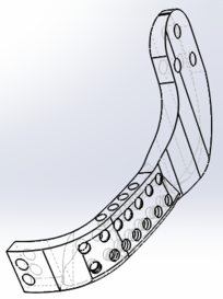
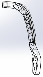
The new lower jaw implant shows a prosthesis device that should allow the patient to maintain his teeth, bite, eat, swallow, as well as a correct alignment. Figure 4 shows jaw prosthesis. This device was generated from computer X-Ray tomography taken from the patient, which helped to determine specific and personal data, so to generate the optimised solution for the person. The principal advantage is the obtainment of customised prosthesis that considers the patient's morphological geometry, as well as a specific suitable fixation between condyles and chin.
3.1 Numerical analysis
A numerical model is used to perform numerical analyses, for which it is necessary to know the mandibular anatomic characteristics. Getting the model through X-Ray scans, simplifies and reduces time to generate the numerical simulation. In order to generate it, a simple transformation of scanned data is required, in order for them to be able to be used in FEM analysis. In order to apply the later method, boundary conditions due to external agents ought to be determined. The loads that mouth muscles can exert during daily activities, can be estimated from two theories [22,23,24,25,26]:
- The exerted load by the mouth muscle when contraction is proportional to its cross section.
- The muscle contraction varies depending on the time of the activity.
So, the resulting load that the mouth muscle is able to apply during its contraction is described as ():
|
|
(1) |
where: refers to a physiologic constant, refers to the muscle cross section, and refers to the activity. The value is considered as 40 N/cm [23], independently of the age, sex and muscle of the person. There are studies where cross section of the muscle has been measured [23]. Table 1 shows average obtained values.
| Muscular group | Section (cm) | Muscle portion | Size portion | Section (cm) | (N) |
| Masseter | 6.80 | Superficial | 0.70 | 4.76 | 190.4 |
| Depth | 0.30 | 2.04 | 81.6 | ||
| Pterigoidmedium | 4.37 | 1.00 | 4.37 | 174.8 | |
| Temporal | 8.23 | Anterior | 0.48 | 3.95 | 158.0 |
| Medium | 0.29 | 2.39 | 95.6 | ||
| 3-6 | Posterior | 0.23 | 1.89 | 75.6 | |
| Pterigoid lateral | 2.39 | Inferior | 0.70 | 1.67 | 66.9 |
| Medium | 0.30 | 0.72 | 28.70 | ||
| Digastric | 1.00 | 1.00 | 1.00 | 40.0 |
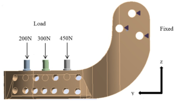
The total average chewing load for all muscles is 911.6 N. The maximum anatomical chewing load corresponds to the maximum contractile power of the muscles when they open the jaw. The chewing load is calculated based on the relation between the load developed by a skeletal muscle and the muscular cross unit area. In [27], authors reported that chewing load is between 210 to 400 kg (2060.1 to 3924 N). The numerical analysis presented in this work considered diverse parameters such as average maximum loads (i.e. that the load is uniformly distributed along the chewing line) and applied elastic, isotropic and homogeneous conditions. The numerical simulation was performed in a 3D model, with high order elements with 20 nodes. Figure 5 shows applied boundary conditions at the edges of jaw implant, as well as the exerted loads. The used mechanical properties are those for Titanium (ELI) Grade 5 alloy alpha beta with 6% Al and 4% V, Young’s modulus 200 GPa, Poisson relation of 0.28 and a yield strength of 900 MPa [28].
|
| Figure 5: Loading and boundary conditions at the jaw prosthesis. |
Performed simulations required an intensive processing burden (50-60 minutes per simulation). Simulations results show the relation between the applied loads, the geometrical characteristics of material, the restrictions and deformations. von Mises theory to determine stress was used, in order to determine the stress distribution along the prosthesis.
4 Results
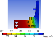
Two study cases were analysed: a mandible himiprosthesis featuring screws to place teeth, and a second one without such screws. Developed von Misses stress and equivalent strain during the chewing cycle, i.e. with an applied average load of 911.6, were calculated. Figure 6 show total displacement, von Misses stress and equivalent strain of the implant when undergoing a maximum load of 3924 N. With the previously mentioned load conditions, the numerical simulations obtained for both cases show the minimum and maximum stresses for the first right third of the mandible branch, where the anchorage with the mandibular bone is not considered. As it can be observed from Figure F7b, the obtained stresses does not exceed the yield strength of the material (900 MPa [28]); clearly, the found values are below the yield strength of material, independently of the irregularities int he carpo zone and the mandibular branch. It also ought to be noted that the stress distribution is practically symmetric in the low and up parts of the maxillary angle.
|
|
|
| (a) Total displacement. | (b) von Misses stress. | (c) Strain. |
| Figure 6: Maximum loading FEM results. | ||
The half-lower jaw prosthesis, showed in Figure 4, was manufactured with a bio-compatible material (Titanium ELI) using only one piece and applying compression forces during the manufacturing process. The implant was modelled to provide a similar morphological pattern, which allow the optimal replacement of the mandibular resected bone. The endo-prosthesis has a series of holes to decrease prosthesis weight, without decreasing its structural integrity. One of its ends has the form of the mandibular notch and neck, allowing its connection to the condyle through an anchorage, that holds the condyle to the upper jaw. It is possible to apply this kind of attachment because the jaw angle depends on the morphological characteristics of the patient. Both ends of the prosthesis are screwed to the patient with surgical bolts, as it is shown in the Figure 7.

|
| Figure 7: New half lower jaw prosthesis attache into the model. |
Results from the numerical simulation show that von Misses stresses, strains and total displacements are low when an average chewing load is applied. These are under the mechanical risk zone that Titanium could undertake, so the implant should work properly under normal chewing conditions. If the chewing load reaches a maximum value, the implant should work just under its mechanical yield zone; so if the patient is exposed to this condition it would not reach a critical value. Nevertheless, several physiological and physical factors would not permit to reach the maximum load.
5 Discussion
In this work, a personalised half lower jaw prosthesis using X-Ray tomography and a fused deposition modelling technique, was developed. The prosthesis was successfully implanted in Mexico, to a patient suffering jaw bone cancer, as it is shown in Figure 8. The surgery procedure, performed to the patient, was to partially amputate the mandibular bone. The innovation presented in this work, is the application of 3D technology (modelling) to reconstruct half of the lower mandibular bone by inserting an endo-prosthesis.
As mentioned by [29], computer-assisted procedures have proven to be effective methods to obtain dental alignment between the upper and lower jaw. Nevertheless, as in this work the developed prosthesis was customised, it naturally provides a correct alignment with the face structure and with the healthy mandibular bone. Additionally, prosthetic teeth can be attached to tolerate normal chewing. Also, the customisation of the prosthesis should allow a better life quality to the patient. The development of this prosthesis can be used to tackle three different mandibular bone deficiencies: as an artificial condyle, as a band for the substitution of the principal jaw bone and as a strip band for an additional fixation member.
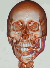
|
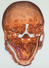
|
| (a) Frontal plane. | (b) Cross plane. |
| Figure 8: Jaw surgery. | |
As for the surgical recovery period, the first stage, once after the patient has recovered from surgical medic process (organ stabilisation), consists on evaluating and attending the functional and aesthetic consequences of the procedure. In the case of the lower jaw loss, the immediate consequences are related to the respiratory, the digestive and the vocal systems, as well as to the evolution of organ reactions depending on sleeping. The prosthesis restitution implies, first of all, the recovery of organ systems and basic functions, from the medical point of view. From the patient's point of view, it is important to restore a natural aesthetic appearance, which could bring confidence to the person. Within this first stage, there is a consensual solution for both parts (medical and patient): the prosthetic implant must adjust to the biological appearance and perform the required functions. The new low jaw prosthesis developed in this paper, is aimed to provide both functions.
In the second stage of recovery, the manufactured prosthesis should be refined and detailed for the customisation for the patient and his requirements [30]. Although in most cases, health carers perform three-dimensional soft tissue modelling of chin, for implementing an aesthetics treatment, in this case the prosthetic implant has already been personalised to suit morphological aspects of the patient. So it is expected that the prosthesis integration occurs in a natural manner to the respiratory and digestive biological processes. Additionally, it should not hinder its integration to adjacent organs (tongue, teeth, trachea, chew, etc.). Within the aesthetic aspect, the general integration should arise in patient's mind. The total recovery after surgery should provide confidence to the patient and his face should match or be very similar to the one before surgery, conserving his face symmetry, without cosmetics factors, and his functions should work properly.
In a third and last recovery stage, the application and normal service (rehabilitation) of the prosthesis was assessed. Prosthesis should be analysed and corrected, in case of any collateral effects, organ adjustments (life of the prosthesis), as well as not working properly, inherently. Cosmetic variations must be determined (ageing in comparison to prosthetic), which could require adjustment interventions. These should be easy, due to the prosthesis design herein developed.
6 Conclusion
This research deals with a system of metal mandibular prosthesis for patients who have undergone a subtotal resection hemimandibulectomy. This prosthesis was developed in order to restore damaged functions when the lower part of the jaw was injured by tumour cancer. The presented metal mandibular prosthesis provides consolidation, hygiene and easiness in bone implant, which is able of respond to a partial resection without affecting the jaw or temporomandibular joint condyle, the replacement of teeth. The prosthesis have three mobility axes: X, Y and Z rotatory capacity, simulating natural bite. It also provides aesthetic volume and it gives volume and tone to facial muscles in order to provide an adaptation to any patient's morphological geometry. Although designed for humans, the procedure herein developed to design and manufacture jaw prosthesis could be easily extended for its usage in veterinary area.
Acknowledgements:
The authors gratefully acknowledge the financial support from the Mexican government by Consejo Nacional de Ciencia y Tecnología, to the Instituto Politécnico Nacional and the biomechanics group of INSIA from the Universidad Politécnica of Madrid. Authors also acknowledge partial support projects 20181139, 20180472, 20181441, 20181028, 20181141, 20195634, 20195343, 20190136, 20196710, and 1930, as well as EDI grant, all provided by SIP/IPN.
Conflict of Interest
The authors declare that there is no conflict of interest regarding the publication of this paper. The founding sponsors had no role in the design of the study; in the collection, analyses, or interpretation of data; in the writing of the manuscript, and in the decision to publish the results.
BIBLIOGRAPHY
[1] Guarda-Nardini, L and Manfredini, D and Ferronato, G. (2008) "Temporomandibular joint total replacement prosthesis: current knowledge and considerations for the future", Volume 37. Elsevier. International journal of oral and maxillofacial surgery 2 103–110
[2] Madsen, Matthew J and Haug, Richard H. (2006) "A biomechanical comparison of 2 techniques for reconstructing atrophic edentulous mandible fractures", Volume 64. Elsevier. Journal of oral and maxillofacial surgery 3 457–465
[3] Tideman, H and Samman, N and Cheung, LK. (1998) "Functional reconstruction of the mandible: a modified titanium mesh system", Volume 27. Elsevier. International journal of oral and maxillofacial surgery 5 339–345
[4] Maki, K and Miller, AJ and Okano, T and Shibasaki, Y. (2001) "A three-dimensional, quantitative computed tomographic study of changes in distribution of bone mineralization in the developing human mandible", Volume 46. Elsevier. Archives of Oral biology 7 667–678
[5] Torreira, Mercedes GALLAS and Fernandez, Jose Ramon. (2004) "A three-dimensional computer model of the human mandible in two simulated standard trauma situations", Volume 32. Elsevier. Journal of Cranio-Maxillofacial Surgery 5 303–307
[6] Seper, László and Piffkó, József and Joos, Ulrich and Meyer, Ulrich. (2004) "Treatment of fractures of the atrophic mandible in the elderly", Volume 52. Wiley Online Library. Journal of the American Geriatrics Society 9 1583–1584
[7] Nagasao, Tomohisa and Miyamoto, Junpei and Tamaki, Tamotsu and Kawana, Hiromasa. (2010) "A comparison of stresses in implantation for grafted and plate-and-screw mandible reconstruction", Volume 109. Elsevier. Oral Surgery, Oral Medicine, Oral Pathology, Oral Radiology, and Endodontology 3 346–356
[8] Bak, Mathew and Jacobson, Adam S and Buchbinder, Daniel and Urken, Mark L. (2010) "Contemporary reconstruction of the mandible", Volume 46. Elsevier. Oral oncology 2 71–76
[9] Katsuragi, Yoko and Kayano, Shuji and Akazawa, Satoshi and Nagamatsu, Shogo and Koizumi, Takuya and Matsui, Takahiro and Onitsuka, Tetsuro and Yurikusa, Takashi and Huang, Wei-Chao and Nakagawa, Masahiro. (2011) "Mandible reconstruction using the calcium-sulphate three-dimensional model and rubber stick: a new method,‘mould technique’, for more accurate, efficient and simplified fabrication", Volume 64. Elsevier. Journal of Plastic, Reconstructive & Aesthetic Surgery 5 614–622
[10] Clason, Christian and Hinz, Andreas M and Schieferstein, Heinrich. (2004) "A method for material parameter determination for the human mandible based on simulation and experiment", Volume 7. Taylor & Francis. Computer methods in biomechanics and biomedical engineering 5 265–276
[11] Del Palomar, A Perez and Doblaré, M. (2006) "Finite element analysis of the temporomandibular joint during lateral excursions of the mandible", Volume 39. Elsevier. Journal of Biomechanics 12 2153–2163
[12] Simon, ENM and Merkx, MAW and Shubi, FM and Kalyanyama, BM and Stoelinga, PJW. (2006) "Reconstruction of the mandible after ablative surgery for the treatment of aggressive, benign odontogenic tumours in Tanzania: a preliminary study", Volume 35. Elsevier. International journal of oral and maxillofacial surgery 5 421–426
[13] Liao, Sheng-Hui and Tong, Ruo-Feng and Dong, Jin-Xiang. (2007) "Anisotropic finite element modeling for patient-specific mandible", Volume 88. Elsevier. Computer methods and programs in biomedicine 3 197–209
[14] Buchaillard, Stéphanie and Brix, Muriel and Perrier, Pascal and Payan, Yohan. (2007) "Simulations of the consequences of tongue surgery on tongue mobility: implications for speech production in post-surgery conditions", Volume 3. Wiley Online Library. The International Journal of Medical Robotics and Computer Assisted Surgery 3 252–261
[15] Manolidis, Spiros. (2000) "Modular mandibular prosthesis". Google Patents
[16] Gordon, Jeffrey D. (1996) "Apparatus for total temporomandibular joint replacement". Google Patents
[17] Nealis, Michael F. (1995) "Temporomandibular joint prosthesis". Google Patents
[18] Collins, Thomas A. (1988) "Mandibular prosthesis". Google Patents
[19] Touleimat, Saad and Touleimat, Abdul-Elah. (2014) "Adjustable mandible joint system". Google Patents
[20] Van Loon, Jan-paul. (1999) "Adjustable temporomandibular surgical implant". Google Patents
[21] Camardella, Leonardo Tavares and Vilella, Oswaldo V and van Hezel, Marleen M and Breuning, Karel H. (2017) "Accuracy of stereolithographically printed digital models compared to plaster models". Springer. Journal of Orofacial Orthopedics/Fortschritte der Kieferorthopädie 1–9
[22] Pruim, GJ and De Jongh, HJ and Ten Bosch, JJ. (1980) "Forces acting on the mandible during bilateral static bite at different bite force levels", Volume 13. Elsevier. Journal of biomechanics 9 755–763
[23] Weijs, WA and Hillen, B. (1984) "Relationship between the physiological cross-section of the human jaw muscles and their cross-sectional area in computer tomograms", Volume 118. Karger Publishers. Cells Tissues Organs 3 129–138
[24] J.W.C. MacDonald and A.G. Hannam. (1984) "Relationship between occlusal contacts and jaw-closing muscle activity during tooth clenching: Part I", Volume 52. The Journal of Prosthetic Dentistry 5 718 - 729
[25] J.W.C. MacDonald and A.G. Hannam. (1984) "Relationship between occlusal contacts and jaw-closing muscle activity during tooth clenching: Part II", Volume 52. The Journal of Prosthetic Dentistry 6 862 - 867
[26] E. Moller. (1996) "The chewing apparatus; An electomyographic study of the action of the muscles of mastication and its correlation to facial morphology", Volume 280. Acta Physiological Scandinavian Supplement 1-229
[27] G. Nelson. (1986) "Three dimensional Computer modeling of human mandibular biomechanics". The university of British Columbia 201-226
[28] Lütjering, G and Williams, JC and Gysler, A. (2000) "MICROSTRUCTURE AND MECHANICAL PROPERTIES OF TITANIUM ALLOYS". Microstructure And Properties Of Materials: (Volume 2). World Scientific 1-77
[29] Zizelmann, C and Bucher, P and Rohner, D and Gellrich, N-C and Kokemueller, H and Hammer, B. (2010) "Virtual restoration of anatomic jaw relationship to obtain a precise 3D model for total joint prosthesis construction for treatment of TMJ ankylosis with open bite", Volume 39. Elsevier. International journal of oral and maxillofacial surgery 10 1012–1015
[30] Holberg, Christof and Heine, Anne-Kathrin and Geis, Philipp and Schwenzer, Katja and Rudzki-Janson, Ingrid. (2005) "Three-dimensional soft tissue prediction using finite elements", Volume 66. Springer. Journal of Orofacial Orthopedics/Fortschritte der Kieferorthopädie 2 122–134
Document information
Published on 04/03/19
Accepted on 25/02/19
Submitted on 13/02/18
Volume 35, Issue 1, 2019
DOI: 10.23967/j.rimni.2019.02.001
Licence: CC BY-NC-SA license