m (Jsogorb moved page Draft Sogorb 929124143 to Review 400440468313) |
|||
| Line 123: | Line 123: | ||
===2.3. Light optical microscopy=== | ===2.3. Light optical microscopy=== | ||
| − | Light Optical Microscopy characterization was conducted on an Olympus BX41RF-LED microscope. The samples were cut in transverse direction and cold mounted in | + | Light Optical Microscopy characterization was conducted on an Olympus BX41RF-LED microscope. The samples were cut in transverse direction and cold mounted in methyl-methacrylate resin KEM 35 (QATM®). The sections of interest were grounded by using 120, 400, 1200 and 2500 grit SiC paper and polished with 0.06 μm alumina suspension Eposal (QATM®). Optical observations of the fracture surfaces were performed through a digital microscope HRX-01 (Hirox). |
===2.4. Mechanical characterization=== | ===2.4. Mechanical characterization=== | ||
Revision as of 10:03, 23 May 2023
1. Introduction
Over the last decades, there has been a progressive increase in the use of composite materials in many sectors such as aerospace, automotive or marine, due to notable weight savings, specific strength, and corrosion resistance. Thermoplastic matrix-based composites (TMC) are gaining interest over the thermoset matrix-based due to diverse mechanical and processing advantages [1, 2]. One of the most interesting aspects of the TMC is the possibility of reprocessing after consolidation due the chemical properties of the high-performance thermoplastic matrix systems such as PEEK, PEKK or PPS. This characteristic allows TMC being re-shaped, welded and recycled [3, 4]. Composites welding processes result an interesting alternative to overcome the drawbacks related to the conventional mechanical fastening such as stress concentrations, damage of reinforcing fiber by drilling, mismatch of coefficient of thermal expansion, and heavier structures. Adhesive bonding of TMC also presents difficulties due to the lack of compatibility between the thermoplastic resins and the adhesives, requiring an extensive surface preparation. The existing welding technologies for assembling TMC structures can be classified into three categories depending on how heat is generated at the interface: electromagnetic welding, thermal welding, and friction welding [5, 6, 7]. Several investigations have been made in this field (i.e. ultrasonic welding [7, 8], resistance welding [9], and induction welding -IW- [10]). However, future research into thermoplastic welding processes is needed to assemble large and complex shapes structures, increase manufacturing rates, and decrease structures weight.
The purpose of this research is to characterize the induction welded joint produced between a short carbon fiber reinforced polyether ether ketone (SCFR/PEEK) part processed by additive manufacturing (AM) technology – fused deposition modeling (FDM), and a carbon fiber reinforced PEEK (CFR/PEEK) laminate consolidated in an oven. Localized heat is generated because of the induced eddy currents in the carbon fiber reinforcement through the application of an alternating electromagnetic field [5]. Optical microscopy was used to examine the welded interface for possible indications of thermal degradation of the resins, damage within the adherends, or the continuity between them throughout the weld. Infrared thermography (IRT) was evaluated as a non destructive technique (NDT) for induction welded structures evaluation. IRT is a flexible, fast and easy to automate NDT that will allow the validation of future complex and highly integrated components. IRT results were validated by x-Ray computed tomography (XCT) technique. Block shear test was selected to evaluate the mechanical strength of the inductively welded joints, due to the large differences between the mechanical properties of the welded parts (produced by different manufacturing technologies). However, the widely used single-lap shear tensile requires increasing the thickness of the adherend with less mechanical resistance, which would introduce an eccentricity in the load path, promoting bending and normal forces (peeling forces). These peel forces can cause a failure within the substrate rather than characterize the strength of the weld [11].
2. Materials and Methods
2.1. Materials and samples preparation
In this study two different carbon fiber reinforced polyether ether ketone materials were used (both developed by Solvay):
- 1. Carbon fiber reinforced Ketaspire® CF10 LS1 AM filament (KT-CF10) with a diameter of 1.75 mm. The KT-CF10 consists of a short carbon fiber reinforced PEEK matrix with a carbon content of 10% in weight and a density of 1.33 g/cm3. KT-CF10 has a melting temperature of 343 °C and a processing temperature range of 390-420 °C.
- 2. Unidirectional carbon fiber thermoplastic prepreg APC-2 PEEK/AS4 12k with a fiber areal weight of 145 g/m2, a resin content of 34% in weight and a glass transition temperature of 143 °C. The fiber and resin density are 1.79 and 1.32 g/cm3, respectively.
The KT-CF10 was processed with a GEWO HTP260. This FDM system enables the processing of high-performance polymers due to the actively heated build chamber of up 260 °C. For the processing of KT-CF10, a nozzle temperature of 450 °C and a chamber temperature of 260 °C were used. In Table 1 are included the main process parameters used for KT-CF10.
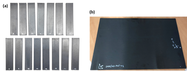
A series of rectangular samples (Figure 1a) of 135 x 30 x 4.58 mm were printed with 100% infill and ±45° orientation.
| Nozzle diameter
[mm] |
Layer height
[mm] |
Nozzle temp.
[°C] |
Chamber temp.
[°C] |
Bed temp.
[°C] |
| 0.6 | 0.375 | 450 | 260 | 260 |
The consolidation cycle of the APC-2 PEEK/AS4 prepreg was conducted in an oven at 400°C (±5°C) for 15-20 minutes with a vacuum level of 0.7-0.8 bar. A CFR/PEEK laminate of 700 x 450 mm and a nominal thickness of 2.43 mm was manufactured (Figure 1b) with stacking sequence [0/+45/-45/0/-45/+45/90/-45/+45]s.
2.2. Induction welding process
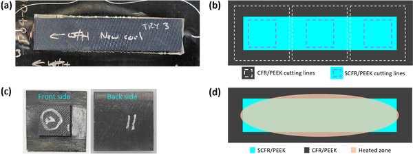
The individual SCFR/PEEK samples manufactured by FDM were inductively welded to the thermoplastic CFRP/PEEK laminate in a single-sided joint configuration with a PEEK film of 0.5 mm placed between both adherends (Figure 2a). The welding system (Figure 2b) was specifically designed for this configuration and material characteristics. The welding parameters are listed in Table 2, allowing a maximum temperature of 363 °C.
| Pressure
[MPa] |
Frequency
[kHz] |
Current
[A] |
Time
[sec] |
Welding zone/Coil distance
[mm] |
| 0.5 | 250 | 290 | 100 | 4.58 |
The final SCFR/PEEK sample welded to the CFRP/PEEK laminate is shown in Figure 3a. Block shear specimens were obtained by machining the SCFR/PEEK part and the CFRP/PEEK laminate as indicated in Figure 3b, resulting in three specimens per welded part. The sample geometry (Figure 3c) was defined based on the ASTM D4501 standard, consisting of a 25 x 25 mm SCFR/PEEK part welded to a CFR/PEEK plate of 50 x 50 mm.
During the welding process, the distribution of the induced heat presents an elliptical geometry as indicated in Figure 3d, so that the heat only covers the full test area of the specimen extracted from the central zone of the assembly while process is only partial at the extremes.
2.3. Light optical microscopy
Light Optical Microscopy characterization was conducted on an Olympus BX41RF-LED microscope. The samples were cut in transverse direction and cold mounted in methyl-methacrylate resin KEM 35 (QATM®). The sections of interest were grounded by using 120, 400, 1200 and 2500 grit SiC paper and polished with 0.06 μm alumina suspension Eposal (QATM®). Optical observations of the fracture surfaces were performed through a digital microscope HRX-01 (Hirox).
2.4. Mechanical characterization
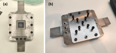
The strength of the induction welded joints was evaluated by the block shear test in accordance with the ASTM D4501 standard. The tests were conducted on the universal testing machine Zwick/Roell Z100 at 1.26 mm/min crosshead speed and room temperature conditions. A modification of the common block shear fixture was made so it can be adapted to each specimen depending on the degree of curvature and dimensions (Figure 4) since the IW process produced small shape distortions.
The block shear strength (BSS) was calculated from the measured maximum tensile load F through equation (1), where l and w are the length and width of the weld, respectively, measured after the sample failure.
|
|
(1) |
2.5. Non-destructive inspection
IRT inspections were performed with an infrared camera (FLIR SC7000) with a resolution of 640 x 512 px that operates at a bandwidth of 3 - 5 µm. The camera uses an Indium Antimonide (InSb) detector and a 25 mm F/2 (22˚ x 17˚) lens. To provide the thermal excitation two halogen lamps (Hedler H25s) with a power of 2kW were used. IRT inspection parameters are listed in Table 3. Specimens were inspected in reflection mode through the CFR/PEEK laminate side.
| Inspection time
[sec] |
Excitation time
[sec] |
Power
[kW] |
Sample/IR-camera distance
[mm] |
Sample/lamps distance
[mm] |
| 60 | 6 | 4 | 390 | 450 |
The IRT results were validated by means of XCT with a VJT 225 µ-CT equipment (225kV and 3 mA X-ray unit; 2048 x 2048 px detector).
3. Results and Discussion
3.1. Light optical microscopy characterization of induction welded samples
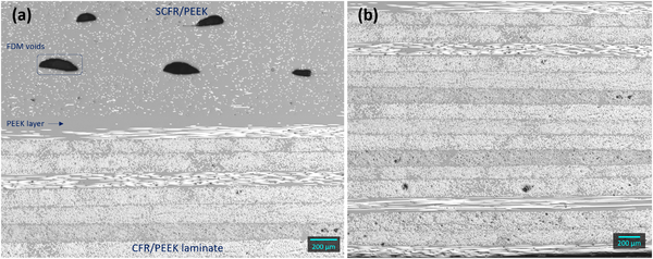
The micrographs conducted on the cross-section of the studied welded joints revealed a good continuity between both adherends throughout the entire weld interface (Figure 5a). The SCFR/PEEK part and the CFR/PEEK laminate, separated by a PEEK-rich layer of approximately 92 μm, can be clearly distinguished. The SCFR/PEEK part presents the typical voids related to the discrete addition of material in the FDM process [12]. The use of a PEEK film of 0.5 mm between both adherends helped to homogenize the welded interface by compensating the lack of material within the first printed layer of the SCFR/PEEK part. Optical micrographs did not reveal visible signs of thermal degradation of the resins (i.e. porosity) and no damage was observed in the CFR/PEEK laminate after the welding process (Figure 5b).
3.2. Non-destructive inspection of induction welded samples
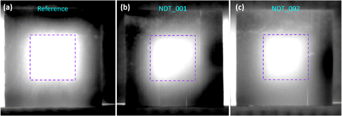
The IRT analysis was performed on the samples extracted from the central area of the joint (fully welded, considered as the reference) and the extremes NDT_001 and NDT_002 (partially welded because of the welding process configuration). Infrared thermal image sequences were processed by using the pulsed phase thermography (PPT) method to obtain the phase contrast gray-scale images (Figure 6), where a square (region of interest, ROI) was marked with the size of the theoretically welded area (TWA). In the case of the reference specimen, size and shape of the indication reported by the phase contrast image is in agreement with the TWA, while the indications obtained from NDT_001 and NDT_002 show a lack of contrast around the edges and the lower right corner of the TWA.
The quantification analysis is based on the radiation index (understood as brightness level in the grey scale of the thermogram). The calculus has been made towards the average gray intensity of the ROI. The average gray levels within the TWA are: 253.3 (reference), 236.1 (NDT_001), and 239.9 (NDT_002). A reduction of around 6.8 and 5.3% can be observed with respect to the reference value for NDT_001 and NDT_002, respectively, due to the presence of non-welded areas.
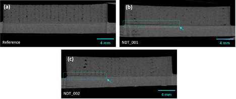
The previous results were validated by means of computed tomography (XCT). XCT allows a 3D reconstruction of the welded interface that where it is possible the identification of non-welded areas. XCT observations confirmed the correlation between the lack of contrast within the TWA of the IRT phase contrast images and the non-welded areas. The cross-section of the reference sample (Figure 7a) obtained by XCT reported a complete weld throughout the sample, which means that the indication detected by IRT (Figure 6a) corresponds to a fully welded interface. The cross-sections of NDT_001 (Figure 7b) and NDT_002 (Figure 7c) revealed a discontinuity between both adherends corresponding to a non-welded area (marked by a square), consistent with the lack of contrast detected in the lower right corner of the TWA by IRT in both cases (Figure 6b and Figure 6c, respectively).
3.3. Mechanical resistance of induction welded samples
The results of the block shear tests corresponding to the specimens extracted only from the central zone of the assembly are listed in Table 4. Average BSS of 23.3 MPa was obtained with a standard deviation of 1.4 MPa.
| ID sample | BSS [MPa] |
| BS_001 | 23.2 |
| BS_002 | 21.2 |
| BS_003 | 24.8 |
| BS_004 | 22.2 |
| BS_005 | 24.0 |
| BS_006 | 24.5 |
| Average ± Std. dev. | 23.3 ± 1.4 |
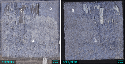
Figure 8 shows a representative fracture surface of the welded specimens after the block shear test. A cohesive failure (Figure 8 (a)) occurred within the weld interface, involving the adjacent areas of the PEEK layer and the SCFR/PEEK substrate, resulting in the major failure mechanism of welded joints. It can be identified by the grainy appearance on both sides of the fracture. An interlayer failure also occurred within the SCFR/PEEK substrate on a smaller surface (Figure 8 (b)) indicating that the interface resistance was higher than the substrate. Adhesive failure was observed in the remaining areas (Figure 8 (c)) where the PEEK layer with a few fibers adhered was removed from the CFR/PEEK laminate due to insufficient adhesion.
Considering the main failure mechanism (cohesive), the block shear test was proved a good option to evaluate the mechanical strength of welded joints between adherends with large differences in their mechanical behaviour, avoiding the introduction of peel stresses that are responsible for the delamination in carbon fiber reinforced adherends [11].
4. Conclusions
In this investigation, SCFR/PEEK parts processed by AM-FDM technology were inductively welded to a CFR/PEEK laminate consolidated in an oven by charging an electric current of 290 A and a frequency of 250 kHz into the induction coil while applying a pressure of 0.5 MPa during 100 sec. A maximum temperature of 363 °C was generated at the welded interface. Optical microscopy and non-destructive characterization revealed a good continuity between both adherends in the areas of influence of eddy currents and no thermal degradation of the resins or damage to the adherends was observed.
Active IRT technique was considered as a non-contact methodology for the inspection of induction welded joints to evaluate the manufacturing quality. The results confirmed the feasibility of this technique to identify the welded and non-welded areas through the application of PPT processing algorithm to the infrared sequences. The results were validated by means of the 3D reconstruction of the welded interface obtained by XCT.
Finally, the block shear test method presented in this work has resulted in an appropriate alternative to the single lap shear test for the characterization of the mechanical strength of induction welded joints between adherends with large differences in their mechanical behavior, avoiding the eccentricity in the load path that causes bending and peeling forces in the weld zone. An average BSS of 23.3 MPa was obtained with a cohesive failure mechanism.
5. Acknowledgements
This research was funded by the European commission, under the Horizon 2020 research and innovation program, in the framework of the RIB-AM project, grant agreement No. 821233.
References
| [1] | S. Pantelakis and K. Tserpes, Revolutionizing Aircraft Materials and Processes, Springer, 2020. DOI: https://doi.org/10.1007/978-3-030-35346-9. |
| [2] | S. Sajan and D. Philip Selvaraj, "A review on polymer matrix composite materials and their applications," Materials Today: Proceedings 47, 5493–5498, 2021. DOI: https://doi.org/10.1016/j.matpr.2021.08.034. |
| [3] | R. Bernatas, S. Dagreou, A. Despax-Ferreres and A. Barasinski, "Recycling of fiber reinforced composites with a focus on thermoplastic composites," Cleaner Engineering and Technology, 5, 100272, 2021. DOI: https://doi.org/10.1016/j.clet.2021.100272. |
| [4] | I. Y. Chang and J. K. Lees, "Recent Development in Thermoplastic Composites: A Review of Matrix Systems and Processing Methods," Thermoplastic Composite Materials, Vol. 1, Issue 3, 1988. DOI: https://doi.org/10.1177/089270578800100305. |
| [5] | A. Yousefpour, M. Hojjati and J.-P. Immarigeon, "Fusion Bonding/Welding of Thermoplastic Composites," Thermoplastic Composite Materials, Vol. 17, 2004. DOI: https://doi.org/10.1177/0892705704045187. |
| [6] | T. Ahmed, D. Stavrov, H. Bersee and A. Beukers, "Induction welding of thermoplastic composites—an overview," Composites: Part A 37, 1638–1651, 2006. DOI: https://doi.org/10.1016/j.compositesa.2005.10.009. |
| [7] | M. Bonmatin, F. Chabert, G. Bernhart, T. Cutard and T. Djilali, "Ultrasonic welding of CF/PEEK composites: Influence of welding parameters on interfacial temperature profiles and mechanical properties," Composites: Part A 162, 107074, 2022. DOI: https://doi.org/10.1016/j.compositesa.2022.107074. |
| [8] | W. Tao, X. Su, H. Wang, Z. Zhang, H. Li and J. Chen, "Influence mechanism of welding time and energy director to the thermoplastic composite joints by ultrasonic welding," Journal of Manufacturing Processes, 37, 196-202, 2019. DOI: https://doi.org/10.1016/j.jmapro.2018.11.002. |
| [9] | X. Li, T. Zhang, S. Li, H. Liu, Y. Zhao and K. Wang, "The effect of cooling rate on resistance-welded CF/PEEK joints," Journal of Materials Research and Technology, 12, 53-62, 2021. DOI: https://doi.org/10.1016/j.jmrt.2021.02.071. |
| [10] | A. Korycki, C. Garnier, M. Bonmatin, E. Laurent and F. Chabert, "Assembling of Carbon Fibre/PEEK Composites: Comparison of Ultrasonic, Induction, and Transmission Laser Welding," Materials, 15, 6365, 2022. DOI: https://doi.org/10.3390/ma15186365. |
| [11] | A. Redmann, V. Damodaran, F. Tischer, P. Prabhakar and T. A. Osswald, "Evaluation of Single-Lap and Block Shear Test Methods in Adhesively Bonded Composite Joints," J. Compos. Sci, 5, 27, 2021. DOI: https://doi.org/10.3390/jcs5010027. |
| [12] | A. Hernandez-Contreras, L. Ruiz-Huerta, A. Caballero-Ruiz, V. Moock and H. R. Siller, "Extended CT Void Analysis in FDM Additive," Materials, 13, 3831, 2020. DOI: https://doi.org/10.3390/ma13173831. |
Document information
Published on 26/01/24
Accepted on 16/10/23
Submitted on 18/05/23
Volume 08 - COMUNICACIONES MATCOMP21 (2022) Y MATCOMP23 (2023), Issue Núm. 3 - Caracterización - Daño, Fractura y Fatiga, 2024
DOI: 10.23967/r.matcomp.2024.03.04
Licence: Other
Share this document
Keywords
claim authorship
Are you one of the authors of this document?
