(Tag: Visual edit) |
|||
| Line 98: | Line 98: | ||
==Implicit Fractional Step Formulation== | ==Implicit Fractional Step Formulation== | ||
| − | Let us discretize in time the stabilized momentum equation (1a) using the trapezoidal | + | Let us discretize in time the stabilized momentum equation (1a) using the trapezoidal rule (or ''θ'' method) as |
| − | + | {| class="formulaSCP" style="width: 100%; text-align: left;" | |
| − | + | |- | |
| − | + | | | |
| − | + | {| style="text-align: left; margin:auto;width: 100%" | |
| − | + | |- | |
| − | (3) | + | | style="text-align: center;" | <math>\frac{u_i^{n+1}-u_i^n}{\delta t}+\frac{\partial }{\partial x_j}\left(u_i^{n+\theta }u_j^{n+\theta }\right)+</math><math>\frac{\partial p^{n+\theta }}{\partial x_i}-\frac{\partial {\tau }_{ij}^{n+\theta }}{\partial x_j}-</math><math>\frac{1}{2}h_j\frac{\partial r_{m_i}^{n+\theta }}{\partial x_j}=0</math> |
| + | |} | ||
| + | | style="width: 5px;text-align: right;white-space: nowrap;" | (3) | ||
| + | |} | ||
the superscripts n and ''θ'' refer to the time step and to the trapezoidal rule discretization parameter, respectively. For ''θ'' = 1 the standard backward Euler scheme is obtained, which has a temporal error of 0(t). The value ''θ'' = 0.5 gives the standard Crank Nicholson scheme, which is second order accurate in time 0(t<sup>2</sup>). | the superscripts n and ''θ'' refer to the time step and to the trapezoidal rule discretization parameter, respectively. For ''θ'' = 1 the standard backward Euler scheme is obtained, which has a temporal error of 0(t). The value ''θ'' = 0.5 gives the standard Crank Nicholson scheme, which is second order accurate in time 0(t<sup>2</sup>). | ||
| Line 111: | Line 114: | ||
A classical implicit fractional step method can be simply derived by splitting eq. (3). The resulting continuous problem, omitting the boundary and initial conditions for brevity, is as follows: | A classical implicit fractional step method can be simply derived by splitting eq. (3). The resulting continuous problem, omitting the boundary and initial conditions for brevity, is as follows: | ||
| − | + | {| class="formulaSCP" style="width: 100%; text-align: left;" | |
| − | \frac{{\overline{u}}_i^{n+1}-u_i^n}{\delta t}+\frac{\partial }{\partial x_j}\left({\overline{u}}_i^{n+\theta }{\overline{u}}_j^{n+\theta }\right)+\frac{\partial p^n}{\partial x_i}-\frac{\partial {\overline{\tau }}_{ij}^{n+\theta }}{\partial x_j}-\frac{1}{2}h_j\frac{\partial {\overline{r}}_{m_i}^{n+\theta }}{\partial x_j}=0 | + | |- |
| − | \delta t\frac{{\partial }^2}{\partial x_i\partial x_i}\left(p^{n+1}-p^n\right)=\frac{\partial u_i^\ast }{\partial x_i}+\frac{1}{2}h_j\frac{\partial r_d}{\partial x_j} | + | | |
| − | u_i^{n+1}={\overline{u}}_i-\delta t\frac{\partial }{\partial x_i}\left(p^{n+1}-p^n\right) | + | {| style="text-align: left; margin:auto;width: 100%" |
| − | + | |- | |
| − | + | | style="text-align: center;" | <math>\frac{{\overline{u}}_i^{n+1}-u_i^n}{\delta t}+\frac{\partial }{\partial x_j}\left({\overline{u}}_i^{n+\theta }{\overline{u}}_j^{n+\theta }\right)+\frac{\partial p^n}{\partial x_i}-\frac{\partial {\overline{\tau }}_{ij}^{n+\theta }}{\partial x_j}-\frac{1}{2}h_j\frac{\partial {\overline{r}}_{m_i}^{n+\theta }}{\partial x_j}=0</math> | |
| − | + | |} | |
| − | + | | style="width: 5px;text-align: right;white-space: nowrap;" | (4a) | |
| − | + | |} | |
| − | + | {| class="formulaSCP" style="width: 100%; text-align: left;" | |
| − | ( | + | |- |
| − | + | | | |
| − | + | {| style="text-align: left; margin:auto;width: 100%" | |
| − | + | |- | |
| + | | style="text-align: center;" | <math>\delta t\frac{{\partial }^2}{\partial x_i\partial x_i}\left(p^{n+1}-p^n\right)=\frac{\partial u_i^\ast }{\partial x_i}+\frac{1}{2}h_j\frac{\partial r_d}{\partial x_j}</math> | ||
| + | |} | ||
| + | | style="width: 5px;text-align: right;white-space: nowrap;" | (4b) | ||
| + | |} | ||
| + | {| class="formulaSCP" style="width: 100%; text-align: left;" | ||
| + | |- | ||
| + | | | ||
| + | {| style="text-align: left; margin:auto;width: 100%" | ||
| + | |- | ||
| + | | style="text-align: center;" | <math>u_i^{n+1}={\overline{u}}_i-\delta t\frac{\partial }{\partial x_i}\left(p^{n+1}-p^n\right)</math> | ||
| + | |} | ||
| + | | style="width: 5px;text-align: right;white-space: nowrap;" | (4c) | ||
| + | |} | ||
where the terms denoted by an overbar are those calculated with the intermediate velocity ''ū<sub>i</sub>'', which is introduced to allow the momentum splitting. | where the terms denoted by an overbar are those calculated with the intermediate velocity ''ū<sub>i</sub>'', which is introduced to allow the momentum splitting. | ||
Revision as of 09:08, 28 March 2018
Introduction
The prediction of the resistance and wave pattern, joint to the study of the flow around a ship are of major relevance in naval architecture. The analytical and numerical solutions of this problem has challenged mathematicians and hydrodynamicists for over a century.
In recent years, the advent of advanced numerical schemes for the Navier Stokes (NS) equations and the rapid development of computer hardware has enabled a realistic prediction of this problems.
The troubles in accurately solving this problem are mainly due to the difficulty of solving numerically the incompressible fluid dynamic equations, which include significant non linearities and the obstacles in solving the constraint equation stating that at the free surface boundary the fluid particles remain on that surface which position is in turn unknown.
Among the schemes developed over the last decade for the solution of the incompressible NS equations the fractional step schemes [1,2,3,4] yield highly accurate, pressure-stable [2] results by integrating in an explicit manner the advective terms of the NS equations. However, in most of the cases of interest for the naval architecture [5] the use of these techniques requires tens of thousands of time steps per simulation, rendering the schemes impractical. Most of the artificial compressibility and preconditioned schemes suffer from the same shortcoming.
On the other hand, the monolithic schemes treat, in general, the advective term in an implicit manner, which avoids the mentioned disadvantages. Nevertheless, these methods are very expensive from a computational point of view: the velocity and pressure discrete equations are coupled.
This paper presents advances in recent work of the authors to derive a fractional step scheme based on the stabilized finite element method that allows overcoming the above mentioned problem, resulting in a efficient time accurate scheme.
The starting point is the modified governing differential equations for the incompressible turbulent viscous flow and the free surface condition incorporating the necessary stabilization terms via a finite calculus (FIC) procedure developed by the authors [6,7,8,9]. This technique is based on writting the different balance equations over a domain of finite size and retaining higher order terms. These terms incorporate the ingredients for the necessary stabilization of any transient and steady state numerical solution already at the differential equations level.
The resulting stabilized equations are integrated in space using the standard finite element method, and in time using an implicit and uncoupled second order fractional step method, based on the scheme originally proposed by Soto [10].
FIC formulation
We consider the motion around a body of a viscous incompressible fluid including a free surface. The stabilized finite calculus (FIC) form of the governing differential equations [11] for the three dimensional (3D) problem can be written as
where
In above ui is the velocity along the i-th global reference axis, p is the dynamic pressure, β is the wave elevation and τij are the viscous stress tensor components.
Let ni be the unit outward normal to the boundary Ω and denoting by an overbar prescribed values, the boundary conditions for the stabilized problem are:
for t ∈ (t0,tf). The boundary Γ has been considered split into three sets of disjoint components Γu, Γp and Γτ, the latter being the part where mixed conditions are prescribed.
Vectors gi and si span the space tangent to Γτ. Finally, Γu and Γp are the two disjoint components of Γ where Dirichlet and Neumann boundary conditions for the velocity are prescribed. Initial conditions have to be appended to problem (1)-(2).
The underlined terms in eqs. (1)-(2) introduce the necessary stabilization for the numerical solution. Additional time stabilization terms can be accounted for in eqs. (1)-(2) [6,7] although they have been found unnecessary for the type of problem solved here.
The characteristic length distances hj represent the dimensions of the finite domain where balance of momentum and mass is enforced. The characteristic distances hβj in eq. (1c) represent the dimensions of a finite domain surrounding a point where the velocity is constrained to be tangent to the free surface. Details of the derivation of eqs. (1)-(2) and recommendations for computation of the stabilization parameters can be found in [6,12,13].
Eqs. (1)-(2) are the starting point for deriving a variety of stabilized numerical methods for solving the incompressible Navier-Stokes equations with a free surface. It can be shown that a number of stabilized finite element methods and new meshless methods allowing equal order interpolations for the velocity and pressure fields can be from the modified form of the momentum and mass balance equations given above [6-9].
Implicit Fractional Step Formulation
Let us discretize in time the stabilized momentum equation (1a) using the trapezoidal rule (or θ method) as
|
|
(3) |
the superscripts n and θ refer to the time step and to the trapezoidal rule discretization parameter, respectively. For θ = 1 the standard backward Euler scheme is obtained, which has a temporal error of 0(t). The value θ = 0.5 gives the standard Crank Nicholson scheme, which is second order accurate in time 0(t2).
A classical implicit fractional step method can be simply derived by splitting eq. (3). The resulting continuous problem, omitting the boundary and initial conditions for brevity, is as follows:
|
|
(4a) |
|
|
(4b) |
|
|
(4c) |
where the terms denoted by an overbar are those calculated with the intermediate velocity ūi, which is introduced to allow the momentum splitting.
The error due to taking implicit advective and viscous terms in (4a) can be shown [10] to be of the same order than the error of the stabilizing term and therefore, it has the same order of approximation than the original time discretization (3).
Monolithic Stabilized Scheme
At this point, it is important to introduce the associated matrix structure corresponding to the variational discrete form of (4) (see [6] for details of this derivation):
By taking Ūn+1 from (5c) and inserting the result in (5a)-(5b), the following system of equations is obtained:
The term E(Un+θ) in (6a) is the error coming from the implicit treatment of the advective and viscous terms, which is of order 0(t2). However, such term can be eliminated as in (6a)-(6b) by writing the following analog monolithic scheme:
Basically, in this final formulation the convergence of the block uncoupled solution is enforced by the first term of (7b), while the pressure stability is attained by the second term of the same equation.
Finally, the wave elevation coupling effect is included in the monolithic scheme, obtaining the following system of equations:
where the Uin+θ is the vector of the velocity along the i-th global reference axis.
Figure shows the flow chart of the solution algorithm of eqs. (8).
Application Examples
The algorithm here presented have been implemented within the CFD environment Tdyn [14,15]. This software has been used to solve the examples shown next.
Example 1. DTMB 5415 model
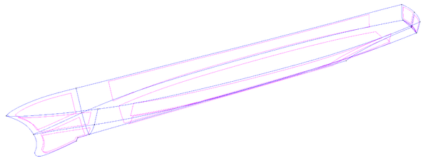
The first case here analysed is a benchmark test case, the David Taylor Model Basin (DTMB) 5415 model. The geometry used in the analysis was obtained from the Gothemburg 2000 Workshop database [16] and is based on the NURBS definition shown in Figure 2.
|
| Figure 2. DTMB 5415. Hull geometry based on the NURBS entities. |
|
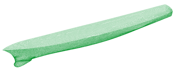
| Figure 3. DTMB 5415. Surface mesh on the hull. |
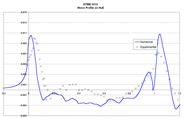
The obtained results are compared with the experimental data available in the EFD database developed by the Iowa Institute of Hydraulic Research, the Instituto Nazionale per Studi ed Esperienze di Architettura Navale and the Naval Surface Warfare Center [16].
|
| Figure 4. DTMB 5415. Wave Profile on hull. |
The main characteristics of this analysis are listed below:
| Length: | 5.72 m | Beam: | 0.5 m |
| Draught: | 0.248 m | Wetted Surface: | 4.861m2 |
| Velocity: | 2.1 m/s | Froude Number: | 0.28 |
| Viscosity: | 0.001 Kg/ms | Density: | 1000 Kg/m3 |
| Reynolds number: | 12.3 106 |
The analysis was carried out for three different grids (from 150.000 to 600.000 linear tetrahedra, corresponding to 25.000 and 115.000 nodes) in order to qualitatively analyse the influence of the element size in the solution. Here, only the results corresponding to the finest grid are shown. The smallest element size used was 0.002 m and the maximum 0.750 m. The surface mesh of the DTMB 5415 used in the last analysis is shown in Figure 3. The Smagorinsky turbulence model with the extended law of the wall was used.
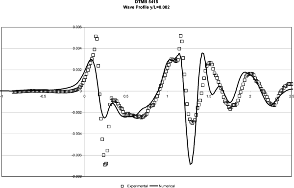
Figures 4 and 5 show the wave profile on the hull and in a cut at y/L =0.082, respectively. Numerical results obtained with the numerical model are compared to the experimental data.
| Figure 5. DTMB 5415. Wave Profile y/L = 0.082. |
Example 2. KVLCC2 Model
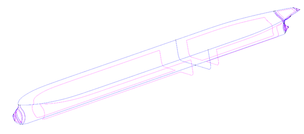
The next example is another benchmark test case, the KVLCC2 model. The geometry used in the example, presented in Figure 6, is based in a NURBS surface definition obtained from the Hydrodynamic Performance Research team of Korea (KRISO) 17. The obtained results are compared with the experimental data available in the KRISO database [19].
|
| Figure 6. KVLCC2. Hull geometry based on the NURBS entities. |
|
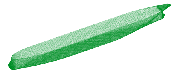
| Figure 7. KVLCC2. Surface mesh on the hull. |
Several simulations of this model were carried out, in order to complete the comparison with the experimental data available. The mesh used in all cases has 380.000 linear tetrahedra elements and 70.000 nodes. The smallest element size used was 0.001 m and the maximum was 0.50 m. The surface mesh of the KVLCC2 used is shown in Figure 7.
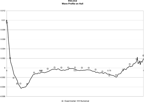
| Figure 8. KVLCC2. Wave Profile on hull. |
Test 1.- Wave pattern calculation. The main characteristics of this analysis are listed below:
| Length: | 5.52 m | Beam: | 0.82 m |
| Draught: | 0.18 m | Wetted Surface: | 8.08 m2 |
| Velocity: | 1.05 m/s | Froude Number: | 0.142 |
| Viscosity: | 0.00126 Kg/ms | Density: | 1000 Kg/m3 |
| Reynolds number: | 4.63 106 |
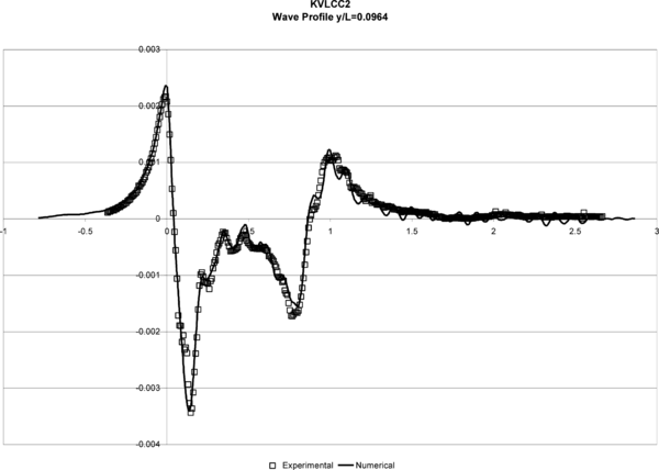
The turbulence model used in this case was the K model. Figures 8 and 9 show the wave profiles on the hull and in a cut at y/L = 0.082 obtained in test 1, compared to the experimental data. The obtained results are quantitatively good close to the hull, but a lost of accuracy can be observed in the profiles further from the hull. This is probably due to the fact that the element sizes are not small enough in this area, for an accurate enough capture of the fluid perturbation.
| Figure 9. KVLCC2. Wave Profile y/L = 0.0964. |
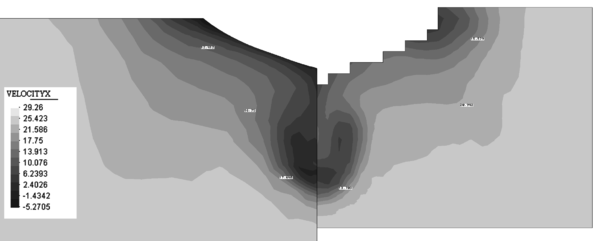
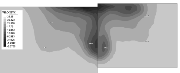
Test 2.- Wake analysis at different planes. Several turbulence models were used in this phase (Smagorinsky, K and K − ε model) in order to verify the quality of the results. Here, only the results corresponding to the last case are shown. However, it is important to note that the velocity maps obtained even for the simplest Smagorinsky model were qualitatively good, showing the accuracy of the fluid flow solver scheme used.
|
| Figure 10. Contours of the X component of the velocity on a plane at 2.71 m from the aft perpendicular. Comparison with experimental data (right). |
|
| Figure 11. Contours of the X component of the velocity on a plane at 2.82 m from the aft perpendicular. Comparison with experimental data (right). |
The main characteristics of this analysis are listed below:
| Length: | 2.76 m | Beam: | 0.41 m |
| Draught: | 0.09 m | Wetted Surface: | 2.02 m2 |
| Velocity: | 25 m/s | Froude Number: | 0.0 |
| Viscosity: | 3.05 10-5 Kg/ms | Density: | 1.01 Kg/m3 |
| Reynolds number: | 4.63 106 |
Figure 10 shows the contours of the X component of the velocity on a plane at 2.71 m from the aft perpendicular compared with the experimental data available.
Figure 11 shows the map of the X component of the velocity on a plane at 2.82 m from the aft perpendicular compared with the experimental data available.
Example 3. 79’ Catamaran
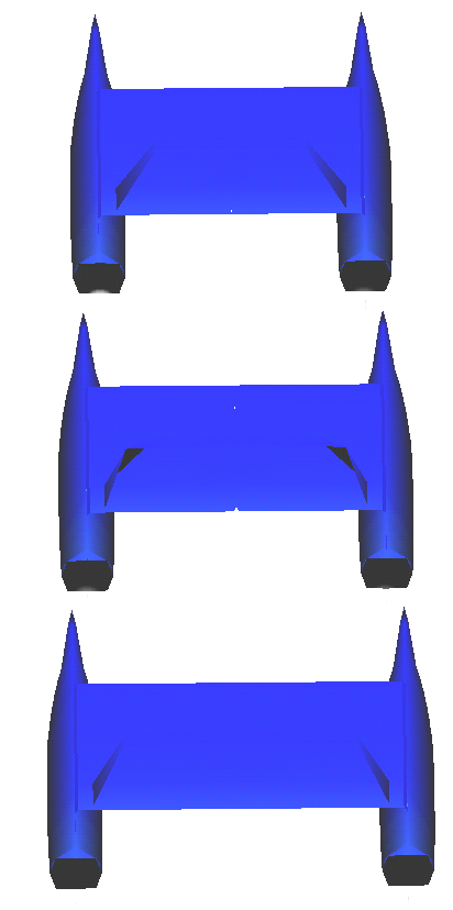
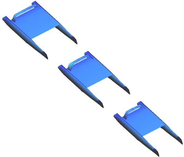
The application example here presented is the parametric analysis of a 79´ catamaran designed by the company NAUTATEC. The main characteristics of this boat are listed next (see Figure 12):
| Length overall | 23.95 m |
| Length between perpendiculars | 23.35 m |
| Total breadth | 11.75 m |
| Extreme breadth of every hull | 1.65 m |
| Draught with appendages | 1.31 m |
| Hull depth | 2.40 m |
| Displacement | 26 730 Kg |
| Maximum sail area | 222 m2 |
| Passengers | 120 |
This study started from a fixed well-known geometry of the hulls, being the object of the study, the effect of the distance between hulls in the resistance and lateral forces.
Three different alternatives of distance between hulls studied were:
| Case | Name | |
| Distance between hulls centerlines | 10.1 m | 79cata5_0 |
| Distance between hulls centerlines | 9.1 m | 79cata4_5 |
| Distance between hulls centerlines | 8.1 m | 79cata4_0 |
| Figure 12. NURBS based geometrical definition of the 79´catamaran. Different alternatives studied. | |
The analyses were carried out for a range of ship speed from 8 kn to 28 kn, being the real range from 8 kn to 16 kn. Regarding the drift angles, four cases were considered: 0.0º, 1.0º, 2.5º and 5.0º, being the project range from 0.0º to 2.5º.
The grid used for the analyses consisted of 450.000 linear tetrahedra. The fluid viscosity taken was 1.3 Kg/ms and the density 1024 Kg/m3. The k turbulence model with the extended law of the wall was used.
The basic results of these analyses are presented next:
The results shown in Figure 14 allowed to select as optimal configuration, regarding minimum resistance, the 79cata5_0 geometry, which was finally built.
Conclusions
An implicit second-order accurate monolithic scheme, based on the FIC formulation was presented to solve incompressible free surface flow problems. The final system of equations resulting from the time and space discretization is solved in each time step in an uncoupled manner.
The numerical experience indicates that the formulation is very efficient for free surfaces flows, when the critical time step of the problem is some orders of magnitude smaller than the time step required to obtain time-accurate results (physical time step), and that its time accuracy is excellent.
Numerical results obtained in the 3D viscous analysis of complex ship geometries indicate that the proposed numerical method can be used for confidence for practical hydrodynamic design purposes in naval architecture.
Acknowledgements
The authors want to thank Dr. O. Soto for many useful discussions.
References
[1] Chorin. On the convergence of discrete approximation to the Navier-Stokes equations. Math. Comput., 23, 1969.
[2] R. Codina. Pressure stability in fractional step finite element methods for incompressible flows. J. Comp. Phys., Submitted for publication, 2000.
[3] J. García, E. Oñate, H. Sierra, C. Sacco y S. Idelsohn. A stabilised numerical method for analysis of ship hydrodynamics. ECCOMAS 98 (Vol. II). Atenas 1998.
[4] R. Löhner, C. Yang, E. Oñate, and S. Idelsohn. An unstructured grid-based, parallel
free surface solver. AIAA-97-1830, 1997.
[5] Löhner, C. Yang, E. Oñate and S. Idelsohn, An unstructured grid-based parallel free surface solver, Appl. Num. Math., 31, 271--293, 1999.
[6] E. Oñate and J. García. Finite Element Analysis of Incompressible Flows with Free Surface Waves using a Finite Calculus Formulation. ECCOMAS 2001. Swansea UK 2001.
[7] E. Oñate. A stabilized finite element method for incompressible viscous flows using a finite increment calculus formulation. Comp. Meth. Appl. Mech. Engng. 182, 1-2, 355-370, 2000.
[8] E. Oñate and J. García. A methodology for analysis of fluid-structure interaction accounting for free surface waves. European Conference on Computational Mechanics (ECCM99). Munich, Germany, September 1999.
[9] E. Oñate and J. García. A stabilized finite element method for analysis of fluid structure interaction problems involving free surface waves. Proceedings of Fluid Structure Interaction Conference, Trondheim (1999).
[10] O. Soto, R. Löhner, J. Cebral and R. Codina. A Time Accurate Implicit-Monolithic Finite Element Scheme for Incompressible Flow. ECCOMAS 2001. Swansea UK 2001.
[11] E. Oñate, J. García and S. Idelsohn, An alpha adaptive approach for stabilized finite element solution of advective-diffusive problems with sharp gradients, New Adv. In adaptive Comp. Met. In Mech., P. Ladeveze and J.T. Oden (Eds.), Elsevier (1998).
[12] E. Oñate, Derivation of stabilized equations for advective-diffusive transport and fluid flow problems, Comput. Meth. Appl. Mech. Engng., Vol. 151, 1-2, pp. 233-267 (1998).
[13] E. Oñate, J. García and S. Idelsohn, Computation of the stabilization parameter for the finite element solution of advective-diffusive problems with sharp gradients, Int. J. Num. Meth. Fluids, Vol. 25, pp. 1385-1407 (1997).
[14] Tdyn: Theoretical Background. Available at http://www.compassis.com. 2001.
[15] GiD. The personal pre/postprocessor. User Manual. Available at [http:// http://]www.gid.cimne.upc.es. 2001.
[16] David Taylor Model Basin 5415 Model Database. http://www.iihr.uiowa.edu/gothenburg2000/5415/combatant.html.
[17] Korea Research Institute of Ships and Ocean Engineering (KRISO). http://www.iihr.uiowa.edu/gothenburg2000/KVLCC/tanker.html.
Document information
Published on 01/01/2001
Licence: CC BY-NC-SA license

