| (16 intermediate revisions by the same user not shown) | |||
| Line 22: | Line 22: | ||
==1. Introduction== | ==1. Introduction== | ||
| − | Block forming machine is a kind of mechanical equipment used for forming and compacting loose materials. Its main raw materials include fly ash, slag, cement and gravel. This machine has been widely used because of its environmental protection function [1]. Block forming machines mainly have two forms, namely, shaking table vibration forming and mould box vibration forming. The principle of vibration forming posits that table and mode vibrations are vertical vibrations, but their form of transmitting exciting force varies, table vibration is indirect, and mode vibration is direct. Shaking table vibration moulding is more widely used than mould box vibration moulding. To produce hollow bricks, the moulding efficiency and block density of the moulded vibrating blocks are high [2,3]. Aiming at the research of block forming machine | + | Block forming machine is a kind of mechanical equipment used for forming and compacting loose materials. Its main raw materials include fly ash, slag, cement and gravel. This machine has been widely used because of its environmental protection function [1]. Block forming machines mainly have two forms, namely, shaking table vibration forming and mould box vibration forming. The principle of vibration forming posits that table and mode vibrations are vertical vibrations, but their form of transmitting exciting force varies, table vibration is indirect, and mode vibration is direct. Shaking table vibration moulding is more widely used than mould box vibration moulding. To produce hollow bricks, the moulding efficiency and block density of the moulded vibrating blocks are high [2,3]. Aiming at the research of block forming machine, Wu et al. [4] explored the vibration mode and harmonic response analyses and design improvement of block forming machines. The analysis results have practical guiding significance for the design of such machines. These findings provide the basis for further research on its vibration. Zhong [5] studied the vibration system analysis of concrete block forming machine based on ADAMS and optimized the structure of eccentric wheel and the entire machine to reduce vibration and noise and improve the ride comfort of the whole machine. Li [6] investigated the upgrade and optimization of Mitsubishi PLC and Artrich-touch screen of automatic block forming machine, thereby improving the production efficiency of enterprises. |
| − | The excitation and damping devices are the core part of the block forming machine. In the process of vibration compaction of the block, excitation and damping are a pair of contradiction, and their performance determines the quality of the machine itself and the quality of the block directly. The excitation and damping parameters of the block forming machine should be selected reasonably according to different block specifications and ingredients. The excitation system of a block forming machine is investigated further. For example, Yao explored the vibration mode of block forming machine, revealed the inherent law of block forming, and introduced a scientific and reasonable arrangement of vibrators | + | The excitation and damping devices are the core part of the block forming machine. In the process of vibration compaction of the block, excitation and damping are a pair of contradiction, and their performance determines the quality of the machine itself and the quality of the block directly. The excitation and damping parameters of the block forming machine should be selected reasonably according to different block specifications and ingredients. The excitation system of a block forming machine is investigated further. For example, Yao [2] explored the vibration mode of block forming machine, revealed the inherent law of block forming, and introduced a scientific and reasonable arrangement of vibrators. Huang et al. [7] studied the design of a hydraulic excitation system of concrete block forming machine, which had the advantages of stepless frequency modulation, amplitude modulation, simple system and convenient operation; it could also produce greater vibration acceleration, amplitude and energy saving. Zhuang et al. [8,9] explored the analysis of the vibration signals of block forming machine and hydraulic exciter by high-order spectrum, which could describe the nonlinear coupling between signals quantitatively, suppress noise effectively and retain the phase information of signals. The operation status of a block forming machine under different working conditions is analyzed, and the bispectrum characteristics of machine operation are explored, thereby providing a new method for the selection of optimal vibration parameters of block forming machine. Su et al. [10] presented a kind of concrete block forming machine based on chaotic vibration. This system has strong non-geometric linearity and can produce chaotic vibration that can improve the compactness of concrete blocks greatly. At present, the research on the damping system of block forming machine posits that the vibration platform installed on the body of block forming machine through a rubber shock absorber is the most used method. Rubber shock absorber plays the role of cushioning and vibration isolation, but the damping parameters of the rubber shock absorber cannot be adjusted [11]. |
In recent years, magnetorheological shock absorber, as a semi-active shock absorber, has been widely used in the field of automobile shock absorber [12,13,14]. Its working medium-magnetorheological fluid has high strength, low viscosity, low energy consumption, good temperature stability and insensitive to impurities produced during the manufacturing process. Under the action of external magnetic field, it can change from fluid to pseudo-solid in millisecond, the shear yield stress is proportional to the strength of the external magnetic field, and the transformation is reversible. Liao et al. [15] studied the design method of magnetorheological fluid damper based on multi-stage radial flow mode, which overcame the problems of low magnetic field utilization and high energy consumption of traditional annular damping channel magnetorheological damper. Wang et al. [16] analyzed the design of magnetorheological damper to improve the damping effect under volume constraints to meet the performance requirements of semi-active vibration control system better. In the application field of industrial magnetorheological vibration reduction, Andrzej and Mikołaj [17] examined and found that magnetorheological shock absorbers could be installed in the control loop of modern fully-automatic production line, and different components moved with different energies simultaneously, thereby meeting the application requirements and constraints. Zhou and Zhang [18] reviewed the optimal design of turning vibration shear magnetorheological damper, which could restrain the turning vibration of cylinder effectively. Oladapo et al. [19] studied a new design method of magnetorheological active damper. Without changing the actual machining operation, the active damper is controlled by control strategy to improve the dynamic structural damping characteristics of the machine tool, increase the stability and the cutting force that could be achieved by the actuator and to easily use different control strategies or filters. | In recent years, magnetorheological shock absorber, as a semi-active shock absorber, has been widely used in the field of automobile shock absorber [12,13,14]. Its working medium-magnetorheological fluid has high strength, low viscosity, low energy consumption, good temperature stability and insensitive to impurities produced during the manufacturing process. Under the action of external magnetic field, it can change from fluid to pseudo-solid in millisecond, the shear yield stress is proportional to the strength of the external magnetic field, and the transformation is reversible. Liao et al. [15] studied the design method of magnetorheological fluid damper based on multi-stage radial flow mode, which overcame the problems of low magnetic field utilization and high energy consumption of traditional annular damping channel magnetorheological damper. Wang et al. [16] analyzed the design of magnetorheological damper to improve the damping effect under volume constraints to meet the performance requirements of semi-active vibration control system better. In the application field of industrial magnetorheological vibration reduction, Andrzej and Mikołaj [17] examined and found that magnetorheological shock absorbers could be installed in the control loop of modern fully-automatic production line, and different components moved with different energies simultaneously, thereby meeting the application requirements and constraints. Zhou and Zhang [18] reviewed the optimal design of turning vibration shear magnetorheological damper, which could restrain the turning vibration of cylinder effectively. Oladapo et al. [19] studied a new design method of magnetorheological active damper. Without changing the actual machining operation, the active damper is controlled by control strategy to improve the dynamic structural damping characteristics of the machine tool, increase the stability and the cutting force that could be achieved by the actuator and to easily use different control strategies or filters. | ||
| Line 272: | Line 272: | ||
{| class="wikitable" style="margin: 1em auto 0.1em auto;border-collapse: collapse;font-size:85%;width:auto;" | {| class="wikitable" style="margin: 1em auto 0.1em auto;border-collapse: collapse;font-size:85%;width:auto;" | ||
|-style="text-align:center" | |-style="text-align:center" | ||
| − | ! Basic parameters !! Mass solid content !! Density (g/cm<sup>3</sup>) !! Apparent viscosity (200s-1) !! |Saturated shear yield strength (kPa) !! Thixotropic cracking index !! Operating temperature (<math display="inline">^\circ</math>C) | + | ! Basic parameters !! Mass solid content !! Density (g/cm<sup>3</sup>) !! Apparent viscosity (200s<sup>-1</sup>) !! |Saturated shear yield strength (kPa) !! Thixotropic cracking index !! Operating temperature (<math display="inline">^\circ</math>C) |
|- | |- | ||
| style="text-align: center;vertical-align: top;"| | | style="text-align: center;vertical-align: top;"| | ||
| Line 360: | Line 360: | ||
{| class="wikitable" style="margin: 0em auto 0.1em auto;border-collapse: collapse;width:auto;" | {| class="wikitable" style="margin: 0em auto 0.1em auto;border-collapse: collapse;width:auto;" | ||
|-style="background:white;" | |-style="background:white;" | ||
| − | |style="text-align: center;padding:10px;"| [[Image:Review_565714594908-image24.png| | + | |style="text-align: center;padding:10px;"| [[Image:Review_565714594908-image24.png|358px]] |
|- | |- | ||
| style="background:#efefef;text-align:left;padding:10px;font-size: 85%;"| '''Figure 11'''. Relationship between damping force with piston diameter | | style="background:#efefef;text-align:left;padding:10px;font-size: 85%;"| '''Figure 11'''. Relationship between damping force with piston diameter | ||
| Line 370: | Line 370: | ||
===3.2.4 Magnetic circuit design=== | ===3.2.4 Magnetic circuit design=== | ||
| − | The composite magnetorheological damper adopts a single-stage magnetic circuit structure. The coil is <math>QQ-2</math> acetal enamelled copper wire, with diameter <math>dx = 0.5</math> mm and turns of 800. Class E insulation is adopted, such that the allowable limit temperature rise is 80 °C. Considering that the copper wire is immersed in the magnetorheological fluid, the heat dissipation coefficient of the coil is <math>KT = 20</math> W/(m<sup>2</sup>°C), and the filling coefficient of the coil is <math>f_x = 0</math>. DT4 electrical pure iron is used in magnetic components, such as external magnetic ring and magnetic core, and the B-H curve is shown in [[#img-12|Figure 12]]. | + | The composite magnetorheological damper adopts a single-stage magnetic circuit structure. The coil is <math>QQ-2</math> acetal enamelled copper wire, with diameter <math>dx = 0.5</math> mm and turns of 800. Class E insulation is adopted, such that the allowable limit temperature rise is 80 °C. Considering that the copper wire is immersed in the magnetorheological fluid, the heat dissipation coefficient of the coil is <math>KT = 20</math> W/(m<sup>2</sup> °C), and the filling coefficient of the coil is <math>f_x = 0</math>. DT4 electrical pure iron is used in magnetic components, such as external magnetic ring and magnetic core, and the B-H curve is shown in [[#img-12|Figure 12]]. |
<div id='img-12'></div> | <div id='img-12'></div> | ||
{| class="wikitable" style="margin: 0em auto 0.1em auto;border-collapse: collapse;width:auto;" | {| class="wikitable" style="margin: 0em auto 0.1em auto;border-collapse: collapse;width:auto;" | ||
|-style="background:white;" | |-style="background:white;" | ||
| − | |style="text-align: center;padding:10px;"| [[Image:Review_565714594908-image25.png| | + | |style="text-align: center;padding:10px;"| [[Image:Review_565714594908-image25.png|346px]] |
|- | |- | ||
| style="background:#efefef;text-align:left;padding:10px;font-size: 85%;"| '''Figure 12'''. B-H curve distribution | | style="background:#efefef;text-align:left;padding:10px;font-size: 85%;"| '''Figure 12'''. B-H curve distribution | ||
| Line 419: | Line 419: | ||
In the finite element analysis, given that the structure and magnetic circuit of the magnetorheological damper are a typical axisymmetric structure, half of its model is considered for simplified modelling analysis, without considering the leakage problem [23]. The above initial parameters are passed through the Maxwell finite element performance optimisation module. The coil current <math display="inline"> I </math> is 1 A, and the number of turns <math display="inline"> N</math> is 800. The corresponding magnetic circuit finite element model is established, as shown in [[#img-14|Figure 14]]. [[#img-15|Figure 15]] depicts that the magnetic induction intensity in the damping channel changes in a curve between 505 and 560 mT, which meets the requirements for magnetic field intensity under working conditions. | In the finite element analysis, given that the structure and magnetic circuit of the magnetorheological damper are a typical axisymmetric structure, half of its model is considered for simplified modelling analysis, without considering the leakage problem [23]. The above initial parameters are passed through the Maxwell finite element performance optimisation module. The coil current <math display="inline"> I </math> is 1 A, and the number of turns <math display="inline"> N</math> is 800. The corresponding magnetic circuit finite element model is established, as shown in [[#img-14|Figure 14]]. [[#img-15|Figure 15]] depicts that the magnetic induction intensity in the damping channel changes in a curve between 505 and 560 mT, which meets the requirements for magnetic field intensity under working conditions. | ||
| − | <div class=" | + | <div id='img-14'></div> |
| − | + | {| class="wikitable" style="margin: 0em auto 0.1em auto;border-collapse: collapse;width:auto;" | |
| + | |-style="background:white;" | ||
| + | |style="text-align: center;padding:10px;"| [[Image:Review_565714594908-image29.png|364px]] | ||
| + | |- | ||
| + | | style="background:#efefef;text-align:left;padding:10px;font-size: 85%;"| '''Figure 14'''. Magnetic field and magnetic line distribution of the magnetorheological damper | ||
| + | |} | ||
| − | |||
| + | <div id='img-15'></div> | ||
| + | {| class="wikitable" style="margin: 0em auto 0.1em auto;border-collapse: collapse;width:auto;" | ||
| + | |-style="background:white;" | ||
| + | |style="text-align: center;padding:10px;"| [[Image:Review_565714594908-image30.png|346px]] | ||
| + | |- | ||
| + | | style="background:#efefef;text-align:left;padding:10px;font-size: 85%;"| '''Figure 15'''. Magnetic field distribution curve of the working gap | ||
| + | |} | ||
| − | + | ==4. Experimental analysis on the application performance of composite shock absorber in block forming machine== | |
| − | + | ||
| − | < | + | All the experiments are carried out automatically by a PC on the <math display="inline">LabVIEW</math> platform. The virtual instrument hardware used in the experiment is the data acquisition card NI-6014 of American national instrument company (NI) and its matching terminal board <math display="inline">CB-LP68</math>. Other experimental equipment include PC, <math display="inline">GPS3030D</math> DC power supply, and <math display="inline">ICP608A11</math> acceleration sensor and <math display="inline">ST-1-35</math> displacement sensor each. [[#img-16|Figure 16]] shows the field picture of the installation of the displacement sensor for the vibration test of the block forming machine. |
| − | + | ||
| − | = | + | <div id='img-16'></div> |
| + | {| class="wikitable" style="margin: 0em auto 0.1em auto;border-collapse: collapse;width:auto;" | ||
| + | |-style="background:white;" | ||
| + | |style="text-align: center;padding:10px;"| [[Image:Review_565714594908-image31.png|252px]] | ||
| + | |- | ||
| + | | style="background:#efefef;text-align:left;padding:10px;font-size: 85%;"| '''Figure 16'''. Field test and installation diagram of displacement sensor | ||
| + | |} | ||
| − | |||
| − | < | + | To understand the influence of adjusting <math display="inline">P</math> and <math display="inline">Q</math> on the exciting parameters in the hydraulic vibration technology, the vibration amplitude and acceleration of the vibrating plate during compaction were measured by a vibrometer in the experiment. Firstly, the air vibration test of the block forming machine is carried out. At the same frequency, the test data are shown in [[#tab-2|Table 2]]. |
| − | [[ | + | |
| − | <div class="center" style=" | + | <div class="center" style="font-size: 85%;">'''Table 2'''. No-load test</div> |
| − | + | ||
| − | + | <div id='tab-1'></div> | |
| − | + | {| class="wikitable" style="margin: 1em auto 0.1em auto;border-collapse: collapse;font-size:85%;width:auto;" | |
| − | + | |-style="text-align:center" | |
| − | <div class=" | + | ! P (MPa) !! Q (L/min) !! Frequency (Hz) !! Vibration amplitude (mm) !! Acceleration (g) |
| − | + | ||
| − | + | ||
| − | + | ||
|- | |- | ||
| − | | style=" | + | | style="text-align: center;"|11 |
| − | + | | style="text-align: center;"|99 | |
| − | + | | rowspan='4' style="text-align: center;"|28.81 | |
| − | + | | style="text-align: center;"|1.2 | |
| − | + | | style="text-align: center;"|6.2 | |
| − | + | ||
| − | + | ||
| − | | style=" | + | |
| − | | rowspan='4' style=" | + | |
| − | | style=" | + | |
| − | | style=" | + | |
|- | |- | ||
| style="text-align: center;"|12 | | style="text-align: center;"|12 | ||
| Line 471: | Line 474: | ||
| style="text-align: center;"|6.3 | | style="text-align: center;"|6.3 | ||
|- | |- | ||
| − | | style=" | + | | style="text-align: center;"|13 |
| − | | style=" | + | | style="text-align: center;"|99 |
| − | | style=" | + | | style="text-align: center;"|1.4 |
| − | | style=" | + | | style="text-align: center;"|6.8 |
|} | |} | ||
| − | The experiment carries on the feeding test to the block forming machine. In the test process, the debugger adjusts the parameter unceasingly, when the frequency converter is displayed as | + | The experiment carries on the feeding test to the block forming machine. In the test process, the debugger adjusts the parameter unceasingly, when the frequency converter is displayed as 40.94 Hz, the concrete brick quality is better. In the process of debugging, the vibration frequency has a great influence on the vibration parameters. |
| − | < | + | [[#tab-3|Table 3]] shows that the vibration amplitude increases with the pressure <math display="inline">P</math> and decreases with oil pressure <math display="inline">Q</math>, and the effect of adjusting pressure <math display="inline"> P </math> on vibration amplitude is more significant than that of adjusting oil pressure <math display="inline">Q</math>. |
| − | + | ||
| − | {| style=" | + | <div class="center" style="font-size: 85%;">'''Table 3'''. Load test</div> |
| + | |||
| + | <div id='tab-3'></div> | ||
| + | {| class="wikitable" style="margin: 1em auto 0.1em auto;border-collapse: collapse;font-size:85%;width:auto;" | ||
| + | |-style="text-align:center" | ||
| + | !P (MPa) !! Q (L/min) !! Frequency (Hz) !! Vibration amplitude (mm) !! Acceleration (g) | ||
|- | |- | ||
| − | | style=" | + | | style="text-align: center;"|12 |
| − | + | | style="text-align: center;"|99 | |
| − | + | | rowspan='4' style="text-align: center;"|40.94 | |
| − | + | | style="text-align: center;"|1.34 | |
| − | + | | style="text-align: center;"|10.3 | |
| − | + | ||
| − | + | ||
| − | | style=" | + | |
| − | | rowspan='4' style=" | + | |
| − | | style=" | + | |
| − | | style=" | + | |
|- | |- | ||
| style="text-align: center;"|13 | | style="text-align: center;"|13 | ||
| Line 507: | Line 508: | ||
| style="text-align: center;"|12 | | style="text-align: center;"|12 | ||
|- | |- | ||
| − | | style=" | + | | style="text-align: center;"|14 |
| − | | style=" | + | | style="text-align: center;"|90 |
| − | | style=" | + | | style="text-align: center;"|1.32 |
| − | | style=" | + | | style="text-align: center;"|10.7 |
|} | |} | ||
| − | |||
| − | In the test experiment, adjusting the rotational speed of the mechanical vibration of | + | In the test experiment, adjusting the rotational speed of the mechanical vibration of <math display="inline">P</math>, <math display="inline">Q</math> and hydraulic motor and through the communication with the field technicians, the amplitude of the vibration plate of mechanical vibration is generally between 0.6 and 0.7, and the acceleration is 8 or 9 g. The data obtained from the field test are in this range. |
The comparison of the two vibration technologies shows that the hydraulic vibration technology can obtain higher vibration amplitude and vibration acceleration. Furthermore, the hydraulic vibration has a wide range of adjustment, convenient adjustment and wider application range. The timeliness of starting and stopping vibration of hydraulic vibration is high, and obvious difference are observed compared with the starting and stopping of mechanical vibration. | The comparison of the two vibration technologies shows that the hydraulic vibration technology can obtain higher vibration amplitude and vibration acceleration. Furthermore, the hydraulic vibration has a wide range of adjustment, convenient adjustment and wider application range. The timeliness of starting and stopping vibration of hydraulic vibration is high, and obvious difference are observed compared with the starting and stopping of mechanical vibration. | ||
| − | Comparison of driving mechanism: the energy mechanism of mechanical vibration is detailed as follows: two hydraulic motors, model ''25MCM14-1B'', displacement 25 <math>ml\cdot r^{-1}</math> , rated pressure 32 MPa and driving power 24.6 kw. The energy mechanism of hydraulic vibration is hydraulic station motor: three-phase asynchronous motor, type ''Y180LMY4'', power 22 kW, working voltage 380 V and working current 42.7 A. Rotary valve motor: three-phase asynchronous motor, model ''Y90LMUI 4'', power 1.5 kW, working voltage 380 V and working current 3.65 A. Between the two vibration modes, hydraulic vibration is more energy-saving. | + | Comparison of driving mechanism: the energy mechanism of mechanical vibration is detailed as follows: two hydraulic motors, model ''25MCM14-1B'', displacement 25 <math>ml\cdot r^{-1}</math>, rated pressure 32 MPa and driving power 24.6 kw. The energy mechanism of hydraulic vibration is hydraulic station motor: three-phase asynchronous motor, type ''Y180LMY4'', power 22 kW, working voltage 380 V and working current 42.7 A. Rotary valve motor: three-phase asynchronous motor, model ''Y90LMUI 4'', power 1.5 kW, working voltage 380 V and working current 3.65 A. Between the two vibration modes, hydraulic vibration is more energy-saving. |
| − | ==4.1 Study on excitation high order spectrum analysis== | + | ===4.1 Study on excitation high order spectrum analysis=== |
The vibration system of the block forming machine is a typical nonlinear and non-Gaussian system, and the autoregressive high-order spectrum contains the essential characteristics of the vibration system. The autoregressive high-order spectrum model is used to study the one-dimensional slice spectrum of autoregressive bispectrum, trispectrum and their bispectrum, two-dimensional slice spectrum, diagonal slice spectrum and one-dimensional slice spectrum of autoregressive bispectrum. It is applied in the analysis of dynamic and nonlinear characteristics of block forming machine vibration system and magnetorheological damping system [24,25]. Through the spectral analysis under different working conditions, not only the energy information of the system can be obtained, but also the phase coupling information and nonlinear characteristics of the system under different working conditions. As a result, the relationship between excitation and damping parameters and vibration spectrum characteristics can be determined. | The vibration system of the block forming machine is a typical nonlinear and non-Gaussian system, and the autoregressive high-order spectrum contains the essential characteristics of the vibration system. The autoregressive high-order spectrum model is used to study the one-dimensional slice spectrum of autoregressive bispectrum, trispectrum and their bispectrum, two-dimensional slice spectrum, diagonal slice spectrum and one-dimensional slice spectrum of autoregressive bispectrum. It is applied in the analysis of dynamic and nonlinear characteristics of block forming machine vibration system and magnetorheological damping system [24,25]. Through the spectral analysis under different working conditions, not only the energy information of the system can be obtained, but also the phase coupling information and nonlinear characteristics of the system under different working conditions. As a result, the relationship between excitation and damping parameters and vibration spectrum characteristics can be determined. | ||
| − | According to the failure pressure of concrete hollow block in Table 4 and the comparison of the table data, for hydraulic vibration, the compressive strength of concrete block produced by block forming machine is the best under the vibration parameters of flow | + | According to the failure pressure of concrete hollow block in [[#tab-4|Table 4]] and the comparison of the table data, for hydraulic vibration, the compressive strength of concrete block produced by block forming machine is the best under the vibration parameters of flow <math display="inline">Q=99</math> L/min and pressure <math display="inline">P=14</math> MPa. |
| − | <div class="center" style=" | + | <div class="center" style="font-size: 85%;">'''Table 4'''. Damaging pressure of concrete hollow blocks</div> |
| − | + | ||
| − | <div | + | <div id='tab-4'></div> |
| − | + | {| class="wikitable" style="margin: 1em auto 0.1em auto;border-collapse: collapse;font-size:85%;width:auto;" | |
| − | + | |-style="text-align:center" | |
| − | + | ! Serial number !! Flow (L/min) !! Pressure (MPa) !! colspan='2' | Bear the pressure (KN) | |
| − | + | ||
| − | + | ||
| − | + | ||
| − | + | ||
| − | + | ||
| − | + | ||
| − | + | ||
| − | + | ||
| − | + | ||
| − | + | ||
| − | + | ||
| − | + | ||
| − | + | ||
| − | + | ||
| − | + | ||
| − | + | ||
| − | + | ||
| − | + | ||
| − | + | ||
| − | + | ||
| − | + | ||
| − | + | ||
| − | + | ||
| − | + | ||
| − | + | ||
| − | + | ||
| − | + | ||
| − | + | ||
| − | + | ||
| − | + | ||
| − | + | ||
| − | + | ||
| − | + | ||
| − | + | ||
| − | + | ||
| − | + | ||
| − | + | ||
| − | + | ||
| − | + | ||
| − | + | ||
| − | + | ||
| − | + | ||
| − | + | ||
| − | + | ||
| − | + | ||
| − | + | ||
| − | + | ||
| − | + | ||
| − | + | ||
| − | + | ||
| − | + | ||
| − | + | ||
| − | + | ||
| − | + | ||
| − | + | ||
| − | + | ||
| − | + | ||
| − | + | ||
|- | |- | ||
| − | + | ! !! !! !! style="text-align: center;"|Group 1 !! style="text-align: center;"|Group 2 | |
| − | + | ||
| − | + | ||
| − | + | ||
| − | + | ||
|- | |- | ||
| style="text-align: center;"|1 | | style="text-align: center;"|1 | ||
| Line 618: | Line 555: | ||
| style="text-align: center;"|89.67 | | style="text-align: center;"|89.67 | ||
|- | |- | ||
| − | | style=" | + | | style="text-align: center;"|4 |
| − | | style=" | + | | style="text-align: center;"|99 |
| − | | style=" | + | | style="text-align: center;"|14 |
| − | | style=" | + | | style="text-align: center;"|113.99 |
| − | | style=" | + | | style="text-align: center;"|96.00 |
|} | |} | ||
| − | == | + | |
| + | [[#img-17|Figure 17]] AR spectrum, BS represents double slice, TS represents triple slice. From the analysis of the Figures 17AR spectrum of the chart, under different oil pressure <math display="inline">P</math>, the slice diagram between them shows that the position of the highest wave peak only changes slightly, whilst the other secondary wave peaks will change obviously with the oil pressure <math display="inline">P</math>. These changes are mainly concentrated in the amplitude and position. The overall trend shows that with the decrease in oil pressure <math display="inline">P</math>, the amplitudes of other sub-peaks relative to the highest peak are generally increasing. The reason is that with the decrease in oil pressure <math display="inline">P</math>, the vibration signal energy used for block vibration compaction decreases, thereby making some other vibration signal energy more prominent. The slice diagram is compared under different flow <math display="inline">Q</math>: generally, the position of the highest peak only changes slightly, whereas the other secondary peaks change obviously with the flow <math display="inline">Q</math> These changes are mainly in the amplitude and position. The overall trend shows that with the decrease in traffic <math display="inline">Q</math>, the amplitudes of other sub-peaks relative to the highest peak are generally increasing, and more wavelet peaks are observed. With the decrease in flow rate <math display="inline">Q</math>, the vibration signal energy used for block vibration compaction becomes smaller, thereby making other vibration signal energies more prominent. For hydraulic vibration, the frequency and amplitude composition of the signal components in vibration compaction is the most ideal, or the vibration process is the most stable when the rate is flow <math display="inline">Q=99</math> L/min and pressure <math display="inline">P=14</math> MPa. | ||
| + | |||
| + | <div id='img-17'></div> | ||
| + | {| class="wikitable" style="margin: 0em auto 0.1em auto;border-collapse: collapse;width:auto;" | ||
| + | |-style="background:white;" | ||
| + | |style="text-align: center;padding:10px;"| [[Image:Review_565714594908-image33.png|486px]] | ||
| + | |- | ||
| + | | style="background:#efefef;text-align:left;padding:10px;font-size: 85%;"| '''Figure 17'''. Comparison of regulating pressure <math display="inline">P</math> and flow <math display="inline">Q</math> slice diagram | ||
| + | |} | ||
| + | |||
| + | |||
| + | In summary, the excitation and damping parameters in hydraulic vibration should be adjusted to achieve the best quality of the production block, and the effect that the vibration and noise signal should be as small as possible in the process of vibration compaction. For hydraulic vibration, the composite magnetorheological shock absorber is used to replace the original rubber shock absorber when the flow rate is flow <math display="inline">Q=99</math> L/min and pressure <math display="inline">P=14</math> MPa. When no and small currents are observed, the damping force of the composite magnetorheological shock absorber is less than that of the original rubber shock absorber. By taking this measure, more vibration energy is used in vibration compaction, thereby reducing the noise signal. | ||
| + | |||
| + | ===4.2 High-order spectrum analysis of vibration reduction=== | ||
| + | |||
| + | The common rubber shock absorber is compared with the composite magnetorheological shock absorber with different currents. Through the preliminary test and reference [25], the current is selected 0A, 0.5A and 1A, as shown in [[#img-18|Figures 18]] to [[#img-21|21]]. The spectrum of the common rubber shock absorber is different from that of the composite magnetorheological shock absorber with different currents. The damping parameters of the composite magnetorheological shock absorber are designed according to the original rubber shock absorber, but differences in the pattern are evident due to the action of magnetorheological fluid in the composite magnetorheological shock absorber. However, the main difference is the peak size of some peaks and the overall stationarity of the vibration wave: | ||
| + | |||
| + | <div id='img-18'></div> | ||
| + | {| class="wikitable" style="margin: 0em auto 0.1em auto;border-collapse: collapse;width:auto;" | ||
| + | |-style="background:white;" | ||
| + | |style="text-align: center;padding:10px;"| [[Image:Review_565714594908-image34.png|456px]] | ||
| + | |- | ||
| + | | style="background:#efefef;text-align:left;padding:10px;font-size: 85%;"| '''Figure 18'''. Rubber shock absorber-AR bispectrum amplitude and bispectrum slice diagram | ||
| + | |} | ||
| + | |||
| + | |||
| + | <div id='img-19'></div> | ||
| + | {| class="wikitable" style="margin: 0em auto 0.1em auto;border-collapse: collapse;width:auto;" | ||
| + | |-style="background:white;" | ||
| + | |style="text-align: center;padding:10px;"| [[Image:Review_565714594908-image35.png|486px]] | ||
| + | |- | ||
| + | | style="background:#efefef;text-align:left;padding:10px;font-size: 85%;"| '''Figure 19'''. <math display="inline">I=0A</math>. Composite magnetorheological shock absorber-AR bispectrum amplitude and bispectrum slice diagram | ||
| + | |} | ||
| + | |||
| + | |||
| + | <div id='img-20'></div> | ||
| + | {| class="wikitable" style="margin: 0em auto 0.1em auto;border-collapse: collapse;width:auto;" | ||
| + | |-style="background:white;" | ||
| + | |style="text-align: center;padding:10px;"| [[Image:Review_565714594908-image36.png|432px]] | ||
| + | |- | ||
| + | | style="background:#efefef;text-align:left;padding:10px;font-size: 85%;"| '''Figure 20'''. <math display="inline">I=0.5A</math>. Composite magnetorheological shock absorber-AR bispectrum amplitude and bispectrum slice diagram | ||
| + | |} | ||
| + | |||
| + | |||
| + | <div id='img-21'></div> | ||
| + | {| class="wikitable" style="margin: 0em auto 0.1em auto;border-collapse: collapse;width:auto;" | ||
| + | |-style="background:white;" | ||
| + | |style="text-align: center;padding:10px;"| [[Image:Review_565714594908-image37.png|450px]] | ||
| + | |- | ||
| + | | style="background:#efefef;text-align:left;padding:10px;font-size: 85%;"| '''Figure 21'''. <math display="inline">I=1A</math>. Composite magnetorheological shock absorber-AR bispectrum amplitude and bispectrum slice diagram | ||
| + | |} | ||
| + | |||
| + | |||
| + | The AR bispectrum amplitude and bispectrum slice characteristics of the rubber shock absorber and composite magnetorheological shock absorber are compared and analysed. In [[#img-18|Figures 18]]-[[#img-21|21]], the bispectrum amplitude map is more intuitive, and the bispectrum amplitude map is symmetrical, but the spectral peaks are obviously different. At <math display="inline">I=0A</math>, the secondary peak of composite magnetorheological shock absorber increases compared with that of rubber shock absorber, and the increase in the number of secondary peaks indicates that the nonlinearity of the system is gradually enhanced. In the bispectrum slice, an obvious peak at diag and the maximum coupling occurs, indicating that the energy distribution is strong here. The peak at <math>{\omega }_2</math> = <math>\pi </math> /2 is suppressed, the degree of coupling is low, and the energy distribution is weak. When <math>I=0,0.5,1A</math>, the number of subpeaks of AR bispectrum amplitude decreases and the spectral peaks become thicker. At <math display="inline">I=1A</math>, the peaks are thick, and the number of peaks increases, whereas the number of secondary peaks decreases. In the bispectrum slice, an obvious peak is observed at diag, and the maximum coupling occurs, indicating that the energy distribution is strong here. The peak at <math>{\omega }_2</math> = <math>\pi </math> /2 is suppressed, the degree of coupling is low, and the energy distribution is weak here. At <math>{\omega }_2</math> =0, <math>\pi </math> /4, <math>\pi </math>, the peak distribution is relatively uniform, and the energy distribution is relatively uniform. In [[#img-18|Figures 18]]-[[#img-21|21]], when <math>0.5A</math>, the component of the slice signal is high, the amplitude distribution is more stable. The reason for the analysis is that the damping effect of the composite magnetorheological shock absorber is not proportional to the magnitude of the electrified current, and the vibration can be best when the <math display="inline">I</math> is appropriate. Through the study of the high-order spectrum of magnetorheological shock absorber, it is of guiding significance to study the selection of electrified current of composite magnetorheological shock absorber under different working modes. | ||
| + | |||
| + | In this paper, the material ratio of concrete hollow block is approximately 10% of cement and 90% of stone powder. The hollow blocks made of the same specification parameters are tested. The first group uses composite magnetorheological shock absorber, and the current is 0.5A, and the second group does not use composite magnetorheological shock absorber. The timing begins when the work of the upper hydraulic cylinder drops. The hydraulic cylinder to the lower end of the hydraulic cylinder takes 2 to 3 s to encounter the hollow brick, and then the hydraulic oil pressure in the hydraulic cylinder begins to rise slowly. At the beginning of the pressure rise, a slight drop, which is caused by the uneven surface of the concrete hollow block, occurs. As the cylinder drop pressure continues to rise to a certain value, it reaches the peak, and then as the cylinder drops, the pressure continues to drop. When the pressure is reduced by 2% of the maximum value, the computer determines that the hollow block has been damaged. Automatically, the maximum value of the pressure during the whole period is recorded as the failure pressure. In [[#img-22|Figure 22]], we can clearly see obvious cracks on the surface of the concrete hollow block after it has been destroyed. | ||
| + | |||
| + | <div id='img-22'></div> | ||
| + | {| class="wikitable" style="margin: 0em auto 0.1em auto;border-collapse: collapse;width:auto;" | ||
| + | |-style="background:white;" | ||
| + | |style="text-align: center;padding:10px;"| [[Image:Review_565714594908-image40.png|516px]] | ||
| + | |- | ||
| + | | style="background:#efefef;text-align:left;padding:10px;font-size: 85%;"| '''Figure 22'''. Block diagram after failure | ||
| + | |} | ||
| + | |||
| + | |||
| + | The test results in [[#tab-4|Table 4]] show that the compressive strength of concrete hollow blocks produced under the same conditions cannot be completely consistent, but the compressive strength of concrete hollow blocks produced by composite magnetorheological shock absorbers in the first group is higher than that of concrete hollow blocks produced without composite magnetorheological shock absorbers in the second group, and the compressive strength of concrete hollow blocks produced by composite magnetorheological shock absorbers in the first group is higher than that in the second group without composite magnetorheological shock absorbers, and when the flow <math display="inline">Q=99</math> L/min, and pressure is <math display="inline">P=14</math> MPa. The compressive strength of the produced concrete hollow block has the best consistency with the test data. | ||
| + | |||
| + | ==Conclusions== | ||
1. In this paper, a composite magnetorheological damper structure is designed, the optimal structural parameters are determined, and the experimental data are collected. The experimental results show that the design can meet the requirements, and the use effect is good. | 1. In this paper, a composite magnetorheological damper structure is designed, the optimal structural parameters are determined, and the experimental data are collected. The experimental results show that the design can meet the requirements, and the use effect is good. | ||
| − | 2. The hydraulic excitation structure can achieve high vibration amplitude and acceleration. The hydraulic vibration regulation range is large and easy to adjust. The hydraulic vibration shock and stop time are high. When the flow rate | + | 2. The hydraulic excitation structure can achieve high vibration amplitude and acceleration. The hydraulic vibration regulation range is large and easy to adjust. The hydraulic vibration shock and stop time are high. When the flow rate <math display="inline">Q=99</math> L/min and pressure <math display="inline">P=14</math> MPa, the quality of the production block is the best. The vibration and noise signal in the process of vibration compaction should be as small as possible. |
| − | 3. Through the high-order spectrum analysis of the composite magnetorheological shock absorber, we can know that the AR bispectrum amplitude and bispectrum slice signal composition, system phase coupling and energy distribution are the best (stable) in 0.5A to achieve a better damping effect. | + | 3. Through the high-order spectrum analysis of the composite magnetorheological shock absorber, we can know that the AR bispectrum amplitude and bispectrum slice signal composition, system phase coupling and energy distribution are the best (stable) in <math display="inline">0.5A</math> to achieve a better damping effect. |
==Acknowledgments== | ==Acknowledgments== | ||
| Line 638: | Line 644: | ||
==References== | ==References== | ||
| + | <div class="auto" style="text-align: left;width: auto; margin-left: auto; margin-right: auto;font-size: 85%;"> | ||
| − | [1] Liu | + | [1] Liu X.Y., Li X.H. Design of hydraulic system of building block forming mnachine based on PLC. J. Machine Tool and Hydraulic Pressure, 45(02):106-109, 2017. |
| − | [2] Yao | + | [2] Yao C.F. Study on vibration mode of block forming machine. J. Modern Manufacturing Technology and Equipment. 5:56-57, 2018. |
| − | [3] | + | [3] Zhan S.W. Theoretical discussion on the design of vibration system of concrete block forming machine. J. Building Blocks and Block Buildings, 03:30-32, 2015. |
| − | [4] Wu | + | [4] Wu Q.M., Zhang Q., Zhang C., Song C. Vibration mode and harmonic response analysis and design improvement of block forming machine. J. Mechanical Design, 10:73-76, 2008. |
| − | [5] Zhong | + | [5] Zhong M.D. Vibration system Analysis of concrete block forming machine based on ADAMS. J. Sichuan Cement, 10:52-53, 2020. |
| − | [6] Li | + | [6] Li S.T. Upgrade and optimization of automatic block forming machine based on Mitsubishi PLC and vinylon touch screen. J. Electromechanical Information, 23:51-53, 2020. |
| − | [7] Huang | + | [7] Huang Q.Z., Huang Y.J., Zhuang J.S. Design of hydraulic excitation system of concrete block forming machine. J. Hydraulic and Pneumatic, 02:127-131, 2014. |
| − | [8] Zhuang | + | [8] Zhuang J.S., Huang Y.J., Wu F.S. AR bispectrum characteristics of block forming machine’s vibration driven by hydraulic exciter. Advanced Materials Research, 295-297:2249–2253, 2011. |
| − | [9] Zhuang | + | [9] Zhuang J.S., Huang Y.J. Autoregressive bispectrum analysis of vibration signal of block forming machine. J. Machine Tool and Hydraulic Pressure, 38:138-141+108, 2010. |
| − | [10] Su | + | [10] Su C.J., Wang W.W., Guo S.M., Zhang G.H. Design and vibration characteristic analysis of chaotic vibration exciter for block forming. J. Mechanical Design and Manufacture, 06:195-198, 2014. |
| − | [11] Long | + | [11] Long X.H., Ma Y.T., Yue R., Fan J. Experimental study on impact behaviors of rubber shock absorbers. Construction and Building Materials, 173:718–729, 2018. |
| − | [12] Jugulkar | + | [12] Jugulkar L.M., Singh S., Sawant S.M. Fluid flow modeling and experimental investigation on automobile damper. Construction and Building Materials, 121:760–772, 2016. |
| − | [13] Sassi | + | [13] Sassi S., Cherif K., Mezghani L., Thomas M., Kotrane A. An innovative magnetorheological damper for automotive suspension: from design to experimental characterization. Smart Materials and Structures, 14(4):811–822, 2005. |
| − | [14] Tu | + | [14] Tu F.C., Yang Q., He C.C., Wang L.D. Experimental study and design on automobile suspension made of magneto-rheological damper. Energy Procedia, 16(Part A):417–425, 2012. |
| − | [15] Liao | + | [15] Liao C.R., Zhao D.X., Xie L., Liu Q. A design methodology for a magnetorheological fluid damper based on a multi-stage radial flow mode. J. Smart Materials and Structures, 21(8), 085005, 2012. |
| − | [16] Wang | + | [16] Wang M., Chen Z.B., Wereley N.M. Magnetorheological damper design to improve vibration mitigation under a volume constraint. Smart Materials and Structures, 28(11), 114003, 2019. |
| − | [17] Andrzej | + | [17] Andrzej M., Mikołaj H. Application of magnetorheological fluid in industrial shock absorbers. Mechanical Systems and Signal Processing, 28:528–541, 2012. |
| − | [18] Zhou | + | [18] Zhou Y., Zhang Y.L. Optimal design of a shear magnetorheological damper for turning vibration suppression. Smart Materials and Structures, 22(9), 095012, 2013. |
| − | [19] Oladapo | + | [19] Oladapo B.I., Muhammad M.A., Adebiyi V.A., Oluwole B., Usman H. Model hybrid magnetorheological damping prediction in machine tools. Engineering Structures, 213, 110621, 2020. |
| − | [20] Li | + | [20] Li P., Li Y.C., Zhou K., Li Y.Y. Summary of similar design of shaking table model test. Journal of College of Disaster Prevention Science and Technology, 22(04):29-35, 2000. |
| − | [21] Zhu | + | [21] Zhu S.X., Hao X.S. Establishment and experimental study of damping force model of piston magnetorheological damper. Machine Tool and Hydraulics, 47(20):20-23+27, 2019. |
| − | [22] Ma | + | [22] Ma W.W., Zhou Y.Q., Jie X.S. Physics course. Beijing: Higher Education Press, 2006. |
| − | [23] Li | + | [23] Li W.N., Wu X.Y. Design of a new magnetorheological damper for machine tools and its damping performance. New Industrialization, 7(06):33-38, 2017. |
| − | [24] Wu | + | [24] Wu H.S., Huang J.Y. Study on trispectrum-correlation dimension of vibration signal of magnetorheological damper. Journal of Instrumentation, 33(10):2322-2329, 2012. |
| − | [25] Chen B.S, She N, Lin D.D, Yan X.Y | + | [25] Chen B.S, She N, Lin D.D, Yan X.Y. Experimental study on the nonlinear vibration of a new composite magnetorheological damping system. Mechanical Systems and Signal Processing, 181, 109480, 2022. |
Latest revision as of 15:16, 17 July 2024
Abstract
To improve the quality of concrete block, a composite magnetorheological damper that is composed of rubber spring and magnetorheological damper for block forming machine is designed combined with the actual demand of block forming machine. The vibration compaction condition of the block is simulated by the test-bed, and the performance parameters. Finally, the designed shock absorber is applied to the block forming machine. The performance of the composite magnetorheological damper was studied by collecting vibration signals. Results show that the vibration reduction effect of the block forming machine is best when the flow Q=99L/min, pressure P=14Mpa of the hydraulic exciter and the control current I=0.5A have large magnetorheological damping. The composite magnetorheological damper has remarkable damping effects on the block-forming machine and improves the forming quality of the block. Autoregressive bispectrum is a suitable and effective method to study magnetorheological dampers.
Keywords: Block forming machine, magnetorheological fluid, composite magnetorheological shock absorber, AR power spectrum
1. Introduction
Block forming machine is a kind of mechanical equipment used for forming and compacting loose materials. Its main raw materials include fly ash, slag, cement and gravel. This machine has been widely used because of its environmental protection function [1]. Block forming machines mainly have two forms, namely, shaking table vibration forming and mould box vibration forming. The principle of vibration forming posits that table and mode vibrations are vertical vibrations, but their form of transmitting exciting force varies, table vibration is indirect, and mode vibration is direct. Shaking table vibration moulding is more widely used than mould box vibration moulding. To produce hollow bricks, the moulding efficiency and block density of the moulded vibrating blocks are high [2,3]. Aiming at the research of block forming machine, Wu et al. [4] explored the vibration mode and harmonic response analyses and design improvement of block forming machines. The analysis results have practical guiding significance for the design of such machines. These findings provide the basis for further research on its vibration. Zhong [5] studied the vibration system analysis of concrete block forming machine based on ADAMS and optimized the structure of eccentric wheel and the entire machine to reduce vibration and noise and improve the ride comfort of the whole machine. Li [6] investigated the upgrade and optimization of Mitsubishi PLC and Artrich-touch screen of automatic block forming machine, thereby improving the production efficiency of enterprises.
The excitation and damping devices are the core part of the block forming machine. In the process of vibration compaction of the block, excitation and damping are a pair of contradiction, and their performance determines the quality of the machine itself and the quality of the block directly. The excitation and damping parameters of the block forming machine should be selected reasonably according to different block specifications and ingredients. The excitation system of a block forming machine is investigated further. For example, Yao [2] explored the vibration mode of block forming machine, revealed the inherent law of block forming, and introduced a scientific and reasonable arrangement of vibrators. Huang et al. [7] studied the design of a hydraulic excitation system of concrete block forming machine, which had the advantages of stepless frequency modulation, amplitude modulation, simple system and convenient operation; it could also produce greater vibration acceleration, amplitude and energy saving. Zhuang et al. [8,9] explored the analysis of the vibration signals of block forming machine and hydraulic exciter by high-order spectrum, which could describe the nonlinear coupling between signals quantitatively, suppress noise effectively and retain the phase information of signals. The operation status of a block forming machine under different working conditions is analyzed, and the bispectrum characteristics of machine operation are explored, thereby providing a new method for the selection of optimal vibration parameters of block forming machine. Su et al. [10] presented a kind of concrete block forming machine based on chaotic vibration. This system has strong non-geometric linearity and can produce chaotic vibration that can improve the compactness of concrete blocks greatly. At present, the research on the damping system of block forming machine posits that the vibration platform installed on the body of block forming machine through a rubber shock absorber is the most used method. Rubber shock absorber plays the role of cushioning and vibration isolation, but the damping parameters of the rubber shock absorber cannot be adjusted [11].
In recent years, magnetorheological shock absorber, as a semi-active shock absorber, has been widely used in the field of automobile shock absorber [12,13,14]. Its working medium-magnetorheological fluid has high strength, low viscosity, low energy consumption, good temperature stability and insensitive to impurities produced during the manufacturing process. Under the action of external magnetic field, it can change from fluid to pseudo-solid in millisecond, the shear yield stress is proportional to the strength of the external magnetic field, and the transformation is reversible. Liao et al. [15] studied the design method of magnetorheological fluid damper based on multi-stage radial flow mode, which overcame the problems of low magnetic field utilization and high energy consumption of traditional annular damping channel magnetorheological damper. Wang et al. [16] analyzed the design of magnetorheological damper to improve the damping effect under volume constraints to meet the performance requirements of semi-active vibration control system better. In the application field of industrial magnetorheological vibration reduction, Andrzej and Mikołaj [17] examined and found that magnetorheological shock absorbers could be installed in the control loop of modern fully-automatic production line, and different components moved with different energies simultaneously, thereby meeting the application requirements and constraints. Zhou and Zhang [18] reviewed the optimal design of turning vibration shear magnetorheological damper, which could restrain the turning vibration of cylinder effectively. Oladapo et al. [19] studied a new design method of magnetorheological active damper. Without changing the actual machining operation, the active damper is controlled by control strategy to improve the dynamic structural damping characteristics of the machine tool, increase the stability and the cutting force that could be achieved by the actuator and to easily use different control strategies or filters.
Combined with the actual working requirements of block forming machine and the analysis of the above problems, a composite magnetorheological shock absorber that is composed of rubber spring and magnetorheological damper is designed in this paper. It integrates the advantages of bearing support of a rubber spring in non-working state and semi-active adjustable magnetorheological damper. It is proposed to calibrate the performance through experiments, and the spectral analysis technology is used to study its application in block forming machine. The optimization parameter selection of excitation and damping parameters is explored.
2. Vibration forming principle of block forming machine
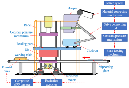
The main structure of the block forming machine is shown in Figure 1, composed of an oil cylinder, a frame, a mould, a worktable, a worktable, a forming brick, an exciting mechanism, a composite magnetorheological shock absorber, a plate feeding mechanism, a supporting plate, a distribution car, a driving connecting rod, a material conveying mechanism and a hopper.
|
| Figure 1. Structure of a block forming machine |
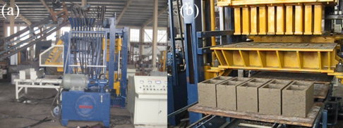
The block-forming machine adopts the table vibration mode. Five standard blocks are produced at a time, and the production cycle is 15 s. The working process of the block-moulding machine is as follows. The conveyor belt sends the mixed material to the hopper, and the distributor car sends the material to the mould. The bracket is on the bottom plate of the lower part of the mould, and the mould drops until the bracket is pressed. The exciter vibrates, and the pressure maintained by the cylinder makes the die hold. The composite magnetorheological damper begins to reduce the body vibration of the block-moulding machine. The materials in the mould are compacted under the vibration of the workbench. The transported pallet enters the next unit structure under the action of the brick-out mechanism to realize automatic production of the entire block. Figure 2 shows the scene photos of the block forming machine and the block vibration compaction forming machine of the hydraulic excitation system, in which Figure 2 (a) refers to the whole machine photo of the block forming machine, including the hydraulic station, the electrical control cabinet and the material conveyor belt, and Figure 2 (b) shows the block pressed by the block forming machine that can produce five pieces at one time.
|
| Figure 2. Field drawing of block forming machine |
Vibration compaction theory can be summarized as follows. Under the action of vibration, the internal resistance of the vibrating mixture decreases sharply, the shear stress decreases, and the mixture is easy to compact under the action of its own gravity. In the block-moulding machine operation, the main components of concrete material compaction moulding are the vibration body of the shaking table and the pressure head above the bench. The vibration body mainly includes the concrete material, mould box and exciter. The main role is played by the vibration body of the shaking table. The pressure head above the mould box plays a static pressure role to press the block moulding.
2.2 Mathematical model of a vibration system
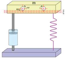
The exciter of the shaking table is mainly composed of a pair of synchronous and reverse rotating shafts. The horizontal component force offsets the same rotating shaft, and the rotating shaft is equipped with the same eccentric block. When the exciter starts to work, it generates a constant eccentric force, which is also called exciting force. The direction of the eccentric force changes at all times, and the motion is decomposed into horizontal and vertical motions in the vertical plane. Analysis shows that the vertical movement plays a major role in the compaction effect of concrete materials. Therefore, in actual production, double-shaft synchronous reverse rotation is mainly used; that is, the two shafts of the exciter are driven by the hydraulic motor, as shown in Figure 3.
|
| Figure 3. Simplified model of a vibration system |
One end of the damping spring is connected to the fixed frame, and the other end is connected to the vibration body with mass of . When no load exists, the movement end of the spring is located at . When the vibration body is added, the movement end of the spring changes from to , and the static deformation of the spring is
|
|
(1) |
|
|
(2) |
where is the gravity, and is the spring elastic force.
When the exciter works, the position of the spring movement end changes again under the excitation force, and the position of the spring movement changes. Assuming that the excitation force is , it is generated by a pair of eccentric block groups with reverse rotation. Assuming that the mass of each eccentric block group is , the eccentricity is , and the angular velocity of the eccentric block rotation is ω. The eccentric force generated by each eccentric block group can be calculated according Eq. (3) [20]
|
|
(3) |
When , the eccentric force component generated by each eccentric block group in the vertical direction is at any time, such that the resultant force of two eccentric block groups in the vertical direction is . The resultant force in the horizontal direction is 0; that is, the shaking table excitation force can be expressed as Eq. (5)
|
|
(4) |
|
|
(5) |
3. Structure design of a composite magnetorheological damper
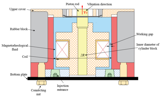
In accordance with the structure and vibration reduction requirements of a block-moulding machine, a special composite magnetorheological damper is designed, the structure and working principle is shown in Figure 4. The damping value of the composite magnetorheological damper can be adjusted, with the damping of the original rubber damper as the upper and lower 20% of the intermediate value.
|
| Figure 4. MR damper structure |
3.1 Calculation model of damping force for the composite magnetorheological damper
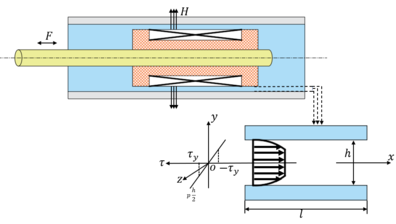
The composite magnetorheological damper adopts the flow–shear mixed mode, and its working principle is shown in Figure 5. When the piston moves in the working cylinder, the magnetorheological fluid flows through the damping channel, and the current is applied to the coil to change the external magnetic field. The magnetorheological effect occurs in the magnetorheological fluid, and the resistance of the piston changes; that is, the damping force of the damper changes. When the current is larger, the greater the external magnetic field intensity generated by the magnetorheological damper, the greater the damping force generated.
|
| Figure 5. Flow–shear mixed mode diagram |
In the analysis of the flow characteristics of the magnetorheological fluid, the flow in the tube of the magnetorheological damper is simplified to the flow between parallel plates. In fact, when considering the working state of the damper, the flow area between the piston rod and the cylinder is πDL, which is equivalent to the flow area between the plates. is the diameter of the centre of the gap between the damper piston rod and cylinder; , where and are the radii of the cylinder and piston rod, respectively; and is the effective working length of the piston. The damping force of the flow–shear mixed mode can be expressed as the sum of the differential pressure flow damping force and the shear damping force [21]
|
|
(6) |
|
|
(7) |
|
|
(8) |
where denotes the plate width, denotes the plate length, denotes the distance between two parallel plates, denotes the shear rate, denotes the yield stress, and denotes the concentration of the magnetorheological fluid.
The damping force of shear flow between plates can be calculated using Eq. (7), and the plate area in Eq. (7) is replaced with the area between circular tubes, which can be expressed as:
|
|
(9) |
Ratio of Coulomb damping force can be obtained as:
|
|
(10) |
Ratio of viscous damping force can be obtained as:
|
|
(11) |
The viscous damping force and Coulomb damping force of shear flow are considerably less than those of differential pressure flow. Therefore, the damping force of the flow–shear hybrid magnetorheological damper can be approximately calculated using the damping force of the differential pressure flow magnetorheological damper.
|
|
(12) |
The elastic force of the rubber block is calculated as:
|
|
(13) |
The damping force of the composite magnetorheological damper is the sum of the elastic force of the rubber block and the damping force of the differential pressure flow magnetorheological damper
|
|
(14) |
3.2 Parameter determination of the magnetorheological damper
The composite magnetorheological damper is mainly composed of piston rod, rubber pad, cylinder body, magnetorheological fluid and coil. The maximum stroke of the piston rod is 3 mm. In practical application, the maximum amplitude of vibration is less than 1.6 mm, generally approximately 1 mm, which can fully meet the actual needs. Four copper pins are uniformly installed on the piston rod and the lower piston head (turning after installation) to guide. The cylinder is filled with a magnetorheological fluid. The magnetorheological fluid is injected from the hole in Figure 4, and two injection holes exist. When the magnetorheological fluid is injected, the two internal hexagon screws should be rotated out, from one hole to the magnetorheological fluid flowing out of the other hole, which shows that the magnetorheological fluid has filled the entire cylinder. The rubber block in the figure acts as a reset, equivalent to a spring. The coil is surrounded on the coil skeleton, and two coils are drawn out from it. The magnetic field intensity inside the magnetorheological fluid can be changed by adjusting the strength of the current to control the damping force. The composite magnetorheological damper and the upper and lower plates are connected by screws. The upper plate connection is locked by a screw through the hole in the upper plate to the thread hole in the middle of the piston rod, and the lower plate connection is locked by two screws. The main working principle is that the vibration is transmitted to the piston through the piston rod, and the magnetic field is changed by adjusting the coil current embedded in the piston. Under different magnetic fields with various intensities, the magnetorheological fluid exhibits distinct yield stresses, thus playing buffering and damping roles. The core components of the composite magnetorheological damper are cylinder, magnetorheological fluid and coil, and the corresponding design parameters are cylinder diameter D1, working clearance h and magnetic circuit effective length . In the test, the specification model of the magnetorheological fluid used in this paper is MRF15C, specific parameters as shown in Table 1.
| Basic parameters | Mass solid content | Density (g/cm3) | Apparent viscosity (200s-1) | Saturated shear yield strength (kPa) | Thixotropic cracking index | Operating temperature (C) |
|---|---|---|---|---|---|---|
| 70% | 2.77 | 0.09 | 36.9 | 0.22 | -40~150 |
3.2.1 Properties of rubber materials
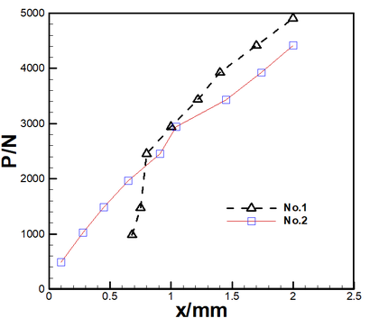
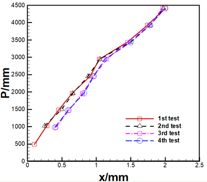
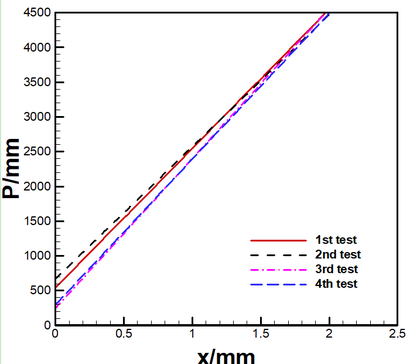
The magnetorheological damper designed in this study retains some rubber materials in the original rubber block damper as reset elastic elements. Performance tests of the two rubber damping materials used in the original concrete block-moulding machine are conducted. The Shore hardness of the two materials is 85. Figure 6 shows a performance comparison between samples 1 and 2. Figure 7 is the result of four loading tests for sample 2, and Figure 8 is the elastic coefficient of rubber block fitted from the four loading tests. The experimental results show that the rubber damping block begins to deform after loading 436.23 N on average, and the average elastic coefficient is 2039.43 N/mm, which presents a linear relationship.
|
| Figure 6. Pressure experiment result of rubber damper sample 1 and sample 2 |
|
| Figure 7. Experiment result of load for sample 2 |
|
| Figure 8. Matched spring rate of sample 2 |
Rubber blocks absorb vibrations in different directions. When the magnetorheological damper maintains a balanced piston position, it has sufficient shear motion space to play a damping role. In the absence of current, zero magnetic field, it plays a damping function to meet the general operating conditions.
3.2.2 Working clearance between piston and cylinder 3.2.2 Working clearance between piston and cylinder
h
{\textstyle {\mathit {\boldsymbol {h}}}}
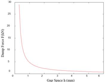
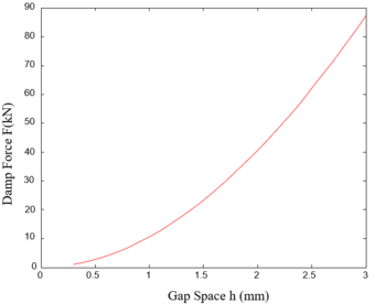
When the working gap between the piston rod and cylinder block increases, the output of the damper will decrease, but the dynamic adjustment multiple will increase. Therefore, the balance between the damping force and the dynamic adjustment range should be considered in the design. The relationship between damping force and working gap is shown in Figure 9, and the relationship between dynamic adjustment range and working gap is shown in Figure 10.
|
| Figure 9. Relationship between damping force with gap space |
|
| Figure 10. Relationship between dynamic range with gap space |
The size of the working clearance directly affects the damping force of the composite magnetorheological damper, the damping force of the composite magnetorheological damper decreases nearly linearly with the increase in the working clearance , and its influence is greater than the effective area of the piston . The reason is that the magnetic field intensity generated by the damper coil will decrease sharply with the increase in working gap . Thus, in the design of a composite magnetorheological damper, to increase the damping force, the working gap should be as small as possible. However, due to the decrease in the working clearance of the composite magnetorheological damper, the viscous damping will increase rapidly, and the adjustable range of the damping force will decrease rapidly. Accordingly, the working clearance should be properly selected. In accordance with the previous experience design, the working gap is generally 0.8-2 mm. This study considers =1 mm in consideration of actual situation.
3.2.3 Diameter of cylinder and piston
In accordance with the GB2348-80 standard, the working cylinder thickness and the inner and outer diameters of the cylinder are determined as follows:
|
|
(15) |
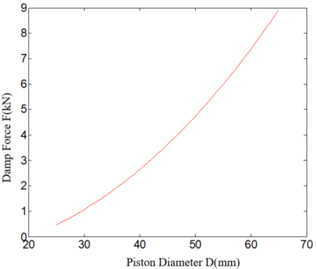
Where denotes the rated pressure, denotes the allowable stress, and denotes the initial inner diameter of the working cylinder. The maximum load kN in accordance with the allowable stress MPa. Cylinder inner diameter : The effective area is determined by the cylinder inner diameter . As shown in Figure 11, the larger the effective area of the piston is, the greater the damping force will be. Therefore, to obtain a shock absorber with large energy consumption, the cylinder inner diameter should be selected as large as possible. However, given that the adjustable multiple of the damping force decreases with the increase in the effective area , the increase in the diameter also increases the unadjustable viscous damping force of the damper and makes the structure cumbersome. The effective area of the piston determines the static bearing capacity of the shock absorber. Under other same working conditions, the greater the effective area of the piston is, the greater the pressure requirement for working will be. The initial inner diameter mm, the calculated working cylinder wall thickness mm, and mm. The ratio of the thickness of the working cylinder to the inner diameter of the working cylinder is , the inner diameter of the cylinder is 40 mm, and the outer diameter is 52 mm.
|
| Figure 11. Relationship between damping force with piston diameter |
The calculated value is the diameter at the most vulnerable position of the rod because the outlet hole of the coil with an inner diameter of 4 mm should be drilled on the piston rod. To increase the magnetic field channel and avoid the influence of the magnetic saturation of the piston rod on the working performance, the diameter of the piston rod is mm.
3.2.4 Magnetic circuit design
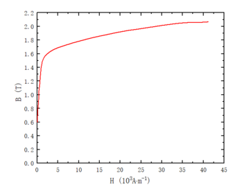
The composite magnetorheological damper adopts a single-stage magnetic circuit structure. The coil is acetal enamelled copper wire, with diameter mm and turns of 800. Class E insulation is adopted, such that the allowable limit temperature rise is 80 °C. Considering that the copper wire is immersed in the magnetorheological fluid, the heat dissipation coefficient of the coil is W/(m2 °C), and the filling coefficient of the coil is . DT4 electrical pure iron is used in magnetic components, such as external magnetic ring and magnetic core, and the B-H curve is shown in Figure 12.
|
| Figure 12. B-H curve distribution |
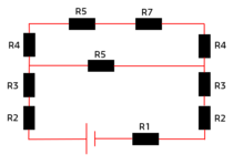
In the case that each section of the magnetic circuit is not saturated, the increase in the effective length of the piston magnetic circuit section causes increased magnetorheological fluid to produce a magnetorheological effect, which is proportional to damping force. However, if the effective length is excessively large, the magnetic field intensity at the working gap will decrease and the distribution is uneven, resulting in magnetic leakage. Therefore, under normal conditions, the choice of should satisfy . On the basis of actual work, this study chooses = 44 mm. The magnetoresistance distribution of the composite magnetorheological damper is shown in Figure 13. In the figure, is the magnetoresistance of the magnetic core. is the magnetoresistance of yoke. is the magnetoresistance in the lower half of the working gap. is the magnetorheological fluid reluctance in the upper half of the working gap. is the partial reluctance at the edge of the working cylinder. is the magnetorheological fluid magnetoresistance. Magnetorheological fluid magnetoresistance exists in the upper half of working gap.
|
| Figure 13. Magnetoresistance distribution map |
The calculation formula of magnetoresistance is [22]
|
|
(16) |
where is the relative permeability, and is the area where the magnetoresistance is produced. The magnetoresistance can be calculated using the following formula. The magnetorheological damper working magnetoresistive sum can be calculated as:
|
|
(17) |
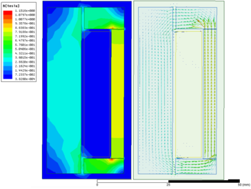
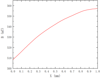
In the finite element analysis, given that the structure and magnetic circuit of the magnetorheological damper are a typical axisymmetric structure, half of its model is considered for simplified modelling analysis, without considering the leakage problem [23]. The above initial parameters are passed through the Maxwell finite element performance optimisation module. The coil current is 1 A, and the number of turns is 800. The corresponding magnetic circuit finite element model is established, as shown in Figure 14. Figure 15 depicts that the magnetic induction intensity in the damping channel changes in a curve between 505 and 560 mT, which meets the requirements for magnetic field intensity under working conditions.
|
| Figure 14. Magnetic field and magnetic line distribution of the magnetorheological damper |
|
| Figure 15. Magnetic field distribution curve of the working gap |
4. Experimental analysis on the application performance of composite shock absorber in block forming machine
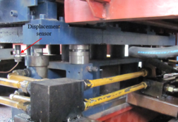
All the experiments are carried out automatically by a PC on the platform. The virtual instrument hardware used in the experiment is the data acquisition card NI-6014 of American national instrument company (NI) and its matching terminal board . Other experimental equipment include PC, DC power supply, and acceleration sensor and displacement sensor each. Figure 16 shows the field picture of the installation of the displacement sensor for the vibration test of the block forming machine.
|
| Figure 16. Field test and installation diagram of displacement sensor |
To understand the influence of adjusting and on the exciting parameters in the hydraulic vibration technology, the vibration amplitude and acceleration of the vibrating plate during compaction were measured by a vibrometer in the experiment. Firstly, the air vibration test of the block forming machine is carried out. At the same frequency, the test data are shown in Table 2.
| P (MPa) | Q (L/min) | Frequency (Hz) | Vibration amplitude (mm) | Acceleration (g) |
|---|---|---|---|---|
| 11 | 99 | 28.81 | 1.2 | 6.2 |
| 12 | 90 | 1.0 | 5.7 | |
| 12 | 99 | 1.3 | 6.3 | |
| 13 | 99 | 1.4 | 6.8 |
The experiment carries on the feeding test to the block forming machine. In the test process, the debugger adjusts the parameter unceasingly, when the frequency converter is displayed as 40.94 Hz, the concrete brick quality is better. In the process of debugging, the vibration frequency has a great influence on the vibration parameters.
Table 3 shows that the vibration amplitude increases with the pressure and decreases with oil pressure , and the effect of adjusting pressure on vibration amplitude is more significant than that of adjusting oil pressure .
| P (MPa) | Q (L/min) | Frequency (Hz) | Vibration amplitude (mm) | Acceleration (g) |
|---|---|---|---|---|
| 12 | 99 | 40.94 | 1.34 | 10.3 |
| 13 | 99 | 1.4 | 11.2 | |
| 14 | 99 | 1.55 | 12 | |
| 14 | 90 | 1.32 | 10.7 |
In the test experiment, adjusting the rotational speed of the mechanical vibration of , and hydraulic motor and through the communication with the field technicians, the amplitude of the vibration plate of mechanical vibration is generally between 0.6 and 0.7, and the acceleration is 8 or 9 g. The data obtained from the field test are in this range.
The comparison of the two vibration technologies shows that the hydraulic vibration technology can obtain higher vibration amplitude and vibration acceleration. Furthermore, the hydraulic vibration has a wide range of adjustment, convenient adjustment and wider application range. The timeliness of starting and stopping vibration of hydraulic vibration is high, and obvious difference are observed compared with the starting and stopping of mechanical vibration.
Comparison of driving mechanism: the energy mechanism of mechanical vibration is detailed as follows: two hydraulic motors, model 25MCM14-1B, displacement 25 , rated pressure 32 MPa and driving power 24.6 kw. The energy mechanism of hydraulic vibration is hydraulic station motor: three-phase asynchronous motor, type Y180LMY4, power 22 kW, working voltage 380 V and working current 42.7 A. Rotary valve motor: three-phase asynchronous motor, model Y90LMUI 4, power 1.5 kW, working voltage 380 V and working current 3.65 A. Between the two vibration modes, hydraulic vibration is more energy-saving.
4.1 Study on excitation high order spectrum analysis
The vibration system of the block forming machine is a typical nonlinear and non-Gaussian system, and the autoregressive high-order spectrum contains the essential characteristics of the vibration system. The autoregressive high-order spectrum model is used to study the one-dimensional slice spectrum of autoregressive bispectrum, trispectrum and their bispectrum, two-dimensional slice spectrum, diagonal slice spectrum and one-dimensional slice spectrum of autoregressive bispectrum. It is applied in the analysis of dynamic and nonlinear characteristics of block forming machine vibration system and magnetorheological damping system [24,25]. Through the spectral analysis under different working conditions, not only the energy information of the system can be obtained, but also the phase coupling information and nonlinear characteristics of the system under different working conditions. As a result, the relationship between excitation and damping parameters and vibration spectrum characteristics can be determined.
According to the failure pressure of concrete hollow block in Table 4 and the comparison of the table data, for hydraulic vibration, the compressive strength of concrete block produced by block forming machine is the best under the vibration parameters of flow L/min and pressure MPa.
| Serial number | Flow (L/min) | Pressure (MPa) | Bear the pressure (KN) | |
|---|---|---|---|---|
| Group 1 | Group 2 | |||
| 1 | 90 | 13 | 105.53 | 89.22 |
| 2 | 90 | 14 | 106.53 | 72.93 |
| 3 | 99 | 13 | 110.28 | 89.67 |
| 4 | 99 | 14 | 113.99 | 96.00 |
Figure 17 AR spectrum, BS represents double slice, TS represents triple slice. From the analysis of the Figures 17AR spectrum of the chart, under different oil pressure , the slice diagram between them shows that the position of the highest wave peak only changes slightly, whilst the other secondary wave peaks will change obviously with the oil pressure . These changes are mainly concentrated in the amplitude and position. The overall trend shows that with the decrease in oil pressure , the amplitudes of other sub-peaks relative to the highest peak are generally increasing. The reason is that with the decrease in oil pressure , the vibration signal energy used for block vibration compaction decreases, thereby making some other vibration signal energy more prominent. The slice diagram is compared under different flow : generally, the position of the highest peak only changes slightly, whereas the other secondary peaks change obviously with the flow These changes are mainly in the amplitude and position. The overall trend shows that with the decrease in traffic , the amplitudes of other sub-peaks relative to the highest peak are generally increasing, and more wavelet peaks are observed. With the decrease in flow rate , the vibration signal energy used for block vibration compaction becomes smaller, thereby making other vibration signal energies more prominent. For hydraulic vibration, the frequency and amplitude composition of the signal components in vibration compaction is the most ideal, or the vibration process is the most stable when the rate is flow L/min and pressure MPa.
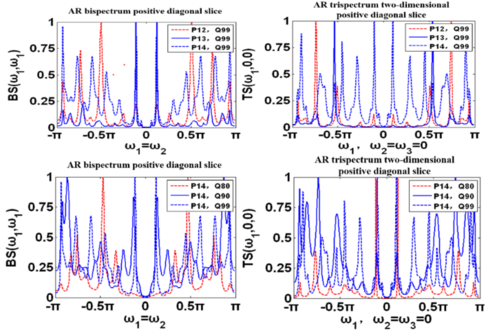
|
| Figure 17. Comparison of regulating pressure and flow slice diagram |
In summary, the excitation and damping parameters in hydraulic vibration should be adjusted to achieve the best quality of the production block, and the effect that the vibration and noise signal should be as small as possible in the process of vibration compaction. For hydraulic vibration, the composite magnetorheological shock absorber is used to replace the original rubber shock absorber when the flow rate is flow L/min and pressure MPa. When no and small currents are observed, the damping force of the composite magnetorheological shock absorber is less than that of the original rubber shock absorber. By taking this measure, more vibration energy is used in vibration compaction, thereby reducing the noise signal.
4.2 High-order spectrum analysis of vibration reduction
The common rubber shock absorber is compared with the composite magnetorheological shock absorber with different currents. Through the preliminary test and reference [25], the current is selected 0A, 0.5A and 1A, as shown in Figures 18 to 21. The spectrum of the common rubber shock absorber is different from that of the composite magnetorheological shock absorber with different currents. The damping parameters of the composite magnetorheological shock absorber are designed according to the original rubber shock absorber, but differences in the pattern are evident due to the action of magnetorheological fluid in the composite magnetorheological shock absorber. However, the main difference is the peak size of some peaks and the overall stationarity of the vibration wave:
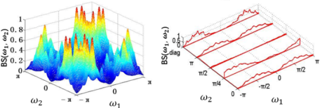
|
| Figure 18. Rubber shock absorber-AR bispectrum amplitude and bispectrum slice diagram |
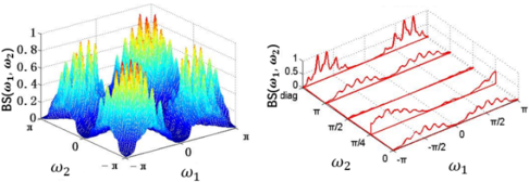
|
| Figure 19. . Composite magnetorheological shock absorber-AR bispectrum amplitude and bispectrum slice diagram |
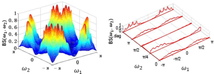
|
| Figure 20. . Composite magnetorheological shock absorber-AR bispectrum amplitude and bispectrum slice diagram |
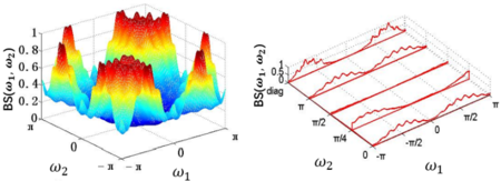
|
| Figure 21. . Composite magnetorheological shock absorber-AR bispectrum amplitude and bispectrum slice diagram |
The AR bispectrum amplitude and bispectrum slice characteristics of the rubber shock absorber and composite magnetorheological shock absorber are compared and analysed. In Figures 18-21, the bispectrum amplitude map is more intuitive, and the bispectrum amplitude map is symmetrical, but the spectral peaks are obviously different. At , the secondary peak of composite magnetorheological shock absorber increases compared with that of rubber shock absorber, and the increase in the number of secondary peaks indicates that the nonlinearity of the system is gradually enhanced. In the bispectrum slice, an obvious peak at diag and the maximum coupling occurs, indicating that the energy distribution is strong here. The peak at = /2 is suppressed, the degree of coupling is low, and the energy distribution is weak. When , the number of subpeaks of AR bispectrum amplitude decreases and the spectral peaks become thicker. At , the peaks are thick, and the number of peaks increases, whereas the number of secondary peaks decreases. In the bispectrum slice, an obvious peak is observed at diag, and the maximum coupling occurs, indicating that the energy distribution is strong here. The peak at = /2 is suppressed, the degree of coupling is low, and the energy distribution is weak here. At =0, /4, , the peak distribution is relatively uniform, and the energy distribution is relatively uniform. In Figures 18-21, when , the component of the slice signal is high, the amplitude distribution is more stable. The reason for the analysis is that the damping effect of the composite magnetorheological shock absorber is not proportional to the magnitude of the electrified current, and the vibration can be best when the is appropriate. Through the study of the high-order spectrum of magnetorheological shock absorber, it is of guiding significance to study the selection of electrified current of composite magnetorheological shock absorber under different working modes.
In this paper, the material ratio of concrete hollow block is approximately 10% of cement and 90% of stone powder. The hollow blocks made of the same specification parameters are tested. The first group uses composite magnetorheological shock absorber, and the current is 0.5A, and the second group does not use composite magnetorheological shock absorber. The timing begins when the work of the upper hydraulic cylinder drops. The hydraulic cylinder to the lower end of the hydraulic cylinder takes 2 to 3 s to encounter the hollow brick, and then the hydraulic oil pressure in the hydraulic cylinder begins to rise slowly. At the beginning of the pressure rise, a slight drop, which is caused by the uneven surface of the concrete hollow block, occurs. As the cylinder drop pressure continues to rise to a certain value, it reaches the peak, and then as the cylinder drops, the pressure continues to drop. When the pressure is reduced by 2% of the maximum value, the computer determines that the hollow block has been damaged. Automatically, the maximum value of the pressure during the whole period is recorded as the failure pressure. In Figure 22, we can clearly see obvious cracks on the surface of the concrete hollow block after it has been destroyed.
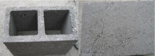
|
| Figure 22. Block diagram after failure |
The test results in Table 4 show that the compressive strength of concrete hollow blocks produced under the same conditions cannot be completely consistent, but the compressive strength of concrete hollow blocks produced by composite magnetorheological shock absorbers in the first group is higher than that of concrete hollow blocks produced without composite magnetorheological shock absorbers in the second group, and the compressive strength of concrete hollow blocks produced by composite magnetorheological shock absorbers in the first group is higher than that in the second group without composite magnetorheological shock absorbers, and when the flow L/min, and pressure is MPa. The compressive strength of the produced concrete hollow block has the best consistency with the test data.
Conclusions
1. In this paper, a composite magnetorheological damper structure is designed, the optimal structural parameters are determined, and the experimental data are collected. The experimental results show that the design can meet the requirements, and the use effect is good.
2. The hydraulic excitation structure can achieve high vibration amplitude and acceleration. The hydraulic vibration regulation range is large and easy to adjust. The hydraulic vibration shock and stop time are high. When the flow rate L/min and pressure MPa, the quality of the production block is the best. The vibration and noise signal in the process of vibration compaction should be as small as possible.
3. Through the high-order spectrum analysis of the composite magnetorheological shock absorber, we can know that the AR bispectrum amplitude and bispectrum slice signal composition, system phase coupling and energy distribution are the best (stable) in to achieve a better damping effect.
Acknowledgments
This project has been supported by: the Natural Science Foundation of Fujian Province (grant no.2023J01342), the Program for Innovative Research Team in Science and Technology in Fujian Province University (2020No.grant: no.12). Fujian Provincial Key Project of Science and Technology Innovation (2022G02007) and High-level talents foundation of Fuzhou Polytechnic (grant no. 350 FZYRCQD 201903). National Natural Science Foundation (52275413).
References
[1] Liu X.Y., Li X.H. Design of hydraulic system of building block forming mnachine based on PLC. J. Machine Tool and Hydraulic Pressure, 45(02):106-109, 2017.
[2] Yao C.F. Study on vibration mode of block forming machine. J. Modern Manufacturing Technology and Equipment. 5:56-57, 2018.
[3] Zhan S.W. Theoretical discussion on the design of vibration system of concrete block forming machine. J. Building Blocks and Block Buildings, 03:30-32, 2015.
[4] Wu Q.M., Zhang Q., Zhang C., Song C. Vibration mode and harmonic response analysis and design improvement of block forming machine. J. Mechanical Design, 10:73-76, 2008.
[5] Zhong M.D. Vibration system Analysis of concrete block forming machine based on ADAMS. J. Sichuan Cement, 10:52-53, 2020.
[6] Li S.T. Upgrade and optimization of automatic block forming machine based on Mitsubishi PLC and vinylon touch screen. J. Electromechanical Information, 23:51-53, 2020.
[7] Huang Q.Z., Huang Y.J., Zhuang J.S. Design of hydraulic excitation system of concrete block forming machine. J. Hydraulic and Pneumatic, 02:127-131, 2014.
[8] Zhuang J.S., Huang Y.J., Wu F.S. AR bispectrum characteristics of block forming machine’s vibration driven by hydraulic exciter. Advanced Materials Research, 295-297:2249–2253, 2011.
[9] Zhuang J.S., Huang Y.J. Autoregressive bispectrum analysis of vibration signal of block forming machine. J. Machine Tool and Hydraulic Pressure, 38:138-141+108, 2010.
[10] Su C.J., Wang W.W., Guo S.M., Zhang G.H. Design and vibration characteristic analysis of chaotic vibration exciter for block forming. J. Mechanical Design and Manufacture, 06:195-198, 2014.
[11] Long X.H., Ma Y.T., Yue R., Fan J. Experimental study on impact behaviors of rubber shock absorbers. Construction and Building Materials, 173:718–729, 2018.
[12] Jugulkar L.M., Singh S., Sawant S.M. Fluid flow modeling and experimental investigation on automobile damper. Construction and Building Materials, 121:760–772, 2016.
[13] Sassi S., Cherif K., Mezghani L., Thomas M., Kotrane A. An innovative magnetorheological damper for automotive suspension: from design to experimental characterization. Smart Materials and Structures, 14(4):811–822, 2005.
[14] Tu F.C., Yang Q., He C.C., Wang L.D. Experimental study and design on automobile suspension made of magneto-rheological damper. Energy Procedia, 16(Part A):417–425, 2012.
[15] Liao C.R., Zhao D.X., Xie L., Liu Q. A design methodology for a magnetorheological fluid damper based on a multi-stage radial flow mode. J. Smart Materials and Structures, 21(8), 085005, 2012.
[16] Wang M., Chen Z.B., Wereley N.M. Magnetorheological damper design to improve vibration mitigation under a volume constraint. Smart Materials and Structures, 28(11), 114003, 2019.
[17] Andrzej M., Mikołaj H. Application of magnetorheological fluid in industrial shock absorbers. Mechanical Systems and Signal Processing, 28:528–541, 2012.
[18] Zhou Y., Zhang Y.L. Optimal design of a shear magnetorheological damper for turning vibration suppression. Smart Materials and Structures, 22(9), 095012, 2013.
[19] Oladapo B.I., Muhammad M.A., Adebiyi V.A., Oluwole B., Usman H. Model hybrid magnetorheological damping prediction in machine tools. Engineering Structures, 213, 110621, 2020.
[20] Li P., Li Y.C., Zhou K., Li Y.Y. Summary of similar design of shaking table model test. Journal of College of Disaster Prevention Science and Technology, 22(04):29-35, 2000.
[21] Zhu S.X., Hao X.S. Establishment and experimental study of damping force model of piston magnetorheological damper. Machine Tool and Hydraulics, 47(20):20-23+27, 2019.
[22] Ma W.W., Zhou Y.Q., Jie X.S. Physics course. Beijing: Higher Education Press, 2006.
[23] Li W.N., Wu X.Y. Design of a new magnetorheological damper for machine tools and its damping performance. New Industrialization, 7(06):33-38, 2017.
[24] Wu H.S., Huang J.Y. Study on trispectrum-correlation dimension of vibration signal of magnetorheological damper. Journal of Instrumentation, 33(10):2322-2329, 2012.
[25] Chen B.S, She N, Lin D.D, Yan X.Y. Experimental study on the nonlinear vibration of a new composite magnetorheological damping system. Mechanical Systems and Signal Processing, 181, 109480, 2022.Document information
Published on 17/07/24
Accepted on 01/07/24
Submitted on 29/02/24
Volume 40, Issue 3, 2024
DOI: 10.23967/j.rimni.2024.07.003
Licence: CC BY-NC-SA license
Share this document
Keywords
claim authorship
Are you one of the authors of this document?