Muhtarklim (talk | contribs) m (1212) (Tag: Visual edit) |
m (Onate moved page Review 697782283648 to Liu et al 2024e) |
| (2 intermediate revisions by one other user not shown) | |
(No difference)
| |
Latest revision as of 10:54, 3 July 2024
Abstract: A slip film control technique based on an expansion state observer is proposed to address issues such as unclear internal characteristics of cotton-picking hydraulic equipment, modeling difficulties owing to external random disturbances, poor output speed stability, and limited controllability. First, a third-order mathematical model of the valve-controlled motor is established. Then the unmodeled model's dynamic errors and load disturbances are uniformly integrated in-to the 'total disturbances' for real-time estimation and compensated to the sliding-mode controller combined with the expanded state observer by the second-order expanded state observer, and finally, a complete valve-controlled motor system is constructed in the 'MATLAB/Simulink-AMESim' simula. The simulation test results show that the control algorithm is faster, more stable, and more resistant to interference than the PID controller and the backstepping sliding mode controller, with control accuracy improved by 94.5% and 85.6%, respectively, and hydraulic motor output with a constant rotational speed is achieved.
Key words: Expansion state observer; cotton picking head; hydraulic servo system; valve-controlled motor system; constant speed control.
1. Introduction
Cotton is one of the most important crops in the world and one of the major cash crops in China [1,2]. However, the high cost of picking cotton after maturity has greatly limited the growth of the cotton economy [2]. The cost of cotton picking machine picking cotton is much lower than manual picking, so the use of machine picking cotton can greatly accelerate the growth of the cotton economy [3]. However, the current machine picking process has the problem of unstable drum rotation, which will reduce the cotton picking rate at the same time increase the impurity rate of cotton [4,5]. The drive system of a cotton picker drum.
Hydraulic servo systems are usually difficult to describe with accurate mathematical models due to their time-varying and nonlinear characteristics [6-8]. Furthermore, the complexity of developing an accurate model may be further increased by the influence of variables such as variations in oil temperature, the type of fluid, and the accuracy with which equipment is manufactured. [9,10]. In the field of control, the more traditional approach is to use the PID control method of closed-loop control of the speed control system, which involves adjusting the proportional, differential, and integral links to achieve system control. However, the self-immune control method is introduced in this study because the traditional PID control method makes it difficult to achieve a more satisfactory control effect for this more complex valve-controlled hydraulic motor system [11-14]. Self-immunity control is a general-purpose controller focused on engineering applications that can handle unmodelable dynamics as "internal disturbances." Its main idea is to create a low-order system using dilated state observers, which can then be used to control a high-er-order system [15-17]. Zhang et al. [18] used the expanded state observer to observe the velocity, acceleration, and compound perturbations of the actuator in re-al-time. They combined it with a backstepping sliding film controller to bypass the step of accurately modeling the valve-controlled motor system. The simulation results proved that it can greatly inhibit the compound perturbations of the system and has higher accuracy and robustness. However, the expanded state observer used is of higher order, more complex to compute, and more demanding on hardware. Navale and Nelson [19] optimized a fuzzy adaptive logic controller using a genetic algorithm and evolutionary strategy to re-duce the system error; Liu et al. [20] proposed a self-resistant controller combined with a feedforward compensation algorithm for the cotton picker drum system, which greatly reduces the steady state error of the model. Still, the feedforward makes it difficult to adjust the parameters of the composite controller.
Summarizing the current state of research, it has been found that the time-varying nature of hydraulic servo systems makes them too complex to be directly applied in most cases [21,22]. This may make the system's transient response performance degrade under complex operating conditions; therefore, it is particularly important to investigate appropriate control strategies. In this paper, focusing on the study of a Electro-hydraulic Servo Valve Motor System with constant speed output of the motor as the control objective, sliding mode control based on an expanded state observer is proposed to solve the constant output problem of a single-pump, dual-valve-controlled motor system. In a way, it paves the way for a wide range of applications in practical engineering scenarios.
2. Valve-controlled motor system modeling
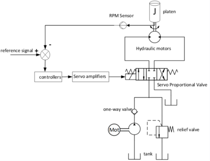
Cotton picking drum work as motor-driven quantitative pump and relief valve in parallel to form a constant pressure source to supply the servo-proportional valve stable pressure and flow, the controller receives and processes the drum feedback signals and control target signals, and then to the servo-proportional valve input control signals in or-der to achieve the control effect. Cotton picking head drum hydraulic drive system schematic diagram shown in Figure 1.
The working principle of the hydraulic servo system of the valve-controlled motor is shown in Figure 1. With the change of the spool displacement xv of the servo-proportional valve, the flow rate and pressure through the servo-proportional valve will change, and at the same time, the output torque T and the output speed θm of the hydraulic motor will also change.
From the balance equation of the moment of inertia: the motor output moment can be expressed as the moment of inertia, viscous damping moment, frictional resistance mo-ment, and interference moment, due to the rigid connection between the motor and the load between the motor and the load of the rotational error between the motor and the load can be regarded as zero, ignoring elastic moment. The mathematical expression is:
|
|
(1) |
where Jt denotes the rotational inertia of the motor load; Dm denotes the volumetric displacement of hydraulic fluid when the motor is operating; PL=P1-P2 denotes the load pressure when the motor is operating; Bm denotes the coefficient of viscous friction of the hydraulic motor; Af denotes the Coulomb friction amplitude that can be modeled; and Sf is used to describe the continuum shape function of Coulomb friction;
From the flow balance equation, the hydraulic motor inlet and outlet flow can be ex-pressed as the drive motor flow, internal and external leakage flow and motor cavity de-formation flow, and its mathematical expression is:
|
|
(2) |
Where: Ct denotes the total leakage coefficient of the hydraulic motor, βe denotes the volumetric modulus of elasticity of the hydraulic fluid, and Vm denotes the effective volume of the motor.
Due to the static hydraulic characteristics of the servo-proportional valve, the spool displacement determines the flow and pressure at the valve port, which is mathematically expressed as:
|
|
(3) |
where Cd, ω, ρ denote the flow coefficient, area gradient and density of the hydraulic fluid, respectively; Kq denotes the static flow gain of the system; Ps and Pr denote the out-let pressure and return pressure of the system hydraulic pump, respectively.
Since the response speed of the solenoid valve is much higher than that of the valve-controlled motor system, the corresponding relationship between the controller output voltage signal and the spool displacement can be regarded as an inertial link, and the mathematical expression is:
|
|
(4) |
Where: K represents the ratio of spool displacement to the controller output voltage signal.
Equations (1) to (4) define the state variables of the valve-controlled motor system: , and the state space expression of the valve-controlled motor system can be obtained as follows:
|
|
(5) |
Where:
3 Valve Motor System Controller Design
First, σi (where i = 1~2) is set for estimating the state variables x1 and x2 of the control system. in addition, σ3 denotes the estimation of the internal and external disturbances faced by the valve-controlled motor system, which vary with time t, denoted by d(t). It is assumed that the rate of change of the external disturbance σ3 is bounded, denoted as , where B is a positive boundary value. Based on the system model, the following expanded mathematical model can be obtained.
|
|
(6) |
Where:
The control objective of this paper is: the control of constant speed of the drive motor, so the third-order system of the drive motor can be simplified to a second-order system. The mathematical expression is:
|
|
(7) |
At this point, the control objective of the valve-controlled motor system can be ex-pressed as follows: the difference between the desired signal and the motor state variable x2 change is 0. The mathematical expression is:
|
|
(8) |
Where: xd denotes the desired speed.
After the valve motor system has been expanded and simplified, the following sliding mode control algorithm will be introduced to achieve the control effect. The sliding mode controller design can be expressed as:
|
|
(9) |
Let , bring within Eq. (7) into Eq. (9). The state space expression that can finally meet the system control requirements can be obtained. Its mathematical expression is:
|
|
(10) |
Further simplification leads to a new mathematical model with the desired speed error as the control variable with the following expression:
|
|
(11) |
Where:
The system parameter uncertainties, external perturbations are included in fd. In order to improve the simplicity and readability of the system, the expansion state observer is redesigned to observe it with the following mathematical expression:
|
|
(12) |
Where:
Define the sliding mold surface:
|
|
(13) |
The derivation of s and the choice of the exponential convergence rate yields:
|
|
(14) |
Where:
k1>0 and k2>0 . To make the sliding mold surface s converge to and 0, define a positive definite Lyapunov function with the expression:
|
|
(15) |
The derivation of Eq. (14) and bringing it into Eq. (10) can be obtained:
|
|
(16) |
At this point, choose the exponential convergence rate , then the sliding mode control rate can be expressed as:
|
|
(17) |
4. Coupling performance analysis of two-channel valve-controlled motor system
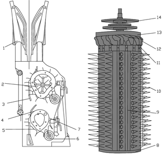
In the design of control systems, the interaction and dependence between subsystems is called coupling. In control systems, coupling refers to the mutual influence and interdependence between subsystems, while too high coupling will make the system behavior complex and difficult to control, while the coupling of the system mainly includes two aspects: state coupling of each subsystem of the system, and load coupling of each subsystem [23,24]. The roller arrangement of the cotton picker is shown in Figure 2.
Cotton enters into the cotton picking room through the grain separator, the inner space of the picking room is presented as the first wide and then narrow (one side is the grid plate, one side is the compression plate) form, cotton enters into the picking room is constantly squeezed; the other side of the grid plate is the picking drum, the drum is dis-tributed around a number of seat tubes and seat tubes around the installation of a number of spindles, spindles are installed around the drum that is, do turnover movement, and do the rotary motion and will be a regular outreach Grid plate continuously breaks the cotton bolls and wraps the cotton seeds around itself. Cotton out of the picking room by the drum into the de-cottonization area, the direction of rotation of the de-cotton disk and the oppo-site direction of rotation of the cotton picking drum, under the influence of the interaction of the seed cotton is counter-rotating off. Cotton seeds from the cotton plant after taking down through the cotton pipeline is transported to the cotton box at the same time picking spindle from the relatively static lubricator through the soil and all kinds of impurities are cleaned off at the same time picking spindle on the spindle is infiltrated with a layer of water film re-entering the picking room.
It can be seen that the coupling of the front and rear two cotton picking drums is not a hard coupling in contact with each other, and it is only necessary to estimate the load of the mutual subsystem and compensate for it.
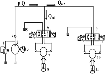
Cotton picking head drum hydraulic system is used is a single pump through two servo proportional valve supply two subsystems. The pressure and flow rate to drive the two cotton picking drums are provided by the same hydraulic pump, while the two motors are controlled by servo valves of controller 1 and controller 2 respectively, which are weakly coupled to each other. The specific hydraulic system principle is shown in Figure 3.
When analyzing the relationship between hydraulic pump outlet flow and pressure, the internal characteristics of the pump and its outlet volume characteristics need to be considered. The corresponding hydraulic pump outlet flow and pressure transfer function expression can be expressed as:
|
|
(18) |
A single dosing pump supplies flow to two valve-controlled motor subsystems. So the output flow rate Q of the pump is related to the output flow rate of the two motors in the following mathematical expression:
|
|
(19) |
The joint equations (1), (2), (3) and (19) and solved by Laplace transform are obtained:
|
|
(20) |
It is clear that the above equations represent the typical transfer functions of the valve-controlled motor systems 1 and 2, respectively, under a constant pressure source and that there is no coupling between these two channels. Due to the natural decoupling nature of the expanded state observer [25], the twin drums of the cotton picking head can be considered as two independent valve-controlled motor systems.
5. Simulation results analysis
The number of hydraulic motors of the rotating mechanism of the cotton picking system is related to the number of picking drums and the nature of the land to be picked, and there are different forms of rotating hydraulic motors of the cotton picking system at home and abroad, such as 2~6, but all of them are used in the form of harvesting one row of cot-ton with two picking drums. In this paper, the independent valve-controlled motor drive system as an example, its constant speed control objective of MATLAB/Simulink-AMESim simulation verification, the hydraulic subsystem used in the system parameters shown in Table 1.
| model parameter | Model values | Model parameter units |
| J | 0.2 | Kg·m² |
| Dm | 10-5 | m3/rad |
| Ct | 10-12 | m3/(s×pa) |
| Ps | 107 | pa |
| Bm | 90 | (N×m×s)/rad |
| Βe | 108 | pa |
| Kt | 1.19×10 | m3/(s×V×pa1/2) |
| Vt | 1.6×10⁻⁴ | m3 |
The quality of cotton picking is affected by the ratio K of the linear speed of the picking drum to the operating speed, and a suitable speed ratio K ensures that the residence time of the cotton on the drum is moderate, so that the cotton is neither over-squeezed nor incompletely picked due to too short a residence time [26]. The mathematical expression for the roller speed ratio K is:
|
|
(21) |
Where: K for the cotton picker drum speed coefficient (1.0 ~ 1.3); for the drum angular speed; R indicates the cotton picking drum radius; v indicates the operating speed of the cotton picker (5 ~ 7 km / h). Therefore, the simulation experiments will picking drum motor angular speed design for 100 r/min.
In order to verify the stability, robustness, disturbance immunity, and control complexity of the control strategy proposed in this study, three different controllers are selected for comparative analysis: firstly, the PID controller, which is widely used in engineering practice; secondly, the inverse-stepping sliding mode controller; and finally, the sliding mode controller integrated with an expanded state observer (ESO). The addition of external disturbing forces and command signals, the programming of the controller algorithms and the collection of the simulation data are performed in the MATLAB/Simulink environment.
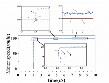
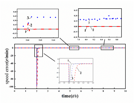
From Figure 4, it can be seen that when the 2nd second step response occurs, the response stabilization times of the expanded state observer-based sliding film controller, backstepping sliding film controller and PID controller are 0.06s, 0.36s and 0.13s, respectively; from the 2nd to the 5th second the system is subjected to sinusoidal disturbances of simulated fluctuating loads with amplitude of 30, and the three control algorithms are able to reach a stable state, and combined with Figure 5, it can be seen that at this time The sliding mode control algorithm based on the expanded state observer and the backstep-ping sliding film control algorithm basically have no tracking error, and the stabilization error of the PID controller is basically stabilized at 0.35 r/min; at the 5th second, a step signal with amplitude of 50 is added to the simulated fluctuating load without canceling the fluctuating load, and at this time, the maximum fluctuation of the sliding mode control algorithm and the backstepping sliding film control algorithm based on the expanded state observer is 0.35 r/min, the maximum fluctuation of the amplitude and the time to re-store stability are 0.35 r/min. The maximum fluctuation amplitude and the time to restore stability are 0.05r/min, 0.2r/min and 0.018s, 0.025s respectively, while the maximum fluctuation amplitude of the PID control algorithm is 0.4r/min and there is always a steady state error of 0.2r/min. It can be seen that the sliding mode control algorithm based on the expanded state observer is superior to the backstepping sliding film control algorithm and PID control algorithm in terms of rapidity, interference resistance and stability; the resulting data are analyzed as shown in Table 2.
1-expanded state observer based sliding film controller; 2-backstepping sliding film controller; 3-PID controller.
Figure 4. Comparison of speed tracking results
1-expanded state observer based sliding film controller; 2-backstepping sliding film controller; 3-PID controller.
| Control methods | Stabilisation time | maximum fluctuation | |
| step input | stalled load | ||
| ESO-based Sliding Film Controller | 0.06s | 0.018s | 0.05r/min |
| Backstepping Sliding Film Controller | 0.36s | 0.025s | 0.2r/min |
| PID controller | 0.13s | - | 0.4r/min |
In order to evaluate the effectiveness of the three control algorithms more comprehensively, the speed tracking errors in Figure 5 are now analyzed in terms of data, and two performance evaluation metrics, the mean of the absolute error and the standard deviation of the absolute error, are introduced:
The mean of absolute error is used to measure the average level of error of a control system over a series of data; its mathematical expression is:
|
|
(22) |
The standard deviation of absolute error is a statistical measure of the volatility of error in a control system. It reflects the degree of dispersion of the deviation between the actual output value and the desired output; its mathematical expression is:
|
|
(23) |
The results show that the performance of the sliding mode control algorithm based on the dilated state observer is optimal in the two indexes of control accuracy and degree of discretization, which are higher than the PID controller and the backstepping sliding mode controller by about 94.5%, 85.6% lower by about 91.6%, and 94.6%, respectively. The specific data analysis results are shown in Table 3.
| Control methods | EAve | EAbe |
| ESO-based Sliding Film Controller | 1.6×10⁻⁴ | 1.6×10⁻⁴ |
| Backstepping Sliding Film Controller | 1.5×10⁻³ | 1.9×10⁻³ |
| PID controller | 1.3×10⁻³ | 8.2×10⁻⁴ |
6. Conclusion:
In this paper, a sliding mode control method based on the expansion state observer is proposed for the constant speed drive problem of the hydraulic system of cotton picking head, and its simulation analysis is carried out, and the following conclusions are drawn.
(1) Aiming at the problem of difficult modeling of hydraulic servo system, an expansion state observer is designed to estimate the hydraulic servo system of cotton picking head in real time and feed back to the slip film controller combined with the expansion state observer, which greatly improves the control accuracy and robustness of the motor.
(2) The test platform of the electro-hydraulic servo systems was established using the MATLAB/Simulink simulation platform. Single-channel step, fluctuating load, and fluctuating + mutating load simulation tests were carried out, respectively, and the mean of absolute error and the standard deviation of absolute error were used as the criteria to compare the three controllers in terms of rapidity, robustness, and stability. The experimental results show that the sliding film control algorithm based on the dilated state observer improves the control accuracy by about 94.5% and 85.6% and reduces the degree of discretization by about 91.6% and 94.6%, respectively, compared with the commonly used PID control algorithm in engineering and the traditional inverse-stepping sliding film control algorithm.
Reference
[1] Wang X., Li Y., Feng H., Yu Q., Fan X., Liu C., Chen J., Yang Z., Biswas A. Combining Biochar with Cotton-Sugarbeet Intercropping Increased Water-Fertilizer Productivity and Economic Benefits under Plastic Mulched Drip Irrigation in Xinjiang, China. Ind. Crops Prod., 192:116060, 2023.
[2] Feng L., Chi B., Dong H. Cotton Cultivation Technology with Chinese Characteristics Has Driven the 70-Year Development of Cotton Production in China. J. Integr. Agric., 21:597–609, 2022.
[3] Sun L., Ma B., Liu T. Study on the niche mechanism of weeds in cotton field under drip-irrigated and machine-harvested in North Xinjiang. Cotton Science, 36(1):66–78, 2024.
[4] Li T., Hao F., Han Z., et al. Design and Test of Horizontal Spindle Picking Head with High Efficiency. Journal of Agricultural Machinery, 50(12):63-72, 2019.
[5] Muhetaer K., Wang J.T. Mechanical and electro hydraulic integrated design of hydraulic system of a new type cotton picker. Jiangsu Agricultural Sciences, 47(13):253–259, 2019.
[6] Yang Q., Ge S.S., Sun Y. Adaptive Actuator Fault Tolerant Control for Uncertain Nonlinear Systems with Multiple Actuators. Automatica, 60:92–99, 2015.
[7] Krstic M. On Using Least-Squares Updates without Regressor Filtering in Identification and Adaptive Control of Nonlinear Systems. Automatica, 45:731–735, 2009.
[8] Yang C., Ge S.S., Lee T.H. Output Feedback Adaptive Control of a Class of Nonlinear Discrete-Time Systems with Unknown Control Directions. Automatica, 45:270–276, 2009.
[9] Shen J., Tang Z., Wang B., et al. Constant Speed Control of Snow Removal and Salt Sprinkle Truck Based on Optimized Fuzzy Adaptive PID. Chinese Hydraulics & Pneumatics, 2019.
[10] Chen Z., Ge S., Jiang Y., Cheng W., Zhu Y. Refined Modeling and Experimental Verification of a Torque Motor for an Electro-Hydraulic Servo Valve. Chin. J. Aeronaut., 36:302–317, 2023.
[11] Ahmed M.N., Mohammed I.K., Younis A.T. Design and Implementation of PSO/ABC Tunned PID Controller for Buck Converters. Period. Eng. Nat. Sci., 9:643–656, 2021.
[12] Kim K., Rao P., Burnworth J.A. Self-Tuning of the PID Controller for a Digital Excitation Control System. IEEE Trans. Ind. Appl., 46:1518–1524, 2010.
[13] Al Sumarmad K.A., Sulaiman N., Wahab N.I.A., Hizam H. Energy Management and Voltage Control in Microgrids Using Artificial Neural Networks, PID, and Fuzzy Logic Controllers. Energies, 15:303, 2022.
[14] Beus M., Krpan M., Kuzle I., Pandžić H., Parisio A. A Model Predictive Control Approach to Operation Optimization of an Ultracapacitor Bank for Frequency Control. IEEE Trans. Energy Convers., 36:1743–1755, 2021.
[15] Han J.Q. From PID Technique to Active Disturbances Rejection Control Technique. Control Engineering of China, 2002(03):13-18.
[16] Han J.Q. Auto-disturbances-rejection controller and its applications. Control and Decision, 13(1):19-23, 1998.
[17] Jin H.Y., Liu L.L., Lan W.Y. On Stability Condition of Linear Active Disturbance Rejection Control for Second-order Systems. ACTA AUTOMATICA SINICA, 44(09), 2018.
[18] Zhang Z., Wang C., Guo X., et al. Backstepping sliding mode control of electro-hydraulic position servo system based on ESO. Journal of Beijing University of Aeronautics and Astronautics, 48(06):1082-1090, 2022.
[19] Navale R.L., Nelson R.M. Use of Genetic Algorithms and Evolutionary Strategies to Develop an Adaptive Fuzzy Logic Controller for a Cooling Coil – Comparison of the AFLC with a Standard PID Controller. Energy Build., 45:169–180, 2012.
[20] Liu Z., Muhtar K. Load feedforward and feedback constant speed control of cotton picking head hydraulic system. Machine Tool & Hydraulics, 49(24):130-134, 2021.
[21] Guan C., Pan S. Adaptive Sliding Mode Control of Electro-Hydraulic System with Nonlinear Unknown Parameters. Control Eng. Pract., 16:1275–1284, 2008.
[22] Balau A.E., Caruntu C.F., Lazar C. Simulation and Control of an Electro-Hydraulic Actuated Clutch. Mech. Syst. Signal Process., 25:1911–1922, 2011.
[23] Zheng W. Research on performance of valve controlled double stator motor speed control system. Yanshan University, 2020.
[24] Liu J. Research on Motor Walking Synchronization with Cross Coupling Control. Hydraulics Pneumatics & Seals, 43(10):59-61, 2023.
[25] Mo B. Investigation of Mathematical Modeling for Variable-displacement Pump Powered Double Valve-controlled Motor System. Journal of Basic Science and Engineering, 2002(01):77-81.
[26] Bi X., Wang W., et al. Kinematics analysis of level spindle type cotton picker drum. Research on Agricultural Mechanization, 2008(08):49-51+54.
Document information
Accepted on 02/07/24
Submitted on 24/06/24
DOI: 10.23967/j.rimni.2024.07.001
Licence: CC BY-NC-SA license
Share this document
Keywords
claim authorship
Are you one of the authors of this document?
