| (2 intermediate revisions by the same user not shown) | |||
| Line 70: | Line 70: | ||
| − | The rock surrounding the tunnel is Grade VI, which is extremely unstable. In addition, the tunnel entrance passes through a landslide, which can cause significant safety hazards such as surface settlement, collapse and landslide recovery during excavation. The middle partition method can be used to place support structures in the centre of the tunnel to provide additional support and protection, effectively controlling surface settlement and reducing the risk of rock collapse. The middle partition method involved the following sequence: (1) Part A is excavated first with temporary support in place. (2) Excavation of both Parts A and B simultaneously after excavating Part A for 2 m, with temporary support in place for both Part A and Part B. (3) Excavation of parts A, B, and C simultaneously after excavating parts B for 2 m, with temporary support in place for all three parts | + | The rock surrounding the tunnel is Grade VI, which is extremely unstable. In addition, the tunnel entrance passes through a landslide, which can cause significant safety hazards such as surface settlement, collapse and landslide recovery during excavation. The middle partition method can be used to place support structures in the centre of the tunnel to provide additional support and protection, effectively controlling surface settlement and reducing the risk of rock collapse. The middle partition method involved the following sequence: (1) Part A is excavated first with temporary support in place. (2) Excavation of both Parts A and B simultaneously after excavating Part A for 2 m, with temporary support in place for both Part A and Part B. (3) Excavation of parts A, B, and C simultaneously after excavating parts B for 2 m, with temporary support in place for all three parts. (4) Excavation of parts A, B, C, and D simultaneously after excavating parts C for 2 m, with temporary support in place for all four parts. This excavation process continues in a cyclic manner, typically with each part being excavated in a sequence of 1 m at a time. |
==3. Numerical modeling== | ==3. Numerical modeling== | ||
| Line 224: | Line 224: | ||
{| class="wikitable" style="margin: 0em auto 0.1em auto;border-collapse: collapse;width:auto;" | {| class="wikitable" style="margin: 0em auto 0.1em auto;border-collapse: collapse;width:auto;" | ||
|-style="background:white;" | |-style="background:white;" | ||
| − | |style="text-align: center;padding:10px;"| [[Image:Review_826582983555-image11.png| | + | |style="text-align: center;padding:10px;"| [[Image:Review_826582983555-image11.png|472px]] |
|- | |- | ||
| style="background:#efefef;text-align:left;padding:10px;font-size: 85%;"| '''Figure 9'''. Reduction rate of horizontal displacement in Cases II-V | | style="background:#efefef;text-align:left;padding:10px;font-size: 85%;"| '''Figure 9'''. Reduction rate of horizontal displacement in Cases II-V | ||
| Line 268: | Line 268: | ||
==References== | ==References== | ||
| + | <div class="auto" style="text-align: left;width: auto; margin-left: auto; margin-right: auto;font-size: 85%;"> | ||
| − | [1] Adam D., Markiewicz R., Brunner M., Block-in-matrix structure and creeping slope: tunneling in hard soil and/or weak rock. Geotechnical & Geological Engineering, 32: | + | [1] Adam D., Markiewicz R., Brunner M., Block-in-matrix structure and creeping slope: tunneling in hard soil and/or weak rock. Geotechnical & Geological Engineering, 32:1467–1476, 2014. |
| − | [2] Zhang Q., Wang J., Wang W., et al. Study on slope stability due to the influence of excavation of the high-speed rail tunnel. Geomatics, Natural Hazards Risk, 10(1): | + | [2] Zhang Q., Wang J., Wang W., et al. Study on slope stability due to the influence of excavation of the high-speed rail tunnel. Geomatics, Natural Hazards Risk, 10(1):1193–1208, 2019. |
| − | [3] Qin Y | + | [3] Qin Y.W., Chen Y.H., Lai J.X., et al. Failures in loess slope-tunnel system: An overview of trigging sources, acting mechanism and mitigation strategies. Engineering Failure Analysis, 158, 107996, 2024. |
| − | [4] Chen H., Lai H | + | [4] Chen H., Lai H.P., Huang M., et al. Failure mechanism and treatment measures of supporting structures at the portal for a shallow buried and asymmetrically loaded tunnel with small clear-distance. Natural Hazards, 114(2):2283–2310, 2022. |
| − | [5] Guo J.C., Li C., Analysis of the | + | [5] Guo J.C., Li C., Analysis of the construction plan for entering the mountain tunnel (in Chinese). Railway Engineering, (10):32–34, 2004. |
| − | [6] Wang H.T., Jia J.Q., Kang H.G. Analytical approach and field monitoring for mechanical behaviors of pipe roof reinforcement. Journal of Central South University of Technology | + | [6] Wang H.T., Jia J.Q., Kang H.G. Analytical approach and field monitoring for mechanical behaviors of pipe roof reinforcement. Journal of Central South University of Technology, 16(5):827–834, 2009. |
| − | [7] Bao L.L., Wei F. | + | [7] Bao L.L., Wei F. Tunnel construction in shallow soft rock using the pipe shed support. Scientific Reports, 14(1):3401–3401, 2024. |
| − | [8] Shi Y.F., Zhang T., Cao C.W., et al. Study on the | + | [8] Shi Y.F., Zhang T., Cao C.W., et al. Study on the mechanism of tunnel subhorizontal jet grouting reinforcement based on a shell model on two-parameter foundation. Journal of Engineering Mechanics, 150(4), 2024. |
| − | [9] Cai M., Xu H., Han F.Q., et al. Analysis and | + | [9] Cai M., Xu H., Han F.Q., et al. Analysis and field monitoring on surface high pressure jet grouting reinforcement in shallow-buried tunnel section. Journal of Highway and Transportation Research and Development, 40(01):152–159, 2023. |
| − | [10] Xiao J | + | [10] Xiao J.Z., Dai F.C., Wei Y.Q., et al. Analysis of mechanical behavior in a pipe roof during excavation of a shallow bias tunnel in loose deposits. Environ. Earth Sci, 75(4), 293, 2016. |
| − | [11] Ibtissem S., Mustapha A., Panagiotis S. Effect of the | + | [11] Ibtissem S., Mustapha A., Panagiotis S. Effect of the umbrella arch technique modelled as a homogenized area above a cross passage. Applied Sciences, 13(3):1588–1588, 2023. |
| − | [12] Ying H.F., Wang L.Y., Ye H., et al Layout | + | [12] Ying H.F., Wang L.Y., Ye H., et al Layout optimization of advance reinforcement of soft rock tunnel and stratum mechanical response (in Chinese). Highway, 67(06):378–385, 2022. |
| − | [13] Xu J.S., Xu H., Zhang H.T., et al. Reinforcement mechanism and parameter analysis of horizontal high-pressure rotary jet grouting piles for Tertiary semi-diagenetic water-rich sandstone tunnel. Chinese Journal of Geotechnical Engineering | + | [13] Xu J.S., Xu H., Zhang H.T., et al. Reinforcement mechanism and parameter analysis of horizontal high-pressure rotary jet grouting piles for Tertiary semi-diagenetic water-rich sandstone tunnel (in Chinese). Chinese Journal of Geotechnical Engineering, 1-10, 2024. |
| − | [14] JTG D70-2018. Specifications for | + | [14] JTG D70-2018. Specifications for design of highway tunnels: Section 1 Civil Engineering (in Chinese). China Communication Press, Beijing, 91–96, 2018. |
| − | [15] Tang J,S., Liu S,Y., Tong L,Y. The minimum safe net dis-tance between large span expressway tunnels. China Civ. Eng. 41 (12): | + | [15] Tang J,S., Liu S,Y., Tong L,Y. The minimum safe net dis-tance between large span expressway tunnels (in Chinese). China Civ. Eng., 41(12):79–84, 2008. |
| − | [16] Xiao J | + | [16] Xiao J.Z., Dai F.C., Wei Y.Q., et al. Cracking mechanism of secondary lining for a shallow and asymmetrically-loaded tunnel in loose deposits. Tunnelling Underground Space Technol., 43(7):232–240, 2014. |
Latest revision as of 11:23, 13 June 2024
Abstract
The tunnel with a large front slope is a common type of entrance in mountain tunnels. Excavation of this type of tunnel disrupts the original balance of the slope, which can easily lead to landslides or collapses. It is therefore important to choose suitable support for early reinforcement. This paper presents a case study of landslide control during the tunnelling of a shallowly buried tunnel with a large front slope. Three types of pre-support, including anti-slide pile, pipe roof and surface grouting, were used to control the landslide. In addition, a three-dimensional analysis was carried out to investigate the reinforcing effect of single and multiple pre-supports on the landslide and tunnel structure. The results showed that the deformation of the landslide and tunnel structure at the end of the entrance was the greatest, that is, the most dangerous, and the maximum slope displacement without pre-support was 15.1 cm. In tunnel structures, the arch area was the most prone to instability, while the bottom area did not experience significant deformation. The horizontal displacement control effect of the landslide body was ranked from strong to weak as surface grouting, pipe roof, and anti-slide pile, which is a decrease of 4.8%, 20.5% and 40.8% compared to the maximum displacement. While the vertical displacement control effect of the landslide was ranked from strong to weak as pipe roof, surface grouting, and anti-slide pile, which is a decrease of 4.3%, 45.1% and 63.7% compared to the maximum displacement. The reinforcement effect when three types of pre-supports were applied simultaneously was basically equal to the sum of the reinforcement effects when each pre-support was applied separately. This is mainly due to the different reinforcement mechanisms and areas of the three pre-supports, resulting in better overall effects.
Keywords: Shallow-buried tunnel, landslide, pre-support, slope instability, numerical simulation
1. Introduction
In most cases, the entrance section of mountain tunnels is shallowly buried, and the excavation process inevitably causes disturbance to the original mountain. If the support is not appropriate, it is very easy to cause slope instability [1-2]. The traditional method entails cutting the slope to a specific degree and installing support prior to tunnel construction. However, experience in engineering has shown that this method can easily disrupt the natural balance system of the original mountain [3-5]. Subsequently, the method of 'zero entry' tunnelling method was proposed. Its main principle is to avoid cutting the slope as much as possible, and to construct the tunnel entrance with certain support. This method aims to minimise slope cutting and provide adequate support for tunnel construction.
Currently, study on tunnel entrance excavation mainly focuses on the reinforcement mechanism and effectiveness of support. In their study, Wang et al. [6] revised the Winkler elastic foundation model and proposed an analysis method for pipe roof support based on Pasternak elastic foundation beam theory. The calculation results show that the pipe roof increases the longitudinal load transfer to an unexcavated area, thereby reducing deformation and increasing face stability. Bao and Wei [7] to investigate the mechanism of pipe shed reinforcement, a combination of theoretical analysis and on-site monitoring was used to conduct in-depth research on the Dayong Expressway Diantou Tunnel crossing the existing highway project. Shi et al. [8] aim to comprehensive understanding of Horizontal jet grouting columns reinforcement mechanisms and a basis for optimal design, a mechanical shell model for the Horizontal jet grouting columnss based on the two-parameter Pasternak foundation is initially established, and the analytical solutions for deflection and internal force are derived. In order to clarify the reinforcement mechanism and effect of surface high pressure jet grouting on soft surrounding rock in shallow-buried section of tunnel, Cai et al. [9] used a specific tunnel as an example to analyze in detail the overall reinforcement effect of surface high pressure jet grouting on soft surrounding rock and the formation of "soil arching effect" are analyzed in detail. Xiao et al. [10] used FLAC3D to study the mechanical behaviour during the excavation process of long pipe sheds in shallowly buried prestressed highway tunnels in loose strata. In a similar study, Ibtissem et al. [11] used finite element numerical simulation to study the reduction effect of umbrella shaped arch elements in the homogenized region on the deformation of transverse channels after excavation. Ling et al. [12] used existing tunnels as an engineering support and investigated different advanced fibreglass anchor rod support forms for weak surrounding rock tunnels using three-dimensional finite element numerical simulations. Xu et al. [13] studied the reinforcement mechanism of Horizontal jet grouting columns and the influence of different pile parameters on the reinforcement effect of the surrounding rock, and provided a recommended range of pile parameters.
The literatures mentioned above have improved our understanding of the mechanism and effect of pre-support in tunnel construction. However, there have been relatively few studies have been conducted on tunnels with a steep front slope, despite this type of tunnel entrance being very common in mountain tunnels. The cover of this tunnel typically consists of slope and collapse deposits, which are often fractured and of poor quality. This can result in engineering issues, such as landslides and collapses. This paper presented a case study on the support effect of a shallowly buried tunnel with a front slope, where landslide was likely to occur after excavation. To ensure safe construction, a pre-tunneling 3D numerical simulation was conducted to identify the effects of pipe roofs, surface grouting, and anti-slide pile.
2. Project overview
The studied highway tunnel is located in Guizhou Province, southwest China. The left tunnel measures 2760 m (from Chainage ZK170+870 to Chainage ZK173+630) in total length, and has a maximum burial depth of 270m. The tunnel traverses a geological sub-area of tectonic uplift and low mountain engineering, which is characterized by high mountains, steep slopes, and large undulations. As illustrated in Figures 1 and 2, the left tunnel entrance is shallowly buried, with a steep front slope measuring approximately 38°. The surrounding rocks from top to bottom consist of loosely structured materials such as colluvial rock soil and gravelly soil, with a rock wave velocity of 730-1042 m/s. Weakly weathered argillaceous limestone with fractured joints makes up the next layer, with a rock mass wave velocity ranging from 2750 to 3200 m/s. The layer below that is weakly weathered argillaceous limestone interbedded with thin layers of shale, exhibiting a mosaic fragmented structure with well-developed joints and fragmented rock mass. The rock mass has a wave velocity of 2750-3200 m/s. According to The Design Specification for Highway Tunnels (JTG D70-2018) [14], surrounding rocks in this entrance section were classified as Grade VI, indicating the worst quality. Additionally, the construction of the entrance involves excavating the foot of the slope, which disrupts the balance of the original mountain and can easily lead to landslides.
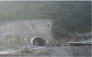
|
| Figure 1. Left tunnel entrance |
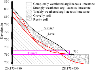
|
| Figure 2. Geological profile of the tunnel entrance |
Pre-supports were implemented to enhance the mechanical properties of the surrounding rocks and mitigate the impact of the landslide. Surface grouting was carried out to improve the quality of the surrounding rock at the entrance of the landslide. Figure 3 shows the layout of surface grouting, which adopted a mm PVC plastic flower tube with staggered holes on the tube walls every 15 cm. The grouting slurry, consisting of 1:1 cement mortar, had a total grouting volume of 1014.0 m3. The grouting range extended 13.0 m horizontally from the tunnel's center line, both to the left and right. Longitudinally, it spanned from Chainage ZK177+618 to Chainage ZK173+558. The grouting depth was at least 3.0 m from the original surface to weakly weathered bedrock. The pipe roof provided strong support for the surrounding rock above the tunnel by using high-strength steel pipes around the arch, as shown in Figure 4. The pipes were 40 m long and made of mm hot-rolled seamless steel, with small holes arranged in a plum blossom pattern. The drilling and steel pipes were parallel to the centerline of the line, with an elevation angle of 1°~3° from the horizontal plane. The length of overlap for the pipe shed must be at least 2.0 m, with a circumferential spacing of 40 cm. The grouting slurry used for the pipe consisted of 1:1 cement mortar, with an initial grouting pressure of 0.5-1.0 MPa and a final grouting pressure of 2.0 MPa. Following completion of the grouting process, 30# cement mortar was added to increase the strength and stiffness of the steel pipe. The main purpose of the anti-slide pile was to prevent sliding, as shown in Figure 4. It was located on the outer side of the tunnel, 7.5 m away from the centreline, and had a length of 20.0 m and a square cross-section with sides of 2.0 m. The top of the anti-slide pile is flush with the excavation contour line of the tunnel.
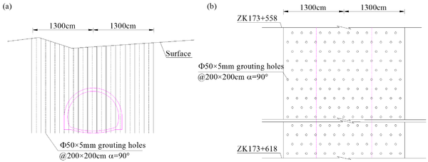
|
| Figure 3. Layout of surface grouting. (a) Vertical arrangement. (b) Horizontal arrangement |
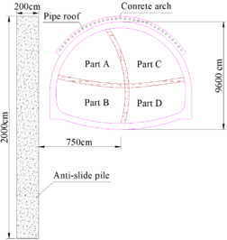
|
| Figure 4. Pipe roof, anti-slide pile and excavation method |
The rock surrounding the tunnel is Grade VI, which is extremely unstable. In addition, the tunnel entrance passes through a landslide, which can cause significant safety hazards such as surface settlement, collapse and landslide recovery during excavation. The middle partition method can be used to place support structures in the centre of the tunnel to provide additional support and protection, effectively controlling surface settlement and reducing the risk of rock collapse. The middle partition method involved the following sequence: (1) Part A is excavated first with temporary support in place. (2) Excavation of both Parts A and B simultaneously after excavating Part A for 2 m, with temporary support in place for both Part A and Part B. (3) Excavation of parts A, B, and C simultaneously after excavating parts B for 2 m, with temporary support in place for all three parts. (4) Excavation of parts A, B, C, and D simultaneously after excavating parts C for 2 m, with temporary support in place for all four parts. This excavation process continues in a cyclic manner, typically with each part being excavated in a sequence of 1 m at a time.
3. Numerical modeling
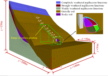
Figure 5 shows the three-dimensional model based on the terrain and geological characteristics of the tunnel. To ensure accurate results, the distance between the bottom of the model and the tunnel was three times the tunnel height, and the distance between the two sides of the model and the tunnel was five times the tunnel width, eliminating any boundary effects. The established model had a length of 200 m in the -direction, a width of 140 m in the -direction, and a height of 150 m in the -direction. It consisted of 645535 units and 112167 nodes. The boundary conditions were as follows: the three side boundaries at m, m, and m were fixed by roller, the bottom boundary was fixed by hinges, and the top surface was free. The side boundary with m was fixed by a roller from m to m, and from m to the top it was left free.
|
| Figure 5. Three-dimensional simulated model |
The solid elements were used to create the surrounding rocks, initial lining, pipe roof, anti-slide pile, and grouting area. The initial stress field only considered the self-weight stress field. The surrounding rocks and grouting area were modelled using the Mohr-Coulomb model, while the anti-slide pile, pipe roof, and initial lining were modelled using the elastic model. The parameters of the surrounding rock were obtained from engineering geological surveys and laboratory tests. Because the initial lining and pipe roof are both made of steel and concrete, the elastic modulus of both were calculated using the following equivalent equation [15-16]:
|
|
(1) |
where and are the elastic modulus and cross-sectional area of the concrete, respectively. and are the elastic modulus and the cross-sectional area of the steel arch, respectively. According to the Design Specification for Highway Tunnels (JTG D70-2018), the parameters of the surrounding rock in the surface grouting area have been increased by 30% to calculate the improvement effect of grouting on the strength and deformation characteristics of the rock. The calculated parameters are presented in Table 1. Based on the actual construction sequence, the first step was to apply a self-weight force field to the model. Following this, proceed with the construction of anti-skid piles, surface grouting, and pipe sheds in sequence. Finally, tunnel excavation and installation of initial support were carried out.
| Properties | (kg/m3) | (GPa) | (MPa) | (°) | (MPa) | |
|---|---|---|---|---|---|---|
| Completely weathered argillaceous limestone | 1800 | 0.50 | 0.38 | 0.10 | 20.30 | 0.54 |
| Strong weathered argillaceous limestone | 2300 | 2.28 | 0.35 | 0.25 | 22.20 | 0.98 |
| Weakly weathered argillaceous limestone | 2400 | 3.50 | 0.30 | 0.28 | 25.30 | 1.58 |
| Gravelly soil | 1700 | 0.10 | 0.22 | 0.06 | 15.22 | - |
| Rocky soil | 1800 | 0.15 | 0.15 | 0.08 | 18.75 | - |
| Pipe roof | 2450 | 65.60 | 0.26 | - | - | - |
| Anti-slide pile | 2500 | 32.50 | 0.20 | - | - | - |
| Initial lining | 2200 | 24.00 | 0.20 | - | - | - |
The simulation considered five different cases. Case I did not include any pre-supports, Case II only utilized anti-slide pile, Case III only employed surface grouting, Case IV solely installed pipe roofs, and Case V applied all three pre-supports. Nine points on the slope surface above the tunnel centerline (A1 to A9 in Figure 5, with a horizontal spacing of 10 m between adjacent points) were selected as key points. The displacement of each key point was evaluated under different cases to compare the reinforcement effect of different pre-supports on the landslide.
4. Results
4.1 Reinforcement effect of single pre-support on landslide
First, the reinforcement effect of a single pre-support is analysed. The deformation of the landslide mass after tunnel excavation under five cases is shown in Figure 6. Due to extremely unstable geological conditions, significant deformation and displacement occurs during tunnel excavation. At the same time, the tunnel excavation creates a free surface and the soil is subject to its own gravity, moving and deforming downwards. At the foot of the slope, the soil is subject to the greatest force of gravity. Therefore, in all cases, the greatest deformation occurs at the foot of the slope where the tunnel entrance is located, pointing to the lower right, and the downward deformation is slightly greater than the horizontal deformation. As the position moves upwards, the deformation becomes smaller and the direction tends to be more horizontal. The maximum displacement of the slope in the Case I reaches 15.1 cm, indicating that the entire landslide has undergone significant overall sliding and will be in an unsafe state without support. The maximum displacement of each landslide mass in Case II, III, IV and V is 14.3 cm, 9.8 cm, 8.9cm and 8.5cm, respectively, which is a decrease of 5.3%, 35.1%, 41.1% and 43.7% compared to the maximum displacement.
|
| Figure 6. Displacements of slope in different cases (unit: m) |
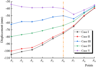
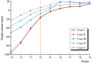
To further compare the effect of each pre-support, the displ acement of key points A1-A9 under different cases is plotted as shown in Figures 7 and 8. It is shown that after the application of the anti-slide pile, the horizontal and vertical displacements of key points A1-A9 decrease very little to the point of being negligible. The main reason for this is that the key points A1-A9 are located above the tunnel centerline, while the anti-slide pile was placed on one side of the tunnel, so the control of the landslide mass on the tunnel centerline is relatively weak. However, considering that this project is a segmented tunnel, and the subsequent excavation of the right tunnel may affect the left tunnel entrance, the main purpose of placing the anti-slide pile here was to resist the sliding force of the landslide mass by the strength of the anti-slide pile itself, thereby changing the stress state of the rock and improving the stability of the landslide.
|
| Figure 7. Horizontal displacements of key points A1-A9 in different cases |
|
| Figure 8. Vertical displacements of key points A1-A9 in different cases |
There are significant changes in each key point after construction of the surface grouting and pipe roof. The reduction in horizontal displacement after surface grouting is greater than that after pipe poof installation, and this difference is greatest at point A1. At the three key points A7, A8, and A9, the difference in the reduction of horizontal displacement between the two becomes very small. The reduction in vertical displacement at key points A1-A5 after the construction of the pipe roof is greater than that after surface grouting, and the difference is also the largest at point A1. At key points A6-A9, the reduction in vertical displacement after surface grouting is greater than that after pipe shed construction, but the difference between the two is very small. The varying reinforcement effects demonstrated by these two types of pre-supports are primarily attributed to distinct reinforcement mechanisms. The suppression of landslide deformation by the pipe roof is mainly due to two factors. Firstly, the pipe roof solidifies the surrounding rock mass of the tunnel through grouting, improving the mechanical properties of the surrounding rock mass and exerting a restraining force on the landslide mass, limiting its deformation and displacement. Secondly, the pipe roof itself has great stiffness, and the rigid structure can withstand the lateral pressure of the landslide mass, reducing the deformation and loosening of the landslide mass. Finally, the presence of a pipe roof can alter the contact area and contact mode between the landslide mass and the ground, resulting in a decrease in the frictional force between them. As the suppression effect in the horizontal direction is mainly transmitted through friction, the reduction of friction weakens the suppression effect of the pipe roof on the horizontal direction of the landslide mass. However, pipe roofs can only provide local constraint to the landslide mass and cannot comprehensively suppress the entire landslide. Since landslides are typically large systems, pipe roofs can only provide restraint within a limited range, thus their inhibitory effect on the horizontal direction of the entire landslide is limited. Surface grouting is a process that involves injecting high-strength cement mortar into soil and then chemically or physically reacting with the soil to increase its cohesion and internal friction angle. This improves its shear strength and sliding resistance. Additionally, the grouting mass fills gaps and cracks in the surrounding rocks, forming a dense consolidation body that increases the overall stiffness and strength of the surrounding rocks. Surface grouting controls lateral displacement by passing through vertical steel pipes and the entire landslide mass from the surface.
The horizontal displacement reduction of the three key points A7-A9 is not significantly different due to the surface grouting being applied for a total of 60 m in the direction of the tunnel. Similarly, the vertical displacement reduction of the five key points A5-A9 is not significantly different as the pipe shed was applied for 40 m. It is crucial to establish appropriate dimensions for the pipe shed and surface grouting range when dealing with landslide mass. Analysis of Case I reveals that pre-support is necessary to prevent significant horizontal displacement of key points A7-A9, while the vertical displacement of key points A5-A9 remains within a small range (<10mm). This demonstrates that the original pre-supports design of the reinforcement range for surface grouting and the length of the pipe roofs is reasonably appropriate.
4.2 Reinforcement effect of multiple pre-supports on landslide
Contrary to the deformation of the slope after a single pre-support, the maximum deformation of the slope in Case V (Figure 6) is located at the upper edge, outside the area of surface grouting and pipe shed reinforcement, with a value of approximately 5.5 cm (a decrease of 63.6% compared to Case I). The deformation at the entrance of the landslide is relatively small, indicating that the mass of the landslide was well controlled under the combined action of the three pre-supports.
The displacement changes of key points A1-A9 in Case V, as shown in Figures 7 and 8, are consistent with the variation patterns observed in other cases. However, the deformation values are smaller than those in other cases. To compare the effect of multiple pre-supports and single pre-support, the reduction rate of horizontal displacement of each key point in Cases II-V was calculated.
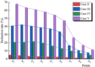
The results presented in Figure 9 illustrate that the reduction rate of horizontal displacement at each key point in Case V is basically equal to the sum of the corresponding reduction rates of horizontal displacement at key points in Cases II-IV. Specifically, the displacement reduction rate of key point A1 in Case V is 67.6%, while the displacement reduction rates in Cases II-IV are 4.8%, 40.8%, and 20.5%, respectively (the sum of which is 66.1%). The reinforcement effect of a single pre-support is not diminished when all three pre-supports are applied together. This is because the reinforcement mechanisms and scope of the three pre-supports are different, as discussed in section 4.1. Therefore, the effectiveness of a single pre-support is not reduced by multiple pre-supports.
|
| Figure 9. Reduction rate of horizontal displacement in Cases II-V |
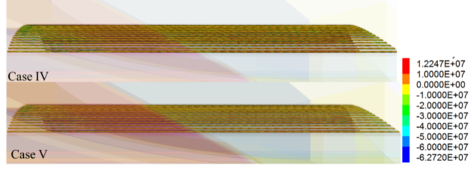
Figure 10 shows the maximum principal stress for Case IV, where only the pipe roof is applied, and Case V, where three pre-supports are constructed simultaneously. The stress distribution characteristics between the two cases are similar, with only numerical differences. The maximum principal stress for the pipe roof in Cases IV and V are 62.7 MPa and 47.6 MPa, respectively. The minimum principal stresses in these two cases are 12.2 MPa and 8.3 MPa, respectively. It is obvious that under the combined action of the three types of pre-supports, the stress it bears is less than that of the pipe roof support alone. This is due to the interaction of the three types of pre-supports in Case V. Although the pipe roof can only provide local constraint in a limited area around it, the surface grouting increases the overall stiffness and strength of the surrounding rock. In addition, the anti-slide piles also prevent the landslide from recovering to some extent. Under the combined effect of the three types of pre-supports, the excavation area will be more stable and the support structure will be safer.
|
| Figure 10. Maximum principal stress of pipe roof in Case IV and V (unit: Pa) |
4.3 Reinforcement effect of pre-supports on tunnel
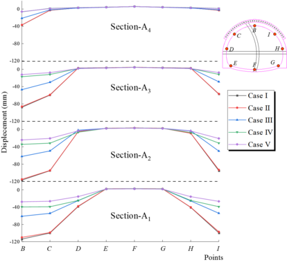
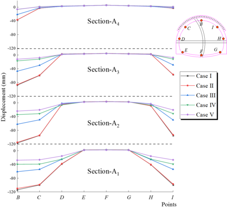
Take the key points B-F marked in Figure 11 and analyse the displacement changes of key points in different cases, where Sections 1-4 correspond to the sections of the tunnel where key points A1-A4 are located. There is almost no difference in the displacement of all key points in Cases I and II, indicating that the anti-slide pile has a relatively small control effect on the deformation of the tunnel structure. In the arch area (Key points B, C and I), the displacement of the key points shows a consistent pattern in all cross sections. The displacement of key points in Cases III, IV and V is highest in Cases III and lowest in Cases V, and these values are significantly smaller than in Cases I. This indicates that pre-supports can significantly improve the deformation of the rock surrounding the arch throughout the tunnel excavation process, and that the effect of the pipe roof is better than that of surface grouting. In the side wall area of the tunnel (Key points D and H), pre-supports still have a good deformation control effect in the entrance area. For example, in Section A1 the displacement was reduced by 35.4%, 35.9% and 59.6% in Cases III, IV and V. However, in Sections A2-A4, the effect of pre-support is not significant. Due to the fact that the tunnel in this paper is mainly affected by shallow burial and landslides, the deformation of the bottom area (Key points E, F and G) is very small even without pre-support (Cases I), so that targeted pre-supports are not necessary.
|
| Figure 11. Displacement diagram of key points in tunnel section under different working conditions (unit: mm) |
Along the direction of the tunnel axis, it can be seen that the deformation of all key points in Sections A1-A4 has decreased, especially in areas of large deformation such as arches and side walls. For example, the displacement of key point B in section 1-4 under condition 1 is 14.4 cm, 11.7 cm, 8.8 cm and 3.7 cm respectively, and the displacement in section 1-4 under condition 4 is 4.0 cm, 3.4 cm, 1.7 cm and 0.65 cm respectively. This indicates that the deformation of the tunnel structure is maximum in the early stages of excavation and that the tunnel becomes increasingly stable as excavation progresses.
5. Conclusions
(1) Under the condition that only a single pre-support was used, the reinforcing range of the anti-slide pile was relatively small. The reduction in horizontal displacement caused by surface grouting was significant, particularly at the tunnel entrance, where displacement was reduced by up to 40%; although the reduction in vertical displacement was greatest for the pipe roof, the difference was not significant compared to surface grouting, using the pipe roof and surface grouting pre-support measures, the maximum vertical displacement was reduced by 40% and 10% respectively.
(2) Due to the different objectives of the three types of pre-supports, as well as the different reinforcement principles and area, good results were achieved in the combined application. In the case of multiple pre-supports constructed, the horizontal displacement reduction rate of each key point was basically equal to the sum of the corresponding horizontal displacement reduction rates of the key points under a single pre-support. In addition, the use of multiple pre-supports can reduce the stress on the structure caused by a single pre-support, making the structure safer.
(3) Pre-support can significantly improve the deformation of rocks around the arch, and the effect of pipe roof was better than that of surface grouting. However, the effect of anti-slide piles has only a minimal improvement effect during excavation in the A1 plane. In the sidewall area, surface grouting and pipe roof still had good deformation control effect in the entrance area, but the effect will gradually decrease as excavation progresses. However, the anti-slide piles did not show any improvement in the sidewall area.
(4) Along the direction of the tunnel axis, the deformation of the tunnel structure had decreased, especially in areas of significant deformation such as the arch crown and side wall. This indicates that tunnel deformation is greatest in the early stages of excavation, and that the tunnel becomes increasingly stable as excavation processes.
(5) In loose and unstable slope deposits, it is necessary to use surface grouting when entering the tunnel, and the pipe shed can further enhance its arching ability. However, the pre-supports of the pipe roof do not significantly improve the suppression of the deformation of the tunnel sidewalls and the bottom of the vault.
References
[1] Adam D., Markiewicz R., Brunner M., Block-in-matrix structure and creeping slope: tunneling in hard soil and/or weak rock. Geotechnical & Geological Engineering, 32:1467–1476, 2014.
[2] Zhang Q., Wang J., Wang W., et al. Study on slope stability due to the influence of excavation of the high-speed rail tunnel. Geomatics, Natural Hazards Risk, 10(1):1193–1208, 2019.
[3] Qin Y.W., Chen Y.H., Lai J.X., et al. Failures in loess slope-tunnel system: An overview of trigging sources, acting mechanism and mitigation strategies. Engineering Failure Analysis, 158, 107996, 2024.
[4] Chen H., Lai H.P., Huang M., et al. Failure mechanism and treatment measures of supporting structures at the portal for a shallow buried and asymmetrically loaded tunnel with small clear-distance. Natural Hazards, 114(2):2283–2310, 2022.
[5] Guo J.C., Li C., Analysis of the construction plan for entering the mountain tunnel (in Chinese). Railway Engineering, (10):32–34, 2004.
[6] Wang H.T., Jia J.Q., Kang H.G. Analytical approach and field monitoring for mechanical behaviors of pipe roof reinforcement. Journal of Central South University of Technology, 16(5):827–834, 2009.
[7] Bao L.L., Wei F. Tunnel construction in shallow soft rock using the pipe shed support. Scientific Reports, 14(1):3401–3401, 2024.
[8] Shi Y.F., Zhang T., Cao C.W., et al. Study on the mechanism of tunnel subhorizontal jet grouting reinforcement based on a shell model on two-parameter foundation. Journal of Engineering Mechanics, 150(4), 2024.
[9] Cai M., Xu H., Han F.Q., et al. Analysis and field monitoring on surface high pressure jet grouting reinforcement in shallow-buried tunnel section. Journal of Highway and Transportation Research and Development, 40(01):152–159, 2023.
[10] Xiao J.Z., Dai F.C., Wei Y.Q., et al. Analysis of mechanical behavior in a pipe roof during excavation of a shallow bias tunnel in loose deposits. Environ. Earth Sci, 75(4), 293, 2016.
[11] Ibtissem S., Mustapha A., Panagiotis S. Effect of the umbrella arch technique modelled as a homogenized area above a cross passage. Applied Sciences, 13(3):1588–1588, 2023.
[12] Ying H.F., Wang L.Y., Ye H., et al Layout optimization of advance reinforcement of soft rock tunnel and stratum mechanical response (in Chinese). Highway, 67(06):378–385, 2022.
[13] Xu J.S., Xu H., Zhang H.T., et al. Reinforcement mechanism and parameter analysis of horizontal high-pressure rotary jet grouting piles for Tertiary semi-diagenetic water-rich sandstone tunnel (in Chinese). Chinese Journal of Geotechnical Engineering, 1-10, 2024.
[14] JTG D70-2018. Specifications for design of highway tunnels: Section 1 Civil Engineering (in Chinese). China Communication Press, Beijing, 91–96, 2018.
[15] Tang J,S., Liu S,Y., Tong L,Y. The minimum safe net dis-tance between large span expressway tunnels (in Chinese). China Civ. Eng., 41(12):79–84, 2008.
[16] Xiao J.Z., Dai F.C., Wei Y.Q., et al. Cracking mechanism of secondary lining for a shallow and asymmetrically-loaded tunnel in loose deposits. Tunnelling Underground Space Technol., 43(7):232–240, 2014.Document information
Published on 12/06/24
Accepted on 27/05/24
Submitted on 14/04/24
Volume 40, Issue 2, 2024
DOI: 10.23967/j.rimni.2024.05.013
Licence: CC BY-NC-SA license
Share this document
Keywords
claim authorship
Are you one of the authors of this document?