(Created page with "<!-- metadata commented in wiki content <div class="center" style="width: auto; margin-left: auto; margin-right: auto;"> <big>In-situ polymerizable thermoplastic and bio-epo...") |
m (Akshay.hejjaji moved page Draft Hejjaji 505280600 to Bhatia et al 2024b) |
(No difference)
| |
Latest revision as of 17:20, 4 June 2024
Abstract
This study evaluates various quasi-static mechanical properties of an in-situ polymerizable thermoplastic and a bio-based thermosetting composite comprising of non-crimp fabric reinforcement for potential use in the next generation of Offshore Wind and Tidal Power platforms. Mechanical properties are characterized under tensile, flexural, in-plane shear and interlaminar shear loading. Results reveal that the evaluated properties differ based upon matrix type. Fractographic evidence from scanning electron microscopy is used to explain the differences observed and was generally consistent in terms of revealing cohesive failure at the fiber-matrix interface for the thermoplastic composite and contrasting adhesive failure for the thermosetting composite. For glass fibre reinforcement, the thermoplastic composite is superior in terms of flexural 90° properties (+20%) while the thermosetting composite performed better in flexure 0° in terms of both strength (+15%) and modulus (+25%). In terms of interlaminar shear, the thermosetting composite exhibited higher strength (+14%) while Tensile and in-plane shear properties are similar for composites of both resin systems. Overall, neither matrix is superior in terms of overall mechanical properties and both matrices show promise as a stepping stone towards the use of more sustainable constituents in offshore structures.
Highlights
- Quasi-static mechanical performance and failure analysis of relatively sustainable composites are presented.
- Failure analysis indicate cohesive failure of the thermoplastic based composite and interfacial failure of the thermosetting based composite.
- Proposed resins are benchmarked against the composites manufactured using conventional resins.
- Overall, both matrices show promise as a stepping stone towards more sustainable offshore structures.
Keywords: Vacuum Assisted Resin Infusion (VARI), Infusible thermoplastic (Elium®), Bio-based epoxy, Mechanical characterization, Offshore renewable energy.
1. Introduction
Offshore wind and tidal energy are considered as a major source of sustainable and clean renewable energy having huge potential to be harnessed globally. Offshore wind farms (OWF) and tidal energy farms have no direct emissions during energy production resulting in sustainable power generation and there is an increasing trend of OWFs being installed globally [1,2]. However, the cost of generating energy is still significantly higher than conventional methods owing to the high installation and maintenance costs. According to Mukherjee et al., up to 90% of the total offshore wind turbine installation mass is a result of the use of steel [3]. This results in high maintenance costs mainly arising due to corrosion and fatigue exacerbated by the harsh marine environment. According to Orlikowski et al., the corrosion rate of carbon steel at a depth of 50 m is 0.8 mm per year [4]. This greatly impacts the structural integrity of these structures. In fact, the operation and maintenance costs add up to 25-35% of the total lifetime costs. Indeed, 60% of the maintenance costs for these offshore wind turbine structures comes from the repair and preventive maintenance due to the corrosion of steel [5,6]. At present, the supporting structural elements of wind turbines employ steel, and the blades employ composite materials for their construction [7]. The ongoing effort under the EU H2020 FIBREGY project is to replace the steel used in the structural elements of floating wind turbines/tidal turbines with composite materials, thus exploiting the benefits of composite materials in terms of immunity to corrosion and improved fatigue performance thereby significantly reducing maintenance costs leading to more affordable clean energy.
Though composite materials provide an attractive replacement to steel, their production and end-of-life disposal is not sustainable owing to the use of petroleum-based resins reinforced with synthetic fibres. The end-of-life (EOL) disposal of such composite materials has a negative environmental impact, as the materials are predominately disposed in landfill compromising the ideology of environmentally conscious energy production. In order to reduce the environmental impact, there is an increasing ambition to develop composite materials which are more environmentally friendly, while at the same time satisfy the structural and functional requirements for offshore installations. The primary requirements for composite materials employed in offshore structures are high immunity to hygrothermal effects, high stiffness, strength and good fatigue performance. Furthermore, the composite material shall be processable at close to ambient conditions using the vacuum assisted liquid resin infusion technique, which is best suited for the manufacture of large-scale composite structures. In the current work, the focus is on the identification, manufacture and characterization of relatively sustainable fiber reinforced composite materials systems to be employed in offshore wind and tidal energy structures.
Regarding fibre reinforcements, the most environment friendly options are in the form of natural fibres having plant or mineral based origins such as flax, jute etc. However, various studies have reported inferior material properties and reduced stability of natural fibre laminates when exposed to moisture and ultraviolet (UV) radiation [8–13]. This is particularly challenging in the case of offshore energy applications where such exposure is predominant. Liu et al. studied the mechanical properties of composites made of flax and glass fibres including a flax-glass hybrid material [13]. It was reported that the flax composite exhibited inferior properties compared to the glass composite and the properties of the flax fiber composite deteriorated when exposed to moisture. To counter this, hybrid flax-glass composites were tested, which again exhibited inferior performance after exposure to moisture. Therefore, even though natural fibres have good sustainability credentials, their inferior mechanical properties (particularly stiffness) and poor moisture resistance compared to synthetic fibres like glass or carbon render them an unsuitable choice of reinforcement for composite structures exposed to harsh marine environments at their current stage of development. For this reason, glass and carbon fibre reinforced laminates are the focus of the current study. However, relatively sustainable matrices such as the bio-epoxy and the in-situ polymerisable thermoplastic are potentially viable options at their current stage of development.
Another direction for improving the sustainability of composite materials is to identify more environmentally friendly matrix systems. Several researchers have demonstrated the manufacturing of composite materials using thermoset resins derived from plant-based sources like vegetable oils by processes such as acrylation and epoxidization (eg. Acrylated epoxidized soybean oil) [14–16]. These plant based (Vegetable oil) epoxy resins appear like suitable candidates in terms of their relatively low environmental impact. However, vegetable oil-based resins exhibit high viscosity and low cross-linking density due to the long chain fatty acids present in the oils both of which are undesirable [14,16]. High viscosity makes these resins unsuitable for vacuum assisted liquid resin infusion and ambient temperature processing. Additionally, they require toxic petroleum-based curing agents like anhydrides, isocyanates or styrene. In addition, the major concern that deters the use of natural resin or natural fiber composites is their inferior mechanical properties and loss of strength when exposed to moisture (up to 50%) compared to commercially available resins [9–12,16]. Alternatively, bio-based thermosetting resins where a percentage of the constituents required to synthesise the resin is derived from plant sources are a potential candidate which also have a low environmental impact. In a recent study, Terry et al. compared nine commercially available bio-based resin systems in the neat condition (no reinforcement) [17]. Considering the requirements of sustainability, low viscosity and ambient temperature curing, InfuGreen® 810, produced from 38 % of carbon from plant origin coupled with SD 8824 hardener was one of the most promising bio-epoxy systems and compared well to conventional epoxies, possessing good strength, stiffness, toughness and a reasonable glass transition temperature [17,18]. The resin has low viscosity at ambient temperature which enables manufacturing by vacuum assisted liquid resin infusion processes making it suitable for the manufacture of very large components including relatively thick laminates. Hence, InfuGreen® 810 with SD 8824 hardener was selected for evaluation in the current study.
Another approach to produce more sustainable composites is to use thermoplastics. Unlike thermosets, thermoplastics can be recovered and repurposed/recycled at the end-of-life thereby supporting a circular economy by preventing disposal of components into landfill at end-of-life. However, a major challenge with thermoplastics are the processing requirements, which include relatively high temperatures (> 100° C) and pressures (≥7 Bar) [19]. Achieving these process parameters when manufacturing large structural components of OWTP is not considered economically viable. However, Elium® a relatively new acrylic based in-situ polymerizable resin is an infusible thermoplastic that fulfils the criteria of low viscosity and can be infused under vacuum at room temperature and post cured at a relatively low temperature i.e. below 60° C. Regarding the recyclability aspect several researchers, Cousins et al. and demonstrated the economic feasibility of recycling Elium® based glass fibre composites using dissolution process [20]. Additionally, Gebhardt et al. have demonstrated closed recycling loop for Elium® CFRP laminates, recycling waste matrix material directly back into the composite manufacturing process [56]. Apart from recycling, Elium® being a thermoplastic allows for reshaping for reuse [57], repair with liquid resin injection [58] or thermal consolidation [59]. Thus, Elium® presents an attractive option for infusing large scale wind turbine structures and therefore is chosen for evaluation in this study.
A detailed mechanical characterization of composites made from these relatively sustainable matrix material options is the first step to realize their benefits for use in OWTPs. There are various studies in the literature which have investigated the mechanical response of Elium® based [21–31,57,60,61] and InfuGreen® [32,33] based composites. However, no single work comprehensively covers all the basic static mechanical behaviour characterization and the data is incomplete, especially for quasi-unidirectional non-crimp glass and carbon fibre reinforced composites.
Overall, the authors are not aware of any published work available in the open literature providing a comprehensive characterization of in-situ polymerizable thermoplastic (Elium) and bio-based epoxy (InfuGreen® 810) based composites under various loading configurations. The current work addresses these aspects, investigates the damage mechanisms involved and benchmarks the results against traditional epoxy-based laminates reported in the literature. This provides a ready data set for environmentally conscious material selection and is a prerequisite for the development of numerical models necessary for the optimum design of OWTP structures.
2. Materials and Methods
- 2.1. Materials and Specimen preparation
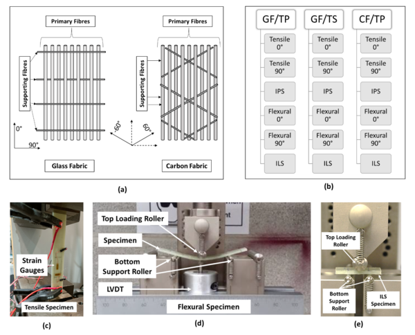
Glass and carbon fiber composites were manufactured using a thermoset (TS or InfuGreen®) and two different grades of thermoplastic (TP or Elium®), one which is compatible with glass fibre-based reinforcement (Elium® 188 XO) and another which is compatible with carbon fibre-based reinforcement (Elium® 188 O). The detailed technical specifications of the resin systems are summarised in Table 1. Laminates were manufactured using E-glass fibre (GF) from NEG and carbon fibre (CF) from Mitsubishi. Both fibres were in a non-crimp-fabric format of areal density 1182 g/m2 and 438 g/m2 respectively with a quasi-unidirectional lay-up. A schematic representation of the structure of the fabrics employed is presented in Fig. 1(a). The E-glass fabric is made up of glass fibres orientated in the warp direction (96%) and secondary glass fibres orientated in the weft direction (3%). The carbon fabric consists of carbon fibres orientated in the warp direction (93%) and also glass fibres (3.6%) orientated at ±60° to the 0° fibre direction. These additional glass fibres stabilize the fabric and aid in handling and storage. In addition to the glass and carbon fibres, polyester yarn (amounting to ≈ 1 % in Glass fabric and ≈ 2-3 % in carbon fabric) is used for stitching for the purpose of stabilising the fabric. The various lay-ups and materials are presented in Table 2. The vacuum assisted liquid resin infusion technique was employed to prepare the laminates which were allowed to cure at ambient temperature in accordance with the parameters specified in Table 1. Test specimens were then extracted by using abrasive water jet cutting. Post curing was performed on the test specimens post extraction as per details provided in Table 1.
| Thermoplastic Acrylic (TP) (Arkema) |
Thermosetting (TS) Bioepoxy (Sicomin) | ||
| Name | Elium 188XO | Elium 188O | SR InfuGreen 810 |
| Curing Agent | BP-40-SAQ (Liquid) | BP-50-FT (Powder) | SD 8824
(Liquid) |
| Mass Ratio (Resin : Curing Agent) |
100 : 3 | 100:3 | 100 : 22 |
| Viscosity | 100 mPa.s at 25°C | 100 mPa.s at 25°C | 120-320 mPa.s at 25°C |
| Curing time at ambient | 24 hr | 24 hr | 16 hr |
| Post-cure temperature | 60 °C | 60°C | 60 °C |
| Post-cure time | 24 h | 24h | 16 h |
| Storage Life | 6 months | 6 months | 24 months |
| Tensile Strength | 56 MPa | 56 MPa | 65 MPa |
| Tensile Modulus | 2.6 GPa | 2.6 GPa | 2.8 GPa |
| Lay-up | Reinforcement | Resin | Initiator | |
| GF/TP | [±45]2S | BP-40-SAQ | ||
| [0]2S | U-E 1182 g/m2 | Elium 188 XO | ||
| [90]2S | ||||
| GF/TS | [±45]2S | SD 8824
| ||
| [0]2S | U-E 1182 g/m2 | SR InfuGreen 810 | ||
| [90]2S | ||||
| CF/TP | [±45]4S | BP-50-FT | ||
| [0]2S | U-C 438 g/m2 | Elium 188 O | ||
| [90]2S, [90]4S |
- '2.2.' Test Methodology
A summary of all the tests conducted and the evaluated properties is presented in flowchart in Fig. 1(b) and the corresponding characterized properties are tabulated in Table 3. Fibre volume fraction (Vf) was determined for the fibre dominant [0]NS laminates and the properties determined were normalized to a Vf of 55% for uniformity in property comparison across laminate configurations for fibre dominant [0]NS lay-ups. The fracture zones of tested specimens were further investigated using a Hitachi SU-70 high-resolution scanning electron microscope (SEM). Energy Dispersive X-ray spectroscopy (EDX) was also performed on a few selected specimens using an EDX attachment (Oxford Instruments) to understand the elemental composition remaining on the fibers post fracture. For performing EDX analysis, an excitation voltage of 20 kV was used for all specimens.
| Test Method | Test Standard | Properties | Lay-up |
| Tensile | ISO 527 [38] | 11, E11, ν12 | [0]2S |
| 22, E22, ν21 | [90]2S | ||
| In-plane-shear | ISO 14129 [39] | , | [±45]2S |
| Flexure 3-pt bend | ISO 14125 [40] | , E11 | [0]2S |
| , E22 | [90]2S | ||
| Interlaminar Shear | ISO 14130 [41] | [0]2S |
Notations:
- 2.3 Test Procedures
Tensile (0˚ and 90˚) and In-plane Shear (IPS): Tensile (0˚ and 90˚) and IPS (±45˚) specimens were tested in accordance with ISO 527 [38] and ISO 14129 [39] test standards, respectively. The test coupons were sized to 25 mm in width and 150 mm in gauge length where the nominal thickness of GF/TP and GF/TS was 3 mm and that of CF/TP was 1.8 mm. All the specimens were tested under displacement control at 2 mm/min. Strain gauges were employed to measure the axial/longitudinal (0˚) and transverse (90˚) strains. The modulus (for both Tensile 0˚ and 90˚) was calculated for a longitudinal strain range of 0.0005- 0.0015 and the shear modulus (for IPS) was calculated for a shear strain range of 0.001-0.005. Fig. 1 (c) depicts the experimental setup used to conduct Tensile and IPS tests. The strength/load at failure and the strain at failure are reported at the point of initiation of the failure in the specimen identified by the first load drop in mechanical response curve (for Tensile) and/or corresponding to 5% strain for IPS specimens.
Flexural (0˚ and 90˚): Flexure specimens were tested in a three-point-bending loading mode in accordance with ISO 14125 [40]. The span-to-thickness ratio for GF/TP and GF/TS test coupons was 20:1 with nominal thickness of 3 mm and width of 15 mm. CF/TP test coupons had a nominal thickness of 1.8 mm and 15 mm width were sized to obtain a span-to-thickness ratio of 40:1. The tests were conducted under displacement control conditions at a rate of 1 mm/min. A displacement transducer was used to record specimen deflection during testing for flexural 0˚ specimens. In the case of flexural 90˚ specimens, instrument cross-head movement was used to record specimen deflection. The roller diameters of the load nose and support points were 10 mm and 4 mm respectively. Fig. 1 (d) depicts the experimental setup used to conduct flexural tests. The strength/load at failure and the strain at failure are reported at the point of initiation of the failure in the specimen identified by the first load drop in the mechanical response curve. The modulus (for both flexural 0˚ and 90˚) was calculated for a longitudinal strain range of 0.0005- 0.0025.
Interlaminar Shear (ILS): Interlaminar shear specimens were tested in a three-point-bending loading mode under displacement control conditions at a rate of 1 mm/min in accordance with ISO 14130 [41]. The span-to-thickness ratio for GF/TP and GF/TS test coupons was 5:1 with nominal thickness of 3 mm. Whereas CF/TP test coupons with 1.8 mm thickness were sized to obtain a span-to-thickness ratio 5.5:1. Fig. 1 (d) depicts the experimental setup used to conduct ILS tests. The roller diameters at the load nose and support points were 10 mm and 4 mm, respectively.
3. Results and Discussions
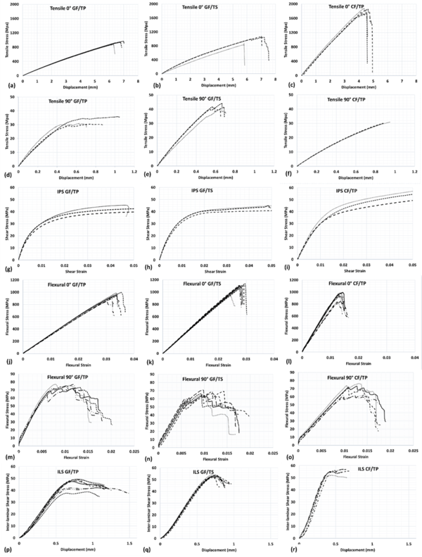
Typical load response curves for all the laminate and loading configurations are presented in Fig. 2 and the characterized mechanical properties are summarised in Table 4. Response of laminates under each loading condition is discussed in sections 3.1 to 3.4 followed by fractography analysis. The obtained properties are also benchmarked against conventional composites from literature.
| Test Method | Properties | GF/TP | GF/TS | CF/TP |
| Tensile 0˚ |
E11 ν12 |
|
|
106.2 (6.3) 117.9*
|
| Tensile 90˚ | 22
E22 ν21 |
13.6 (0.4) (0.004) |
(0.002) |
(0.003) |
| In-plane-shear |
|
|
|
|
| Flexure 0˚ |
E11 |
|
|
|
| Flexure 90˚ |
E22 |
|
|
6 |
| Interlaminar Shear |
Note- *Normalised values with respect to 55% fibre volume fraction.
Standard deviation values are in parenthesis.
Notations:
3.1 Tensile (0˚ & 90˚) behaviour
Figure 2 (a) to (c) present the stress-displacement curves for the 0˚ specimens under tensile loading. It is evident that the specimens for all three composite types exhibit a linear response. The tensile strength ( in Table 4) of GF/TP and GF/TS is quite similar whereas CF/TP clearly exhibits a much higher strength as expected. A similar trend is evident for the modulus of elasticity. The failed specimens were further examined to understand the failure mechanisms (refer Fig. 3. (a)-(c)). In unidirectional composites, typical failure modes include fibre splitting due to matrix shear and fibre breakage [42,43]. In the present study, it is observed that all the 0˚ specimens failed primarily due to fibre breakage and fibre splitting in the laminate with the splits orientated parallel to the loading direction. This failure mode occurred with a sudden abrupt drop in load as observed from the mechanical response plots shown in Fig. 2 (a)-(c). The observations indicate a fibre dominant failure process and marginal influence of the matrix on the damage modes as expected.
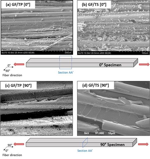
However, in the case of Tensile 90˚ specimens, it is observed that the GF/TP and GF/TS specimens exhibit significantly different strength (refer Table 4) even though ultimate failure was very similar in the form of matrix cracking in a direction transverse to the loading direction (refer Fig. 3(d)- (f)). A comparison of the mechanical response (see Fig. 2 (d)-(e)) for GF/TP and GF/TS specimens shows the difference in behaviour observed. GF/TP specimens exhibit lower strength and greater ductility-to-failure in comparison to that of GF/TS specimens. The ductile behaviour and lower strength of the TP composite suggest that the matrix close to the fibre surface failed first before the fibre-matrix interface. In the case of the TS composite, the relatively high strength and minimal ductility evident from the stress-displacement curve suggests that the matrix is stronger than the fibre-interface in this material system and this caused failure to first occur at the fibre-matrix interface rather than in the matrix remote from the fibre. To support these observations, fractography analysis of selected specimens was performed. The fracture surface characteristics relating to both resins were indeed observed to be different. Fig. 4 presents SEM images taken from the fracture surfaces of the Tensile (0˚ & 90˚) specimens. Inspection of the SEM images reveal evidence that the matrix is still adhered to the fibre surface in the case of GF/TP specimens post testing. In the case of GF/TS specimens, a relatively cleaner fibre surface is evident. This evidence strongly suggests that the TS composite failed at the fibre-matrix interface while the TP composite failed in the matrix remote from the fibre-matrix interface which explains the difference in behaviour observed in Fig. 2(d) (GF/TP) and 2(e) (GF/TS). In fact, it is evident from Fig. 4(c) that a layer of matrix is present on the fibers along with river marks which indicates microductility and explains the high strain to failure observed in Fig. 2(d).
Regarding modulus, it must be noted that for the glass fabric used in this study, close to 3% of the fibres are orientated in the weft direction (refer Fig. 1). In tensile 90˚ specimens, these supporting weft fibres oriented parallel to the direction of loading significantly contribute to the modulus (measured in the initial stage of the test) which explains the higher modulus measured (13.6-14 GPa) compared to the modulus of the bulk resin (3.17 GPa). The GF based 90˚ specimens exhibit a higher modulus (13.6-14 GPa) compared to CF/TP 90˚ specimens (7.4 GPa) since in the latter, fibres are not present in the loading direction as the supporting fibres (3.6%) are oriented at ± 60˚ with respect to the loading direction.
3.2 IPS behaviour
Figure 2 (g) to (i) show the stress-strain response of the IPS specimens. The three laminates were seen to exhibit similar values of in-plane shear modulus (Table 4). The shear modulus is calculated over a strain range (0.001-0.005) which is at the very initial stage of the test in order to capture the matrix behaviour and eliminate the effect of extensive fibre reorientation due to loading. Researchers have indicated that rotation of the fibres towards the longitudinal direction can produce a strengthening effect [44,45]. The deviation in shear modulus observed across the laminates is under 10%. A comparison between GF/TP and GF/TS also reveals a negligible difference in the shear strength considering the different matrix systems employed. However, for the same type of resin (thermoplastic-Elium), the shear strength is seen to be significantly higher for CF/TP at 0.05 shear strain compared to GF/TP. It is possible that the weave architecture in the case of carbon fabric particularly the presence of fibres in the ±60˚ direction may have contributed to the strengthening effect leading to higher shear strength in CF/TP specimens comparatively. Evidence for this can be sourced from the stress-strain curve for CF/TP (Fig. 2 (i)) where a significant positive slope occurs after 0.01 strain compared to GF/TP which exhibits a less positive slope (Fig. 2 (g)).
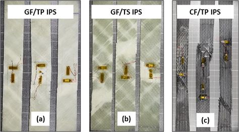
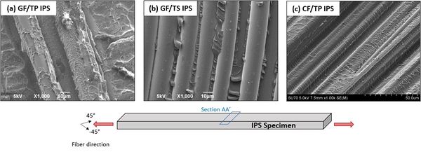
An inspection of the tested specimens reveals multiple dispersed failure initiation zones in the specimens occur at an angle of 45˚ with respect to the loading direction (Fig. 5). The formation of shear bands was distinctly observed for all of the tested composites similar to other studies [44]. The SEM images of the fractured specimens (Fig. 6.) reveal cleaner fibre surfaces in GF/TS as compared to the fibre surfaces present in GF/TP and CF/TP. This is consistent with the observations gathered from tensile 0˚ and 90˚ test specimens.
In addition to analysing the SEM images, EDX analysis was also performed on the fracture surfaces of the IPS test specimens. The specimens for EDX were drawn from GF/TP and GF/TS composites. An assessment of elemental composition gleaned from the fibre surfaces from the two composites revealed the presence of larger percentages of Silicon and comparatively lower values of carbon on the fibre surfaces in the case of GF/TS composites as compared to GF/TP composites. This validates the SEM observation that in the case of GF/TS there are virtually no traces of resin on the fiber (cf. Fig 6). Based on this, it can be concluded that, the TP predominantly undergoes cohesive failure at the fiber-matrix interface while the TS predominantly experiences adhesive failure. This also means that the shear strength of the TP resin is lower than the fiber-matrix interfacial strength (for both GF/TP & CF/TP), hence a cohesive failure occurs. In the case of GF/TS, the shear strength of TS is higher than the fiber-matrix interface strength hence a failure at the fibre-matrix interface is seen (clean fibers post failure, cf. Fig. 6b).
'3.3' Flexural behaviour
Fig. 2 (j)-(l) show the stress-strain behaviour of 0˚ flexural specimens. Referring to Table 4, the highest normalized flexural strength and modulus as expected is observed for the 0˚ CF/TP specimens (≈23 % higher strength and ≈3 times higher modulus as compared to GF/TP) which is predominantly due to the higher strength and stiffness of carbon fibres as compared to those of glass fibres. A comparison of GF/TP and GF/TS in terms of normalised strength and modulus reveals that the TS specimens exhibit higher flexural strength (+15%) and modulus (+25%) than TP based specimen. The difference in strength is consistent with the trend of the 90˚ tensile results and can also be explained by the different locations where failure initiates viz. in the matrix for the thermoplastic and at the fibre-matrix interface for the thermoset as shown by SEM. Additionally, the crosslinking of polymer chains in the thermoset matrix potentially provides greater interlaminar shear stiffness in the resin rich interlaminar region between plies leading to greater resistance to bending compared to the amorphous thermoplastic which may be more compliant in terms of interlaminar shear stiffness due to the lack of crosslinking. The slightly higher in-plane shear modulus of GF/TS also supports this suggestion.
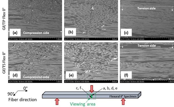
The ultimate failure under bending occurs in the form of significant fibre kinking on the compression side resulting in a sudden drop in load as can be seen in the mechanical response curves Fig. 2 (j)-(l). Fig. 7 (a) to (c) includes the post-test specimen images and Fig. 8 shows SEM images indicating the failure modes in 0˚ specimens. There is evidence of fibre kinking in the first and second ply at the centre of the specimen just beneath the load nose. The kinking is seen to progress from first ply to second ply with increasing load. Damage was localized to the first few plies with no visible damage on the tensile side of the specimens as seen in Fig. 8(c) and Fig. 8(f). Therefore, the failure mode for the flexure 0˚ specimens is predominantly governed by the mechanisms occurring on the compression side under the load nose.
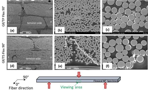
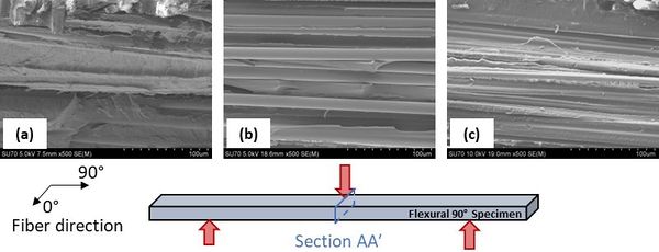
Fig. 2 (m)-(o) show the flexural response of the 90˚ specimens. It is observed that the drop in load is relatively gradual in these cases indicating matrix crack progression with increase in load. A comparison of GF/TP and GF/TS specimens reveals a difference in the strength values obtained. It is to be noted that, the load considered to calculate failure strength is the load at which the first drop in load was seen. In the case of GF/TS this first drop in load is significantly lower than the final failure which leads to lower strength values. Unlike the TS, the TP shows ductile behaviour which delays the first failure and hence the load drop is seen closer to final failure. The specimens after failure are shown in Fig. 7 (d) to (f). SEM analysis of failed flexural 90˚ specimens (refer Fig. 9) reveal the formation and propagation of cracks along the interface between the fibres and the matrix. This indicates that the failure process controlling the behaviour of the 90˚ specimens is interfacial cracking beneath the loading nose Fig. 7(d) to (f) on the tensile side with the crack propagating perpendicular to the normal stresses as observed in Fig 9. SEM analysis of the fracture surface of flexural 90˚ specimens (Fig. 10) revealed a cleaner fibre surface for GF/TS specimen as compared to the GF/ TP specimen strongly suggesting that the failure in the TP composite is cohesive at the fibre matrix interface while adhesive failure dominates in the TS composite consistent with previous observations for other loading modes.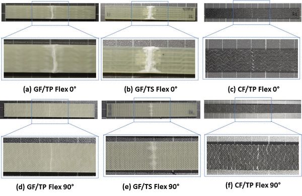
'3.4' Interlaminar shear behaviour
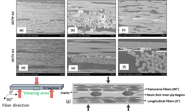
Short beam shear tests were performed on the specimens to determine the Interlaminar shear strength (ILSS) (Cf. Table 4). The post-test images of the specimens are presented in Fig. 11 and clearly show the shear bands resulting from interlaminar shear failure. Material damage on either side beneath the loading nose is also visible and is possibly due to the stress concentration beneath the loading nose resulting in localised fibre breakage. ILSS for GF/TS specimens is about 16% higher than that of GF/TP specimens. This is due to the crosslinking mechanism present in thermoset matrix for GF/TS. The cross linked polymer chains result in network structures which improves the overall matrix mechanical properties of the thermoset including shear behaviour. However, CF/TP specimens exhibit higher ILS strength (≈20%) in comparison to the GF/TP composite. Though it is the similar matrix material this difference arises due to the different architectures of the GF and CF fabrics used in this study. Regarding the glass fibre fabric used, 3% (by GSM) transverse fibres are present which causes an early initiation of cracks. However, the CF fabric has no transverse fibres (cf Fig.1). The evidence for this can be found in the SEM analysis where cracking was observed near the mid-plane of the GF specimens close to the region of theoretical maximum interlaminar shear (cf. Fig 12). The SEM images reveal the effect of fibre architecture on the location of initiation of failure within the specimen. In the case of GF/TP specimens, crack initiation was seen in the resin rich inter-ply region and in vicinity of 90˚ fibres. Additionally, the cracks propagated parallel to the span in the inter ply regions as shown in Fig. 12(a)-(c). Fig 12(g) presents a schematic of the premature failure mechanism arising due to the presence of transverse fibres in the GF based ILS specimens. For GF/TS specimens, it can be observed that the failure primarily initiates in the inter ply region in the central region of the specimen with a crack developing parallel to the span as seen in Fig. 12(d)-(f). Thus, it is inferred that the ILS strength is influenced by the type of resin (thermoset or thermoplastic), fiber-matrix interface characteristics and the fibre architecture (presence of transverse fibres) which governs the failure initiation and its location.
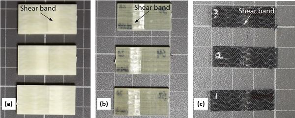
Fig. 11 Post testing specimen images depicting typical failure observed under ILS loading for (a) GF/TP (b) GF/TS (c) CF/TP specimen.
'3.5' Benchmarking of characterized properties
The average values of the properties characterised in this work are compared with data from the literature. In the case of tensile 0˚ specimens, GF/TS (895 MPa, 42.8 GPa) performed similar to GF/TP (811 MPa, 41 GPa) in the current work in terms of strength and modulus while CF/TP (1898 MPa, 117 GPa) exhibited much higher strength and modulus as expected. Data available in the literature for GF laminates (723-860 MPa, 35-40 GPa) and CF Laminates (1119 MPa, 58 GPa) exhibit strengths and moduli in a similar range [46–48].
Regarding tensile 90˚, a higher strength and a similar modulus were reported in the literature for GF laminates manufactured using petroleum based commercial resins (56-64 MPa, 12-14 GPa) [46,47]. However, the data for GF/epoxy and GF/Vinylester laminates in the literature [47] exhibited a bilinear stress-strain curve with values at the knee similar to the current reported values at the termination of linearity (30-45 MPa) with similar moduli of 12-14 GPa [47]. Recent work by the current authors on GF/Elium 90˚ laminate with no fibres orientated in the loading direction are in good agreement with the current work in terms of strength (29.6-38.5 MPa) while the modulus is also in good agreement with the CF/Elium laminate in the current work (which also has no fibres directly orientated in the loading direction) ranging from 7.5-10.5 GPa [30].
IPS strength ranged from 42 MPa (GF/Elium and GF/TS) to 53.5 MPa (CF/Elium) in the current work which is on the lower end of the albeit limited values reported in literature which range from 41-75 MPa [49–51]. The shear moduli reported in the current work (GF/Elium 3.7 GPa & CF/Elium 4.0 GPa) are again at the lower end of the range reported in the literature (3.4-13 GPa) [49–51]. Hence, this may suggest that the bulk matrix properties and the interface properties appear to be on the lower bound relative to currently available synthetic resin systems. For flexural specimens loaded in 0˚, GF/TS (985 MPa, 36 GPa) outperformed GF/Elium (837 MPa, 27 GPa) both in terms of strength (~ +15%) and modulus (+25%) in the current study. The strength and moduli for materials in the literature ranged from 300-917 MPa with a modulus of 12-38 GPa [47,52–55]. GF/TS performed well in this regard. Another work on GF/Elium reported a good range for flexural strength (1053-1134 MPa) but also exhibited a modulus in a similar range to that reported in the current work (21.0-25.9 GPa) [30].
4. Conclusions
In this study, the mechanical behaviour of glass fibre and carbon fibre reinforced composites based on a bio-based thermosetting resin and an in-situ polymerizable thermoplastic resin were evaluated. While the fibre reinforcement is synthetic the resin systems evaluated may provide a stepping stone towards the use of more sustainable composite material systems in offshore structural applications. Overall, considering the glass based composites, neither matrix is clearly superior in terms of the properties evaluated. Material response under different loading conditions is different for each matrix. The following critical conclusions can be drawn from the study:
- Tensile 0° and In-plane shear properties are generally comparable in case of glass fiber based composites. The thermoplastic composite is superior in terms of flexural 90° properties (+20%) while the thermosetting composite performed better in terms of interlaminar shear (+14%) and flexural 0° in terms of both strength (+15%) and modulus (+25%). The significant difference in flexural modulus (0°) is possibly due to the crosslinking of polymer chains in the thermoset matrix potentially provides greater stiffness in the resin rich inter-ply region.
- For both resin systems, E22 (Tensile 90° and Flexural 90°) is in a similar range for the GF laminates (9.1-14 GPa) but is significantly lower for the CF laminate (6.0-7.4 GPa). The CF laminate does not have any fibres orientated in the loading direction and consequently provides a true measure of E22 while the glass based laminates exhibit higher E22 values (9.1-14 GPa) due to the presence of small quantity of glass fibres (3%) orientated in the loading direction. However, this sensitivity appears to diminish close to failure as the strength of GF/TP and CF/TP are equivalent under both tensile (~30 MPa) and flexural (67-70 MPa) loading.
- Regarding shear properties, there is good agreement between the shear strengths obtained by in-plane shear and interlaminar shear tests for the GF/TP and CF/TP laminates. A significant difference is observed for the thermosetting based laminate possibly due to the less ductile nature of this matrix. Shear bands were evident in both specimen types with multiple non localised shear bands forming in the IPS samples while interlaminar shear cracking appears to have initiated in the vicinity of transverse fibres in the GF ILS samples.
- The fractographic evidence was generally consistent in terms of revealing cohesive failure at the fiber-matrix interface (traces of resin on fibers) for the thermoplastic based composites. In contrast, adhesive failure (clean fibers) was observed for the thermosetting based composite and is useful to explain the differences in mechanical properties observed.
Overall, while both matrices considered show promise as a stepping stone to achieving more sustainable material options for offshore structures in the future, further work must be conducted focusing on resistance to fatigue loading and the conjoint effect of fatigue loading and environment on the mechanical performance of these materials.
CRediT authorship contribution statement
Akshay Hejjaji: Investigation, Formal analysis, Validation, Writing – Original Draft, Review & Editing.
Gursahib Singh Bhatia: Data Curation, Formal analysis, Writing – Original Draft.
Jayaram R. Pothnis: Validation, Visualization.
Alexandre Portela: Methodology, Investigation, Data curation.
Anthony J. Comer: Conceptualization, Supervision, Funding acquisition, Resources, Project administration, Writing – review & editing.
Acknowledgments
This work was supported by European Union’s Horizon 2020 research and innovation programme under grant agreement No. 952966 (FIBREGY Project). The authors acknowledge the support received from Mr. Adrian McEvoy, University of Limerick towards mechanical testing. The authors are also thankful to the School of Engineering, University of Limerick, Ireland for providing access to test equipment and software.
Conflict of interest statement
The authors declare that they have no known competing financial interests or personal relationships that could have appeared to influence the work reported in this paper.
'5.' References
[1] Díaz H, Guedes Soares C. Review of the current status, technology and future trends of offshore wind farms. Ocean Eng 2020;209:107381. https://doi.org/10.1016/j.oceaneng.2020.107381.
[2] Soares-Ramos EPP, de Oliveira-Assis L, Sarrias-Mena R, Fernández-Ramírez LM. Current status and future trends of offshore wind power in Europe. Energy 2020;202:117787. https://doi.org/10.1016/j.energy.2020.117787.
[3] Mukherjee I, Sheridan J. Assessing the significance of steel to the global wind industry | S&P Global 2021.
[4] Orlikowski J, Szociński M, Żakowski K, Igliński P, Domańska K, Darowicki K. Actual field corrosion rate of offshore structures in the Baltic Sea along depth profile from water surface to sea bed. Ocean Eng 2022;265:112545. https://doi.org/10.1016/J.OCEANENG.2022.112545.
[5] Röckmann C, Lagerveld S, Stavenuiter J. Operation and Maintenance Costs of Offshore Wind Farms and Potential Multi-use Platforms in the Dutch North Sea. In: Buck BH, Langan R, editors. Aquac. Perspect. Multi-Use Sites Open Ocean Untapped Potential Mar. Resour. Anthr., Cham: Springer International Publishing; 2017, p. 97–113. https://doi.org/10.1007/978-3-319-51159-7_4.
[6] Hofmann M, Sperstad IB. NOWIcob-A tool for reducing the maintenance costs of offshore wind farms. Energy Procedia 2013;35:177–86. https://doi.org/10.1016/j.egypro.2013.07.171.
[7] Li C, Mogollón JM, Tukker A, Dong J, von Terzi D, Zhang C, et al. Future material requirements for global sustainable offshore wind energy development. Renew Sustain Energy Rev 2022;164:112603. https://doi.org/10.1016/j.rser.2022.112603.
[8] Dicker MPM, Duckworth PF, Baker AB, Francois G, Hazzard MK, Weaver PM. Green composites: A review of material attributes and complementary applications. Compos Part A Appl Sci Manuf 2014;56:280–9. https://doi.org/10.1016/J.COMPOSITESA.2013.10.014.
[9] Tserpes K, Tzatzadakis V, Katsiropoulos C. Effect of hygrothermal ageing on the interlaminar shear strength of carbon fiber-reinforced rosin-based epoxy bio-composites. Compos Struct 2019;226:111211. https://doi.org/10.1016/j.compstruct.2019.111211.
[10] Moudood A, Hall W, Öchsner A, Li H, Rahman A, Francucci G. Effect of Moisture in Flax Fibres on the Quality of their Composites. J Nat Fibers 2019;16:209–24. https://doi.org/10.1080/15440478.2017.1414651.
[11] Salim S, Rihayat T, Riskina S, Safitri A. Physical and mechanical properties of bamboo/flax fibre reinforced epoxy composite water absorption behaviour and high-temperature conditions. Plast Rubber Compos 2021;50:415–24. https://doi.org/10.1080/14658011.2021.1910776.
[12] Moudood A, Rahman A, Öchsner A, Islam M, Francucci G. Flax fiber and its composites: An overview of water and moisture absorption impact on their performance. J Reinf Plast Compos 2019;38:323–39. https://doi.org/10.1177/0731684418818893.
[13] Liu Z, Wang H, Yang L, Du J. Research on mechanical properties and durability of flax/glass fiber bio-hybrid FRP composites laminates. Compos Struct 2022;290:115566. https://doi.org/10.1016/j.compstruct.2022.115566.
[14] Akesson D, Skrifvars M, Walkenstrom P. Preparation of thermoset composites from natural fibres and acrylate modified soybean oil resins. J Appl Polym Sci 2009;114:2502–8. https://doi.org/10.1002/app.30773.
[15] Torres-Arellano M, Renteria-Rodríguez V, Franco-Urquiza E. Mechanical Properties of Natural-Fiber-Reinforced Biobased Epoxy Resins Manufactured by Resin Infusion Process. Polymers (Basel) 2020;12:2841. https://doi.org/10.3390/polym12122841.
[16] Liu W, Chen T, Fei M en, Qiu R, Yu D, Fu T, et al. Properties of natural fiber-reinforced biobased thermoset biocomposites: Effects of fiber type and resin composition. Compos Part B Eng 2019;171:87–95. https://doi.org/10.1016/j.compositesb.2019.04.048.
[17] Terry JS, Taylor AC. The properties and suitability of commercial bio-based epoxies for use in fiber-reinforced composites. J Appl Polym Sci 2021;138. https://doi.org/10.1002/app.50417.
[18] Technical Data Sheet: SR InfuGreen 810 and hardeners SD882X, Green Epoxy systems for injection and infusion. n.d.
[19] Van Rijswijk K, Bersee HEN. Reactive processing of textile fiber-reinforced thermoplastic composites - An overview. Compos Part A Appl Sci Manuf 2007;38:666–81. https://doi.org/10.1016/j.compositesa.2006.05.007.
[20] Cousins DS, Suzuki Y, Murray RE, Samaniuk JR, Stebner AP. Recycling glass fiber thermoplastic composites from wind turbine blades. J Clean Prod 2019;209:1252–63. https://doi.org/10.1016/j.jclepro.2018.10.286.
[21] Kazemi ME, Shanmugam L, Lu D, Wang X, Wang B, Yang J. Mechanical properties and failure modes of hybrid fiber reinforced polymer composites with a novel liquid thermoplastic resin, Elium®. Compos Part A Appl Sci Manuf 2019;125:105523. https://doi.org/10.1016/j.compositesa.2019.105523.
[22] Muthuraj R, Grohens Y, Seantier B. Mechanical and thermal insulation properties of elium acrylic resin/cellulose nanofiber based composite aerogels. Nano-Structures and Nano-Objects 2017;12:68–76. https://doi.org/10.1016/j.nanoso.2017.09.002.
[23] Nash NH, Portela A, Bachour-Sirerol CI, Manolakis I, Comer AJ. Effect of environmental conditioning on the properties of thermosetting- and thermoplastic-matrix composite materials by resin infusion for marine applications. Compos Part B Eng 2019;177. https://doi.org/10.1016/j.compositesb.2019.107271.
[24] Haggui M, El Mahi A, Jendli Z, Akrout A, Haddar M. Static and fatigue characterization of flax fiber reinforced thermoplastic composites by acoustic emission. Appl Acoust 2019;147:100–10. https://doi.org/10.1016/j.apacoust.2018.03.011.
[25] Murray RE, Penumadu D, Cousins D, Beach R, Snowberg D, Berry D, et al. Manufacturing and Flexural Characterization of Infusion-Reacted Thermoplastic Wind Turbine Blade Subcomponents. Appl Compos Mater 2019;26:945–61. https://doi.org/10.1007/s10443-019-9760-2.
[26] Barbosa LCM, Santos M, Oliveira TLL, Gomes GF, Ancelotti Junior AC. Effects of moisture absorption on mechanical and viscoelastic properties in liquid thermoplastic resin/carbon fiber composites. Polym Eng Sci 2019;59:2185–94. https://doi.org/10.1002/pen.25221.
[27] Barbosa LCM, Bortoluzzi DB, Ancelotti AC. Analysis of fracture toughness in mode II and fractographic study of composites based on Elium® 150 thermoplastic matrix. Compos Part B Eng 2019;175:107082. https://doi.org/10.1016/j.compositesb.2019.107082.
[28] Devine M, Bajpai A, Obande W, Ó Brádaigh CM, Ray D. Seawater ageing of thermoplastic acrylic hybrid matrix composites for marine applications. Compos Part B Eng 2023;263:110879. https://doi.org/10.1016/j.compositesb.2023.110879.
[29] Obande W, Ó Brádaigh CM, Ray D. Continuous fibre-reinforced thermoplastic acrylic-matrix composites prepared by liquid resin infusion – A review. Compos Part B Eng 2021;215:108771. https://doi.org/10.1016/j.compositesb.2021.108771.
[30] Pothnis JR, Vélon K, Bhatia GS, Hejjaji A, Comer AJ. Investigating the effect of cure schedules and cure initiators on sustainable composites for large offshore structures. Compos Struct 2024;327:117648. https://doi.org/10.1016/j.compstruct.2023.117648.
[31] Obande W, Mamalis D, Ray D, Yang L, Ó Brádaigh CM. Mechanical and thermomechanical characterisation of vacuum-infused thermoplastic- and thermoset-based composites. Mater Des 2019;175. https://doi.org/10.1016/j.matdes.2019.107828.
[32] Reimer V, Dyagilev AS, Liebenstund L, Kuznetsov AA, Gries T. Estimation of Strength of Composites Reinforced with Woven Preform. Fibre Chem 2019;50:538–42. https://doi.org/10.1007/s10692-019-10025-4.
[33] Jia Y, Fiedler B. Tensile creep behaviour of unidirectional flax fibre reinforced bio-based epoxy composites. Compos Commun 2020;18:5–12. https://doi.org/10.1016/j.coco.2019.12.010.
[34] Technical Data Sheet: Elium 188 XO liquid thermoplastic resin typical cured resin non reinforced properties. n.d.
[35] Technical Data Sheet: Elium 188 O liquid thermoplastic resin typical cured resin non reinforced properties. n.d.
[36] Technical Data Sheet: BP-40 SAQ Dibenzoyl peroxide from United Initiators. n.d.
[37] Technical Data sheet: BP-50 FT from United Initiators. n.d.
[38] International Standards Organization. ISO 527-5:2021 - Plastics — Determination of tensile properties — Part 5: Test conditions for unidirectional fibre-reinforced plastic composites 2021. https://www.iso.org/standard/80370.html (accessed November 20, 2023).
[39] International Standards Organization. ISO 14129: 1997 Fibre-reinforced plastic composites — Determination of the in-plane shear stress/shear strain response, including the in-plane shear modulus and strength, by the plus or minus 45 degree tension test method. 1997.
[40] International Standards Organization. ISO 14125:1998 - Fibre-reinforced plastic composites — Determination of flexural properties 1998. https://www.iso.org/standard/23637.html.
[41] International Standards Organization. ISO 14130:1997 - Fibre-reinforced plastic composites — Determination of apparent interlaminar shear strength by short-beam method 1997. https://www.iso.org/standard/23642.html (accessed November 20, 2023).
[42] Ogin SL, Brøndsted P, Zangenberg J. Composite materials: Constituents, architecture, and generic damage. Model. Damage, Fatigue Fail. Compos. Mater., Elsevier; 2016, p. 3–23. https://doi.org/10.1016/B978-1-78242-286-0.00001-7.
[43] Parambil NK, Gururaja S. Bridging micro-to-macro scale damage in UD-FRP laminates under tensile loading. Int J Mech Sci 2019;157–158:184–97. https://doi.org/10.1016/j.ijmecsci.2019.03.039.
[44] Liang Y, Wang H, Gu X. In-plane shear response of unidirectional fiber reinforced and fabric reinforced carbon/epoxy composites. Polym Test 2013;32:594–601. https://doi.org/10.1016/j.polymertesting.2013.01.015.
[45] O’Dwyer DJ, O’Dowd NP, McCarthy CT. Investigation of strain hardening effects under in-plane shear of unidirectional composite materials. Comput Mater Sci 2012;64:179–82. https://doi.org/10.1016/j.commatsci.2012.03.014.
[46] Lorriot T, Yagoubi J El, Fourel J, Tison F. Non-conventional Glass fiber NCF composites with thermoset and. 20th Int. Conf. Compos. Mater., Copenhagen: 2015.
[47] Fibreship EU Project. Engineering , production and life-cycle management for the complete construction of large-length FIBRE-based SHIPs D2 . 6 ( WP2 ): Guidance for the use of composite materials in large length ships. 2019.
[48] Bel Haj Frej H, Léger R, Perrin D, Ienny P. A Novel Thermoplastic Composite for Marine Applications: Comparison of the Effects of Aging on Mechanical Properties and Diffusion Mechanisms. Appl Compos Mater 2021;28:899–922. https://doi.org/10.1007/s10443-021-09903-0.
[49] Comer AJ, Ray D, Clancy G, Obande WO, Rosca I, McGrail PT, et al. Hydrothermal in-plane-shear strength of carbon fibre/benzoxazine laminates manufactured out-of-autoclave by liquid-resin-infusion. Compos Struct 2019;213:261–70. https://doi.org/10.1016/j.compstruct.2019.01.069.
[50] Boufaida Z, Farge L, André S, Meshaka Y. Influence of the fiber/matrix strength on the mechanical properties of a glass fiber/thermoplastic-matrix plain weave fabric composite. Compos Part A Appl Sci Manuf 2015;75:28–38. https://doi.org/10.1016/j.compositesa.2015.04.012.
[51] Chowdhury IR, O’Dowd NP, Comer AJ. Experimental study of hygrothermal ageing effects on failure modes of non-crimp basalt fibre-reinforced epoxy composite. Compos Struct 2021;275. https://doi.org/10.1016/j.compstruct.2021.114415.
[52] Gobikannan T, Portela A, Haldar AK, Nash NH, Bachour C, Manolakis I, et al. Flexural properties and failure mechanisms of infusible thermoplastic- and thermosetting based composite materials for marine applications. Compos Struct 2021;273:114276. https://doi.org/10.1016/j.compstruct.2021.114276.
[53] Davies P, Arhant M. Fatigue Behaviour of Acrylic Matrix Composites: Influence of Seawater. Appl Compos Mater 2019;26:507–18. https://doi.org/10.1007/s10443-018-9713-1.
[54] Nash N, Sirerol CB, Manolakis I, Comer AJ. Thermoplastic infusible resin systems: Candidates for the marine sector? ECCM 2018 - 18th Eur. Conf. Compos. Mater., Athens, Greece,: 2020.
[55] Visco AM, Calabrese L, Cianciafara P. Modification of polyester resin based composites induced by seawater absorption n.d. https://doi.org/10.1016/j.compositesa.2008.01.008.
[56] Gebhardt M, Manolakis I, Chatterjee A, Kalinka G, Deubener J, Pfnür H, et al. Reducing the raw material usage for room temperature infusible and polymerisable thermoplastic CFRPs through reuse of recycled waste matrix material. Compos Part B Eng 2021;216:108877. https://doi.org/10.1016/j.compositesb.2021.108877.
[57] Noonan M, Obande W, Ray D. Simulated end-of-life reuse of composites from marine applications using thermal reshaping of seawater-aged, glass fibre-reinforced acrylic materials. Compos Part B Eng 2024;270:111118. https://doi.org/10.1016/j.compositesb.2023.111118.
[58] Bolluk A, Devine M, Quinn JA, Ray D. Repair of acrylic/glass composites by liquid resin injection and press moulding. vol. 281. Elsevier; 2024. https://doi.org/10.1016/J.COMPOSITESB.2024.111513.
[59] Khan T, Irfan MS, Cantwell WJ, Umer R. Crack healing in infusible thermoplastic composite laminates. Compos Part A Appl Sci Manuf 2022;156:106896. https://doi.org/10.1016/j.compositesa.2022.106896.
[60] Das SC, La Rosa AD, Goutianos S, Grammatikos S. Effect of accelerated weathering on the performance of natural fibre reinforced recyclable polymer composites and comparison with conventional composites. Compos Part C Open Access 2023;12:100378. https://doi.org/10.1016/j.jcomc.2023.100378.
[61] Scarselli G, Quan D, Prasad V, Rao PS, Hardiman M, Reid I, et al. Mode I fracture toughness of glass fibre reinforced thermoplastic composites after UV and atmospheric plasma treatments. Compos Sci Technol 2023;236:109982. https://doi.org/10.1016/j.compscitech.2023.109982.
Document information
Published on 11/06/24
Submitted on 04/06/24
Volume Open Access Papers, 2024
Licence: CC BY-NC-SA license
Share this document
Keywords
claim authorship
Are you one of the authors of this document?
