m (Julio moved page Berdugo et al 2024a to Berdugo et al 2024b over redirect) |
m (Julio moved page Berdugo et al 2024b to Berdugo et al 2024a over redirect) |
(No difference)
| |
Revision as of 12:47, 4 June 2024
Abstract: Floating Offshore Multi-Wind Turbines (FOMWTs) are an interesting alternative to the up-scaling of wind turbines. Since being new incoming concepts, there are few numerical tools for its coupled dynamic assessment at the present time. In this work, a numerical framework is implemented for the simulation of multi-rotor systems under environmental excitations. It is capable to analyse a platform with leaning towers handling wind turbines with their own features and control systems. This tool is obtained by coupling the seakeeping hydrodynamics solver SeaFEM with the single wind turbine simulation tool OpenFAST. The coupling of SeaFEM provides a higher fidelity hydrodynamic solution allowing the simulation of any structural design since using the Finite Element Method (FEM). Besides, a methodology is proposed for the extension of the single wind solver, allowing the analysis of multi-rotor configurations. To do so, the solutions of the wind turbines are computed independently by several OpenFAST instances, performing its dynamic interaction through the floater. The method is applied to the single turbine Hywind concept and the twin-turbine W2Power floating platform, supporting NREL 5-MW wind turbines. The rigid-body Response Amplitude Operators (RAOs) are computed and compared with other numerical tools. The results showed consistency in the developed framework.Agreement is also obtained in simulations with aerodynamic loads. This resulting tool is a complete time-domain aero-hydro-servo-elastic solver, able to compute the combined response and power generation performance of multi-rotor systems.
Keywords: Floating offshore wind turbine, Coupled analysis, Aero-hydro-servo-elastic simulation, Seakeeping.
1. Introduction
The offshore wind sector is in constant growing, bringing with it new engineering challenges. Large structures with an increasing variety of concepts are under development, aiming to improve the system efficiency while decreasing overall costs. The up-scaling of wind turbines is the most common method to increase the power production. However, enlarging the rotor diameter might imply a large increment of the components mass compared to the energy benefits [1, 2]. This offset penalizes economically, especially in offshore platforms, requiring more marine operations and higher manufacturing or installation costs [3, 4]. An interesting alternative are multi-rotor concepts, handling smaller wind turbines attached to the same support structure. In comparison with single turbine, multi-turbine systems provide several advantages. Allow the use of smaller components while providing the same combined power [4]. A reduction in manufacturing costs since the platform, mooring lines and network connections are shared between turbines [5]. The lower weight distribution entails a better stability [6]. In addition, since having larger support platforms, behave more dynamically stable in sea states [7].
Computational methods are essential to assess the performance of floating wind turbines ensuring its structural integrity. A well-known tool for this purpose is the open time-domain simulation tool OpenFAST [8], an aero-hydro-servo-elastic solver addressed to single turbine analysis. Most of the existing coupled dynamic solvers for the simulation of FOWTs are based in OpenFAST. Given its linearization, higher fidelity methods with Computational Fluid Dynamics (CFD) are tend to be incorporated, as in [9] by coupling OpenFAST with OpenFOAM or in [10] by coupling a Large-Eddy Simulation (LES) solver with OpenFAST.
The technological development regarding multi-rotor new design solutions is in a lower maturity level, existing few numerical tools for its assessment at the present time. In [6], Bae and Kim proposed a Multiple Unit Floating Offshore Wind Turbine simulation tool by coupling FAST-CHARM3D. The dynamic influence of all turbines is included in the motion equation by a combined global coefficient matrix and adding the rotors aerodynamics to the force vector. This is tested in a five-turbine semi-submersible concept. Recently, Martin [3] extended previous approach with the integration of AeroVIEW, an aerodynamic module based on the Free Wake Vortex Method. Coupled analysis are performed in a twin-rotor configuration on the OC4 semi-submersible platform. Beshbichi et al. presented in [11] an alternative multi-rotor solver by coupling a FAST aerodynamic module accounting for each turbine into a Modelica framework. The rigid dynamics are analyzed in a two-rotor wind turbine concept deployed on a spar-type platform [12], proving a significant mass saving with respect to its equivalent single-rotor configuration.
The dynamic analysis of multi-rotors is frequently addressed by uncoupling the aero-hydrodynamic responses as in [13]. These researches are mainly focused in studying the benefits of its wake interactions, as in [14[[#_Ref152493819|]], 15] where the power increments due to the interaction of nearby rotors is analysed or in [15, 16] where the fast wake recovery is studied, which allows to reduce the wind turbine spacing in farms. Besides, there are few dynamic assessments of the flexible-body response in multi-rotors. One is the aero-hydro-elastic analysis performed in [17] for a three-rotor semi-submersible concept obtaining the wet natural mode-shapes.
Due to the innovative character of multi-rotor systems, a computational framework is developed to perform the time-domain coupled dynamic assessment of these new concepts. This is achieved by the combination of OpenFAST [8] for the aero-servo-elastic computation of the rotor, with SeaFEM [18, 19] for the hydro-mooring computation of the platform-mooring. Although OpenFAST current capabilities only allowed to simulate single floating wind turbines, the OpenFAST-SeaFEM coupled tool is extended for the assessment of multiple turbines on the same platform. Existing multi-rotor solvers haven’t been through a verification or validation process given the lack of benchmark data as well as similar numerical strategies. In this work the OpenFAST extension is verified through an intercode comparison with the SeaFEM kinematics solver, performing a RAOs analysis and a motions study with wind loads. This developed method is able to analyze the power generation in operation and the dynamic response interaction of the floating wind turbine components under combined load cases of wind, waves and currents.
The present work is structured as follows. First, the methodology for the implementation of the framework is presented. Moreover, the single and twin-rotor cases are analyzed in the results section. Finally, the discussions of the novelties and a conclusions summary of the work is given.
2. Methodology
The proposed method starts with the implementation of the single wind turbine solver by defining the coupling strategy between the two independent tools. This strategy is later extended to cover multi-wind turbine configurations. The whole framework configuration is explained in detail given its relevance in the communication and synchronization.
2.1. Wind Turbine Solver
FOWTs are normally analyzed by means of fully coupled dynamic tools. Main design tools for this purpose are, OpenFAST by NREL, Bladed-SESAM [29] by DNV, QBlade [30] and Orcaflex [31]. However, OpenFAST is likely the most widely used, since being a complete framework and a continuously evolving open-source codebase. The existing multi-turbine tools also derive from OpenFAST, being QBlade the only alternative solver including these capabilities. This is why, the floating multi-wind turbine dynamics solver implemented in this work is based on coupling SeaFEM with OpenFAST.
SeaFEM is a seakeeping hydrodynamics simulation tool developed by CIMNE in collaboration with Compass IS [21]. This computational tool solves the potential equations and wave diffraction-radiation problem in the time-domain, providing an efficient handling of the non-linear hydrodynamic effects [18]. It is able to simulate the up to 2nd order Stokes regular-irregular waves, as well as currents effects. Includes a dynamic cable multi-segment model for the analyses of mooring systems. The solver is based on the Finite Element Method, which allows the simulation of more complex geometries through unstructured meshes. Rigid-body dynamic analysis can be performed for a multibody system. Recently, hydro-elastic capabilities have been implemented with a reduced order model (MOR) based on modal analysis [22].
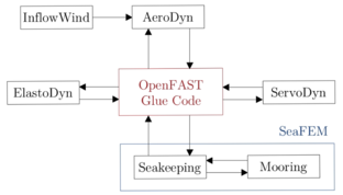
OpenFAST is a wind turbine multi-physics solver in the time-domain. It includes models to solve the aerodynamic effects using Blade Element Momentum Theory (BEMT), and the Free-Vortex Wake method (FVW). The hydrodynamic effects can be modeled with a potential flow solution, introducing viscous effects by means of the Morison’s equations [8]. Structural elasticity is characterized by linear modal representation using beam theory for the computation of tower, blades and platform deflections [23]. Its code structure is composed of different numerical modules for hydrodynamics (HydroDyn), mooring dynamics (MoorDyn), aerodynamics (AeroDyn), electrical system dynamics (ServoDyn), and structural dynamics (ElastoDyn), among others. These modules exchange information through a glue code (see Figure 1), where an input-output solve between modules is established. This facilitates the replacement of the hydrodynamic and mooring dynamic modules by SeaFEM.
Figure 1. OpenFAST modularization framework.
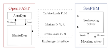
The aero-servo-elastic numerical models from OpenFAST are coupled with SeaFEM as shown in Figure 2, providing a solution for the rigid-body kinematics as well as the aerodynamic loads on the rotor blades, including the control of the servo-motor. While SeaFEM computes the seakeeping loads and the effect of the mooring lines. This tightly coupling is performed by imposing the rigid-body motions of the whole system obtained from OpenFAST, as boundary conditions for the seakeeping hydrodynamics problem in SeaFEM. Then, the loads computed within SeaFEM are sent to ElastoDyn’s module. Within this module, additionally, the loads coming from the turbine computed by AeroDyn are received. This total balance of loads is used to solve the motion equation in OpenFAST based on Kane’s method providing a solution of the kinematics, received by SeaFEM to update the platform position.
Figure 2. SeaFEM-OpenFAST data exchange.
The data exchange happens for every iteration and time step at the global reference point (0,0,0) located in the mean sea level. SeaFEM solves with respect to the total center of gravity, hence exchanged data is constantly translated from coordinate systems. The relationship between ElastoDyn’s kinematics and SeaFEM’s loads is linearized in each time step by computing a Jacobian matrix. SeaFEM is informed when this Jacobian needs to be updated. The tight coupling scheme is based on a fourth-order Runge-Kutta predictor-corrector solution algorithm with the number of correction steps defined by the user.
The linking of both codes is configured by compiling SeaFEM as an executable (.exe) and OpenFAST v.3.5.0 as a dynamic link library (.dll). The communication between executions is achieved through C++/Fortran interfaces with shared functions, having one in each code. This is necessary to ensure a data type compatibility in the imported procedures, since both codes do not share the same programming language. The exchange subroutines are exported from SeaFEM and imported into OpenFAST. This allows the code flow to jump from one code to another enabling the interaction between both, as shown in the flow chart from Figure 3.
Figure 3. Coupling strategy and time synchronization.
SeaFEM’s executable initializes OpenFAST, which dominates the simulation time line and accesses SeaFEM when needed. The information is exchanged by coupling subroutines following a logical order: Process 1, OpenFAST sends the turbine loads to SeaFEM in a separate process due to the interest of receiving them before solving the kinematics; Process 2, OpenFAST sends the kinematics variables, and SeaFEM computes and sends back the hydrodynamics and mooring loads; Process 3, synchronizes temporarily the two codes, SeaFEM is notified to update its time step when OpenFAST goes to the next one; Process 4, ends the computation when the maximum simulation time is reached. The calling of the same subroutines order is repeated in every iteration during the simulation.
The current calculation state in OpenFAST is communicated to SeaFEM through state tags following the simulation order (see Table 1). These tags are updated depending on the subroutine executed by OpenFAST that calls SeaFEM. Based on these, SeaFEM decides which process to follow, either to go to the next time step, or to compute wave and mooring loads. In this way, SeaFEM is used as an external loads calculator, being accessed only when needed from OpenFAST.
Table 1. State tags used for synchronization.
| State tag | Description |
| No_fast = 0 | No coupling with OpenFAST |
| Fast_initiate = 1 | OpenFAST dll is initialized |
| Fast_iterate = 2 | Iteration stage |
| Fast_update = 3 | Time step update |
| Fast_end = 4 | Computation end |
2.2. Multi-Turbine Extension
The extension for the multi-wind turbine solution is performed by coupling one execution of SeaFEM with as many OpenFAST instances as turbines placed on the platform. In this way, the aerodynamic components regarding each turbine are taken into account in the load balance. Besides, the turbines operate with their own servo control, being possible to simulate a platform containing several turbines with different features.
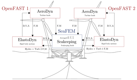
The OpenFAST instances solve each turbine independently, so that the dynamic interaction is performed through the floater. In Figure 4, a chart with the exchanged information between the OpenFAST modules and SeaFEM is displayed. It is shown how the turbine loads and rigid-body motions are provided to SeaFEM. Whereas SeaFEM returns the computed hydrodynamic loads including the additional turbine loads. With this approach, the aerodynamic wake interferences between adjacent turbines are neglected. However, for turbines placed side by side this interference is assumed to be a non-dominant effect.
Figure 4. Twin-turbine extension strategy for the simulation of the W2Power platform.
Although the present methodology can be used for an arbitrary number of turbines on the same platform, it is presented in this work for the W2Power twin turbine concept. As there are two OpenFAST executions coupled, one regarding each turbine, the equation of motion is solved twice, obtaining a kinematic solution for each one. Given that the entire structure is considered as a single rigid-body, both kinematic solutions should be equal. To avoid small numerical differences, in every iteration, the platform motions are averaged according to Eq. (1).
|
|
(1) |
Where are the averaged accelerations, velocities and displacements in the platform six DOFs and n the OpenFAST instance or turbine.
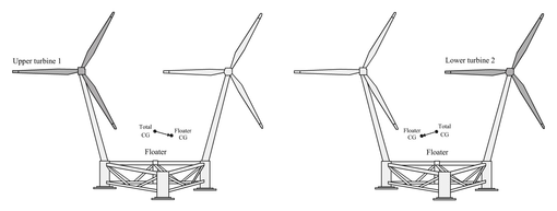
Figure 5. Mass - inertia components in each OpenFAST instance (left: OF1, right: OF2).
When OpenFAST solves a single floating wind turbine, it deals with the turbine, tower and platform mass properties . For the implementation of multi-turbine capabilities the additional tower and turbine mass components need to be included. These mass matrices are taken into account as part of the floater , which groups the platform , all the towers and the additional wind turbines and . The own turbine definition is maintained in OpenFAST, while the tower is neglected. Reason found in ElastoDyn’s simulation capabilities, which are restricted to straight towers, being multi-turbine concepts generally characterized by having leaning towers. However, it is worth noting that, if coupled with SubDyn, tilted towers could be modeled. The floater gravity center is computed regarding each OpenFAST execution, see Figure 5. The mass matrix of the floater is composed as in Eq. (2, 3) and considered within OpenFAST as the platform.
|
|
(2) | |
|
|
(3) |
Being the index used to indicate the components owing to the lower and upper rotors or OpenFAST instance.
The addition of turbines operating on the same platform implies a set of extra loads acting over the rigid-body response. These loads need to be taken into account within the total load balance. OpenFAST internally considers the aerodynamic loads of its own turbine . Whereas SeaFEM loads include the platform seakeeping and mooring loads. The loads from all the additional turbines are regarded as external loads to be added to the SeaFEM loads as in Eq. (4). These resulting loads are then returned to the OpenFAST executions , which added to the own turbine loads compose the total load balance , see Eq. (5). In this way, the additional loads acting on the other turbines are considered as external loads on the floater, reaching a dynamic influence between turbines.
|
|
(4) | |
|
|
(5) |
Where the index indicates the reference system and corresponding OpenFAST instance. SeaFEM terms are referred at the total center of gravity and the resulting loads are translated to each OpenFAST origin.
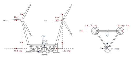
SeaFEM’s reference system is used as the global reference system. For the W2power platform, this origin of coordinates is located at the mean sea level and at the center of the upwind column. The X axis is oriented along the downwind direction and the Z direction facing upwards. Turbine loads acting on top of the tower are sent at the local hub reference systems. The kinematics are obtained at the OpenFAST global references, placed at the mean sea level and on a perpendicular line passing through the yaw axis of the corresponding turbine. SeaFEM computes the seakeeping hydrodynamics and mooring loads with respect to the total center of gravity. Exchanged data are related by constantly translating from the coordinate system of the sender, to the one of the receiver. The reference frames layout is presented in Figure 6.
Figure 6. Location of the reference frames for a twin turbine solution (left: front view, right: top section view).
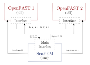
For the twin-turbine extension, two OpenFAST dlls are required to be linked with SeaFEM, as displayed in Figure 7. The initialization of both dlls is parallelized within the SeaFEM code by means of two OpenMP threads in charge of launching each OpenFAST execution. There is no direct communication between the dlls, being the information flow centralized in SeaFEM’s interface. The first OpenFAST execution controls the time-loop while SeaFEM plays the role of a calculator, called from OpenFAST when necessary. Within the SeaFEM interface, a synchronization is performed to keep both OpenFAST flows at the same point of execution, avoiding overlapping and time lags. The parallelization does not finish until the total simulation time is reached, having two mixed flows accessing SeaFEM simultaneously. To avoid interferences between them, the shared processes are duplicated.
Figure 7. Linking configuration and interface communication.
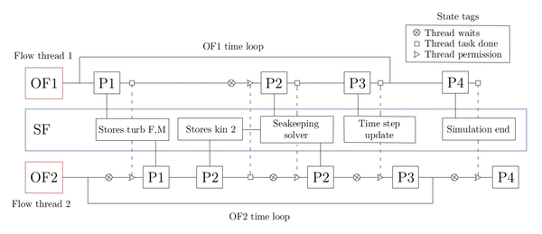
A synchronization strategy is performed to avoid overlays or time lags between threads ensuring common execution points. This is implemented at the SeaFEM interface, where it is possible to identify the thread that is accessing. State labels are associated to each thread depending on the simulation stage. The thread flow is stopped and waits until the other has finished a specific task, being informed by the state tag. As represented in the block diagram from Figure 8, the OpenFAST1 controls the total time line, giving permission to SeaFEM and OpenFAST2 to update its time step. Besides, after each communication process performed by OpenFAST2, its thread flow is stopped, waiting for permission given after the same process finished by OpenFAST1. The process 2 is split to gather all the kinematic solutions for its average before computing the SeaFEM loads. The tasks that need to be carried out once remain in charge of the dominant OpenFAST, while the other one just waits to avoid task repetition. In this way, the temporal synchronization for the three coupled instances is achieved without having interferences between them.
Figure 8. Extension strategy and thread synchronization.
3. Results: Intercode Comparison
The solver capabilities are tested for a single turbine and a twin-turbine concept. Given the lack of numerical benchmark data regarding multi-turbine configurations, a methodology is proposed for the verification of the implemented framework. The seakeeping performance is contrasted between the computed by only SeaFEM with the obtained from the present tool, computed by OpenFAST rigid-body solution. Simulations with only wave excitations and combined load cases including wind are analyzed.
3.1. OC3 Hywind
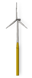
The floating spar-buoy concept “Hywind”, belonging to the OC3 project is used as a benchmark model to compare the numerical results against other strategies. As part of the phase IV, the coupled dynamic response of the NREL 5-MW reference wind turbine installed on the Hywind platform with catenary mooring lines is analyzed. The technical description of the NREL-5MW turbine and the Hywind platform, are found in [24, 25], respectively. In Table 2, the OC3-Hywind platform specifications are summarized.
Table 2. OC3-Hywind platform particulars.
| Unit | Value | ||
| Mass (with ballast) | kg | 7,466,330 | |
| Downwind distance of CM | m | 0.00 | |
| Lateral distance of CM | m | 0.00 | |
| Vertical distance of CM | m | -89.9155 | |
| Roll inertia about CM | kg·m2 | 4,229,230,000 | |
| Pitch inertia about CM | kg·m2 | 4,229,230,000 | |
| Yaw inertia about CM | kg·m2 | 164,230,000 |
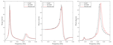
Response Amplitude Operators (RAOs) are compared to FAST using its own hydrodynamic model, and coupled with results computed by WAMIT. The RAOs computed solution for the rigid floating system subjected to a simplified case with no wind or currents are obtained. In the present tool, the prediction of the wave-body interaction is performed with a time-domain simulation using a white noise wave spectrum. Extracted RAOs referred at the origin are compared to previously published by NREL [26]. The RAOs comparison for the relevant degrees of freedom is shown in Figure 9. Only small differences are observed in surge peak amplitude and pitch frequency at their natural frequencies. This can be due to small differences in the numerical parameters of the different analyses, which have not been reported in the consulted references.
Figure 9. OC3-Hywind: RAOs comparison (no-wind, rigid turbine).
The transfer of turbine loads is verified in contrast with SeaFEM own rigid-body solution. A case with a steady wind condition in the absence of waves is computed. The wind force along the upwind direction over the rotors is extracted from the present framework simulation. Same case configuration is computed in SeaFEM, in which previous extracted load is introduced as a precomputed external load. Surge motions are compared between both simulations since being the most excited. Results are presented in Figure 10 for the OC3-Hywind showing that both solutions coincide, and hence proving that the data exchange works properly.
3.2. W2Power
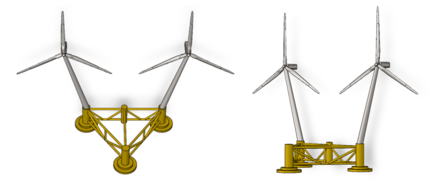
As part of the H2020 European Project FIBREGY [27], the full-scale W2Power platform concept design in Fiber-Reinforced Polymers (FRP) is tested. This semisubmersible platform holds two towers inclined outwards, being the wind turbines placed side by side. The mooring system is arranged in a single point at the front column and allows the platform to align itself towards the wind. The W2Power concept specifications, as well as results plot axis, cannot be shown due to confidentiality reasons. More information can be found in [28]. The FRP-W2Power platform with the NREL 5-MW reference wind turbines installed on each tower, is used for the intercode verification of the multi-turbine extension. A comparison of its dynamic response is analyzed considering a deep-water depth of 200 m. Figure 11 provides a scheme of the system platform-turbines.
Figure 11. Multi-Turbine system (left: front-top view, right: front-side view).
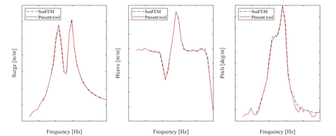
RAOs are computed with the multi-turbine extended tool and compared with SeaFEM using its own rigid-body dynamics solver. A time-domain simulation using a white noise head wave spectrum is performed in the absence of wind. Figure 12 displays a comparison of RAOs for the relevant degrees of freedom referred at the center of mass. A good agreement is observed between both rigid-body solutions.
The verification of exchanged turbine loads is also performed following same methodology and load case condition as for the OC3-Hywind, a constant wind velocity without waves. The wind force in surge over the rotors is extracted from the present coupled simulation framework. Same case is computed afterwards in SeaFEM introducing the sum of the extracted loads in both turbines as an external load. Displacement, velocity and acceleration in surge are presented in Figure 13. Both solutions agree, showing that the coupling strategy is properly implemented.
Figure 13. W2Power: Surge motions (no-waves, rigid turbines).
4. Discussions
The present solver is designed to compute the coupled dynamic analysis of the two-way fluid-structure interaction, of the wind loads acting over the rotor and wave loads on the platform. Current multi-turbine approach is implemented for the analysis of twin turbine concepts, being easily extended to an arbitrary number of turbines by applying the same methodology. Since having several OpenFAST executions, it is possible to analyze a platform handling turbines with their own features and control systems in different operation conditions. For the present application, the aerodynamic wake interferences are not considered since it is assumed not to be a dominant effect in turbines placed side by side. This implies a limitation when analyzing nearby or not co-planar rotors. As future research line, these effects can be implemented, being particularly interesting for the analysis of the in-field blockage effect in multi-rotor concepts or configurations with downstream turbines.
The seakeeping hydrodynamic solution and its handling of non-linear effects is upgraded with the coupling of SeaFEM in the OpenFAST framework. Since using the Finite Element Method, versatility is provided in the structural designs that can be analysed. This implies an improvement regarding other methods, designed for standarized concepts, reestricted to cilindrical sections and beam models. Hence, the present tool can cover the range of innovation and future proposals in the increasing variety of multi-rotor systems.
In addition, it is able to compute structural concepts with leaning towers, which is a common feature of multi-rotor platforms. As well, multi-rotor configurations are characterized by having large platforms where elastic deformations might be significant. In this work these effects cannot be assessed for the platform and towers, since SeaFEM is coupled to Elastodyn, where the structural solution of the platform is restricted to rigid body motions. As a future work, it is considered to perform the coupling through SubDyn, so that the platform elasticity could be modeled allowing to perform hydro-elastic analysis. Furthermore, the present method can be easily combined with SeaFEM hydro-elastic capabilities. This solution is able to execute detailed structural analysis, being suitable to simulate the elastic behavior and accumulated fatigue damage of an offshore wind platform. Although being the structural assessment a main concern in floating offshore platforms, rigid-body dynamic analyses are mainly performed in multi-rotor concepts. Therefore, the present work aims to set the numerical framework for a complete simulation tool, including elastic effects and covering the whole multi-physic problem.
5. Conclusions
This work presents a methodology for the development of a numerical solver addressed to single and multi-turbine offshore platforms. This tool allows to perform the coupled analysis of these platforms, covering its combined structural response and power production. The present time-domain numerical framework is able to compute the aero-hydro-servo-elastic solution of these structures subjected to environmental loads. It is based on the turbine dynamics simulator OpenFAST, tightly coupled with the seakeeping hydrodynamics solver SeaFEM.
An assessment method is proposed following an intercode comparison process of the seakeeping rigid-body response in single and multi-turbine platforms. Natural frequencies and peak amplitudes of the response amplitude operators are well predicted. Results consistency is found in surge motions under wind conditions. The developed multi-rotor tool is tested on the FRP design of the full-scale W2Power platform, showing a good agreement between the contrasted numerical strategies.
Author Contributions: Conceptualization, J.G.-E. and B.S.-C; methodology, B.S.-C and I.B.-P; implementation and verification, I.B.-P; writing, I.B.-P; review and editing, J.G.-E. and B.S.-C. All authors have read and agreed to the published version of the manuscript.
Funding: This research was funded by the European Commission under the grant agreements H2020 FibreGy (ref. 952966) and H2020 Fibre4Yards (ref. 101006860), and by the Spanish “Ministerio de Ciencia e Innovacion” under the grant agreement MLAMAR (ref. PID2021-126561OB-C31).
Acknowledgments: The authors are thankful to all the partners on the above mentioned research projects, and in particular to Enerocean and its contribution by sharing relevant data for the analysis of its platform concept W2Power.
References
- 1. Jamieson, P.; Branney, M. Multi-Rotors; A Solution to 20 MW and Beyond? J. Energy Procedia. 2012. Doi: 10.1016/j.egypro.2012.06.086 [View PDF] [Google Scholar]
- 2. Xiong, X.; Laima, S.; Li, H. Experimental study of the wake of multi-rotor turbine. J. Ocean Eng. 2023. Doi: 10.1016/j.oceaneng.2022.113594 [Google Scholar]
- 3. Martin, R.; Benito, P.; Azcona, J.; Cuerva, A. Influence of lateral rotor spacing on the benefits in power generated by multi-rotor configurations. J. Phys. Conf. Ser. 2022. Doi: 10.1088/1742-6596/2362/1/012024 [View PDF] [Google Scholar]
- 4. Martin, R. Coupled Dynamics of Multi Wind Turbine Floating Platforms. PhD Thesis, Escuela Técnica Superior de Ingeniería Aeronáutica y del Espacio. 2022. [View PDF] [Google Scholar]
- 5. Bae, Y.; Kim, M. The Dynamic Coupling Effects of a MUFOWT (Multiple Unit Floating Offshore Wind Turbine) with Partially Broken Blade. J. Ocean Wind Energy. 2015. [View PDF] [Google Scholar]
- 6. Barltrop, N. Multiple Unit Floating Offshore Wind Farm (MUFOW). J. Wind Eng. 1993; pp. 183–188. [Google Scholar]
- 7. Bae, Y. Coupled dynamic analysis of multiple unit floating offshore wind turbine. PhD Thesis, Texas A&M University. 2013. [View PDF] [Google Scholar]
- 8. Jonkman, J. M.; Sclavounos, P. Development of Fully Coupled Aeroelastic and Hydrodynamic Models for Offshore Wind Turbines. ASME Wind Energy Symposium Reno, Nevada. 2006. Doi: 10.2514/6.2006-995 [View PDF] [Google Scholar]
- 9. Campaña, G.; Martín, R.; Méndez, B.; Benito, P.; Azcona, J. OF2: coupling OpenFAST and OpenFOAM for high fidelity aero-hydro-servo-elastic FOWT simulations. European academy of Wind Energy. 2023. Doi: 10.5194/wes-8-1597-2023 [View PDF] [Google Scholar]
- 10. Brown, K.; Cheung, L.; Hsieh, A.; Maniaci, D.; Hamilton, W. Wake interactions behind individual-tower multirotor wind turbine configurations. J. Phys.: Conf. Ser. 2023. Doi: 10.1088/1742-6596/2505/1/012041 [View PDF] [Google Scholar]
- 11. El Beshbichi, O.; Xing, Y.; Chen Ong, M. Modelica-AeroDyn: Development, benchmark, and application of a comprehensive object-oriented tool for dynamic analysis of non-conventional horizontal-axis floating wind turbines. J. Wind Energy. 2023. Doi: 10.1002/we.2814 [View PDF] [Google Scholar]
- 12. El Beshbichi, O.; Xing, Y.; Chen Ong, M. Dynamic analysis of two-rotor wind turbine on a spar-type floating platform. J. Ocean Eng. 2021. Doi: 10.1016/j.oceaneng.2021.109441 [View PDF] [Google Scholar]
- 13. Bashetty, S.; Ozcelik, S. Design and Stability Analysis of an Offshore Floating Multi-Wind Turbine Platform. J. Invent. 2022. Doi: 10.3390/inventions7030058 [View article] [Google Scholar]
- 14. Martin, R.; Benito, P.; Azcona, J.; Cuerva, A. Validation of a free vortex filament module for the integrated simulation of multi-rotor wind turbines. J. Renew. Energy. 2021. Doi: 10.1016/j.renene.2021.07.147 [Google Scholar]
- 15. Van der Laan, M.P.; Andersen, S.J.; Ramos García, N.; Angelou, N.; Pirrung, G.R.; Ott, S.; Sjöholm, M.; Sørensen, K.H.; Vianna Neto, J.X.; Kelly, M.; et al. Power curve and wake analyses of the Vestas multi-rotor demonstrator. J. Wind Energy Sci. 2019. Doi: 10.5194/wes-4-251-2019 [View article] [Google Scholar]
- 16. N, S, Ghaisas.; A, S, Ghate.; S, K, Lele. Large-eddy simulation study of multi-rotor wind turbines. J. Phys. Conf. Ser. 2018. Doi: 10.1088/1742-6596/1037/7/072021 [View PDF] [Google Scholar]
- 17. Lamei, A.; Hayatdavoodi, M.; Riggs, H.R. Motion and elastic response of wind-tracing floating offshore wind turbines. J. Ocean Eng. Mar. Energy. 2023. Doi: 10.1007/s40722-022-00250-1 [View PDF] [Google Scholar]
- 18. Servan-Camas, B.; Garcia-Espinosa, J. Accelerated 3D multi-body seakeeping simulations using unstructured finite elements. J. Comput. Phys. 2013; pp. 382–403. Doi: 10.1016/j.jcp.2013.06.023 [View article] [Google Scholar]
- 19. Servan-Camas, B.; Gutierrez, JE.; Garcia-Espinosa, J. A time-domain second-order FEM model for the wave diffraction-radiation problem. Validation with a semisubmersible platform. Mar. Struct. 2018; pp. 278–300. Doi: 10.1016/j.marstruc.2017.12.001 [View PDF] [Google Scholar]
- 20. International Centre for Numerical Methods in Engineering. Available online: www.cimne.com (accessed on 26 October 2023).
- 21. Compass IS. SeaFEM documentation. Available online: https://www.compassis.com/tdyn/comportamiento-en-la-mar-seafem/ (accessed on 20 December 2023).
- 22. Garcia-Espinosa, J.; Servan-Camas, B.; Calpe, M. High fidelity hydroelastic analysis using modal matrix reduction. J. Mar. Sci. Eng. 2023. Doi: 10.3390/jmse11061168 [View article] [Google Scholar]
- 23. Jonkman, J. M. Dynamics Modeling and Loads Analysis of an Offshore Floating Wind Turbine. Technical Report NREL/TP-500-41958. 2007. Doi: 10.2172/921803 [View PDF] [Google Scholar]
- 24. Jonkman, JM.; Butterfield. S.; Musial, W.; Scott, G. Definition of a 5-MW Reference Wind Turbine for Offshore System Development. Technical Report NREL/TP-500-38060. 2009. Doi: 10.2172/947422 [View PDF] [Google Scholar]
- 25. Jonkman, JM. Definition of the Floating System for Phase IV of OC3. Technical Report NREL/TP-500-47535. 2010. Doi: 10.2172/979456 [View PDF] [Google Scholar]
- 26. Ramachandran, GKV.; Robertson, A.; Jonkman, JM.; Masciola, MD. Investigation of Response Amplitude Operators for Floating Offshore Wind Turbines. 23rd International Ocean, Offshore and Polar Engineering Conference. 2013. [View PDF] [Google Scholar]
- 27. International Centre for Numerical Methods in Engineering. Development, engineering, production and life cycle management of improved FIBRE-based material solutions for the structure and functional components of large offshore wind enerGY and tidal power platforms. Proposal Materials for offshore energy, 2020.
- 28. Enerocean. Available online: https://enerocean.com/w2power/ (accessed on 26 October 2023).
- 29. DNV. Using Sesam and Bladed in one workflow. Available online: https://www.dnv.com/Publications/sesam-and-bladed-149064 (accessed on 20 December 2023).
- 30. QBlade Theory Guide. Available online: https://docs.qblade.org/src/theory/index_th.html (accessed on 20 December 2023).
- 31. Orcina. Orcaflex documentation. Available online: https://www.orcina.com/resources/documentation/ (accessed on 20 December 2023).
Document information
Published on 01/01/2024
DOI: 10.3390/jmse12010085
Licence: CC BY-NC-SA license
