| (3 intermediate revisions by the same user not shown) | |||
| Line 128: | Line 128: | ||
In order to study the influence of bolt preload distribution on the mode of compressor sealing system, the working condition is defined by the distribution state of bolt preload on the joint surface, as shown in [[#tab-2|Table 2]]. <math display="inline">F_0</math> is the rated preload of single bolt. The marks 1~20 represent the pre-tightening force of each bolt. The definition of the operating condition reflects the process of the bolt group from degradation to loosening during operation. Case-1 is the normal working condition and the rated pre-tightening force. Case-2 and Case-3 mainly reflect the overall deterioration of the pre-tightening force of the bolt group. Case-4 and Case-5 mainly reflect the partial loosening and damage of the bolt group. | In order to study the influence of bolt preload distribution on the mode of compressor sealing system, the working condition is defined by the distribution state of bolt preload on the joint surface, as shown in [[#tab-2|Table 2]]. <math display="inline">F_0</math> is the rated preload of single bolt. The marks 1~20 represent the pre-tightening force of each bolt. The definition of the operating condition reflects the process of the bolt group from degradation to loosening during operation. Case-1 is the normal working condition and the rated pre-tightening force. Case-2 and Case-3 mainly reflect the overall deterioration of the pre-tightening force of the bolt group. Case-4 and Case-5 mainly reflect the partial loosening and damage of the bolt group. | ||
| − | + | <div class="center" style="font-size: 75%;">'''Table 2'''. Working conditions</div> | |
<div id='tab-1'></div> | <div id='tab-1'></div> | ||
{| class="wikitable" style="margin: 1em auto 0.1em auto;border-collapse: collapse;font-size:85%;width:auto;" | {| class="wikitable" style="margin: 1em auto 0.1em auto;border-collapse: collapse;font-size:85%;width:auto;" | ||
|-style="text-align:center" | |-style="text-align:center" | ||
| − | ! Case !! Pretensioning force distribution | + | ! style="text-align: left;| Case !! Pretensioning force distribution |
|- | |- | ||
| style="text-align: center;vertical-align: top;"|Case-1 | | style="text-align: center;vertical-align: top;"|Case-1 | ||
| Line 157: | Line 157: | ||
{| class="wikitable" style="margin: 0em auto 0.1em auto;border-collapse: collapse;width:auto;" | {| class="wikitable" style="margin: 0em auto 0.1em auto;border-collapse: collapse;width:auto;" | ||
|-style="background:white;" | |-style="background:white;" | ||
| − | |style="text-align: center;padding:10px;"| [[Image:Review_326545415492-image5.png| | + | |style="text-align: center;padding:10px;"| [[Image:Review_326545415492-image5.png|500px]] |
|- | |- | ||
| style="background:#efefef;text-align:left;padding:10px;font-size: 85%;"| '''Figure 5'''. Modal analysis results of diaphragm compressors under different operating conditions | | style="background:#efefef;text-align:left;padding:10px;font-size: 85%;"| '''Figure 5'''. Modal analysis results of diaphragm compressors under different operating conditions | ||
| Line 170: | Line 170: | ||
{| class="wikitable" style="margin: 0em auto 0.1em auto;border-collapse: collapse;width:auto;" | {| class="wikitable" style="margin: 0em auto 0.1em auto;border-collapse: collapse;width:auto;" | ||
|-style="background:white;" | |-style="background:white;" | ||
| − | |style="text-align: center;padding:10px;"| [[Image:Review_326545415492-image6.png| | + | |style="text-align: center;padding:10px;"| [[Image:Review_326545415492-image6.png|500px]] |
|- | |- | ||
| style="background:#efefef;text-align:left;padding:10px;font-size: 85%;"| '''Figure 6'''. Frequency domain analysis of the air cavity pressure | | style="background:#efefef;text-align:left;padding:10px;font-size: 85%;"| '''Figure 6'''. Frequency domain analysis of the air cavity pressure | ||
| Line 284: | Line 284: | ||
|style="text-align: center;padding:10px;"| [[Image:Review_326545415492-image8.png|600px]] | |style="text-align: center;padding:10px;"| [[Image:Review_326545415492-image8.png|600px]] | ||
| − | [[Image:Review_326545415492-image9.png| | + | [[Image:Review_326545415492-image9.png|600px]] |
|- | |- | ||
| style="background:#efefef;text-align:left;padding:10px;font-size: 85%;"| '''Figure 8'''. Stress distribution diagram of sealing system under different working condition | | style="background:#efefef;text-align:left;padding:10px;font-size: 85%;"| '''Figure 8'''. Stress distribution diagram of sealing system under different working condition | ||
| Line 290: | Line 290: | ||
| − | From [[#img-8|Figure 8]], it can be obtained that the sealing ring compression rate, sealing ring diameter, sealing groove width and depth have a sensitive nonlinear relationship on the contact stress, especially the sealing ring compression rate has a significant impact on the sealing performance of diaphragm compressor. With the same sealing ring and groove structure, the contact pressure between the sealing ring and groove increases significantly with the increasing compression rate. With the increase of compression ratio by 20% and 25%, the contact pressure increased by 42.0% and 77.5%, respectively. From Figure 9, it can be concluded that for the sealing ring with diameter of 5.3mm, the contact pressure changes slightly when the seal groove width is appropriately increased without changing the seal groove depth. However, for the sealing ring with diameter of 7.0 mm, the contact pressure decreases significantly when the sealing groove width is increased, especially at high compression rate. At c=25%, d=7. | + | From [[#img-8|Figure 8]], it can be obtained that the sealing ring compression rate, sealing ring diameter, sealing groove width and depth have a sensitive nonlinear relationship on the contact stress, especially the sealing ring compression rate has a significant impact on the sealing performance of diaphragm compressor. With the same sealing ring and groove structure, the contact pressure between the sealing ring and groove increases significantly with the increasing compression rate. With the increase of compression ratio by 20% and 25%, the contact pressure increased by 42.0% and 77.5%, respectively. From [[#img-9|Figure 9]], it can be concluded that for the sealing ring with diameter of 5.3mm, the contact pressure changes slightly when the seal groove width is appropriately increased without changing the seal groove depth. However, for the sealing ring with diameter of 7.0 mm, the contact pressure decreases significantly when the sealing groove width is increased, especially at high compression rate. At <math>c=25</math>%, <math>d=7.0</math>mm, the maximum contact pressure is reduced by 8.1% by increasing the groove width by 0.5 mm. Therefore, at the same compression rate of the sealing ring, the contact pressure at the sealing interface increases with the increase of the diameter of the seal ring, and the structural size of the sealing groove has a significant nonlinear impact on the contact pressure of the large-diameter sealing ring. |
<div id='img-9'></div> | <div id='img-9'></div> | ||
Latest revision as of 10:24, 19 December 2023
Abstract
Under the combined action of structure-process -load, the stiffness and stress distribution at the sealing interface of the ultra-high pressure diaphragm compressor cylinder head exhibit significant nonlinear and uncertain characteristics, resulting in damage to the sealing interface, diaphragm and sealing ring. This paper first establishes a finite element numerical model considering assembly process parameters based on sudden impact load conditions, and analyzes the dynamic characteristics under different assembly process parameters. It is found that some modal frequencies transition with bolt loosening. Then, the mechanical characteristics of the assembly interface of the compressor sealing system under sudden impact load were studied. The maximum equivalent stress at the assembly interface was 298.9 MPa, and the maximum deformation at the top of the air chamber was 0.167mm. Finally, the nonlinear effects of sealing ring compression rate, sealing ring diameter, and sealing groove structure on contact stress and sealing performance were obtained. The results show that as the compression ratio increases by 20% and 25%, the contact pressure at the sealing interface increases by 42.0% and 77.5%, respectively; When the compression rate is 25%, the width of the sealing groove increases by 0.5mm, and the maximum contact pressure decreases by 8.1%. The research on the dynamic characteristics and sealing performance of diaphragm compressors provides technical support for the structural optimization design of diaphragm compressors cylinder head.
Keywords: Diaphragm compressor, sudden impact load, bolted structure, sealing performance
1. Introduction
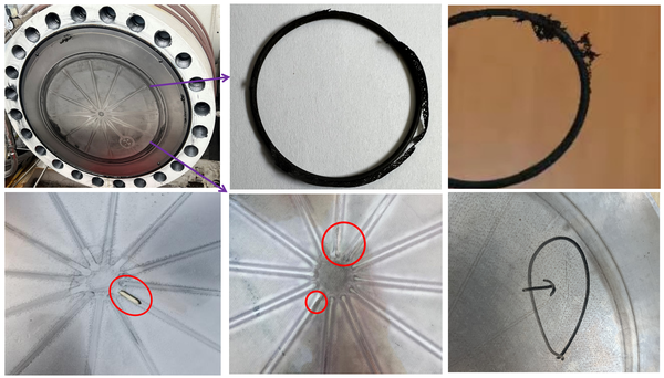
The high-pressure diaphragm compressor is a core component in the hydrogen refueling station system, and its performance has a significant impact on the performance and cost of the hydrogen refueling station [1]. The sealing performance and manufacturing economy of the sealing device of a diaphragm compressor directly determine the operating cost, performance, and safety of the diaphragm compressor. With the increasing demand for high hydrogen storage density in hydrogen refueling stations, higher technical requirements have been put forward for the working pressure and temperature of hydrogen refueling station compressors, posing higher challenges to the sealing and stability of compressors in service [2-4]. Key components of diaphragm compressors, such as sealing rings and diaphragms, often undergo premature damage (Figure 1), leading to seal failure. Therefore, ensuring the reliability of key components of the sealing system of the ultra-high pressure(≥100MPa) diaphragm compressor in the hydrogen refueling station has become a key problem that needs to be urgently solved.
|
| Figure 1. Failure modes of key components for diaphragm compressors |
Researchers have carried out a lot of work on the sealing performance, dynamic characteristics, and structural optimization design of the diaphragm compressor. Wang et al. [5,6] and Jia et al. [7] studied the mechanical characteristics analysis, structural optimization, and fatigue life prediction of key components such as exhaust holes in diaphragm compressor cylinder heads under high-temperature and high-pressure conditions through a combination of experiments and numerical simulations. Ren et al. prosed a mathematical model of volumetric efficiency for the diaphragm compressor considering the effects of clearance volume, suction gas overheating and pressure loss, and focused on the influence mechanism of hydraulic oil compressibility [8]. Some scholars focus on studying the cavity type of diaphragm compressors to increase the volume of the cavity, reduce the radial stress of the diaphragm, and improve the service life and reliability of the diaphragm [9-10]. Some scholars mainly study the motion law, contact stress, and fatigue damage of membranes to improve their service life [11-13]. What’s more, some scholars aim to improve the working efficiency of diaphragm compressors by improving the distribution of airways, the structural form and molding manufacturing techniques of diaphragms [14-15].
In order to improve the operational safety of diaphragm compressors, scholars have conducted research on non-destructive testing and fault diagnosis of diaphragm compressors. Bayrak proposed a distributed hydrogen generator fault detection method based on wavelet transform [16], and the non-destructive fault diagnosis method for diaphragm compressors in hydrogen refueling stations based on acoustic emission technology has achieved good engineering results [17]. Ren et al. proposed a detection method for diaphragm motion status based on dynamic changes in hydraulic oil pressure [18]. On this basis, Scholars have proposed using feature event signals to identify typical abnormal situations such as high oil pressure, slight insufficient oil pressure, and severe insufficient oil pressure, in order to reduce unplanned compressor shutdowns [19-20].
In summary, scholars have achieved a series of achievements in the mechanical characteristics, fatigue damage of the diaphragm, system fault diagnosis, and compression efficiency of the diaphragm compressor under thermal coupling conditions. At present, scholars mainly focus on the mechanical properties and fatigue reliability of a single key component under adverse conditions, while the sealing performance of diaphragm compressor needs to comprehensively consider the external excitation, sealing structure and assembly process. Single objective optimization and improvement cannot meet the sealing reliability and long life requirements of ultra-high pressure diaphragm compression.
Therefore, the purpose of this paper is to propose an optimization design method for the sealing structure of high pressure diaphragm compressors that comprehensively considers nonlinear coupling factors such as service conditions, sealing structure, and assembly process of diaphragm compressors. Firstly, a finite element numerical model considering assembly process parameters is established based on actual service conditions to analyze the dynamic characteristics under different assembly process parameters. Then, the mechanical characteristics of the assembly interface of the compressor sealing system under sudden impact loads are studied to provide boundary conditions for the design of the sealing structure. Finally, based on the characteristics of the sealing structure and the nonlinear constitutive relationship of the rubber ring, a numerical simulation contact model is established to reveal the relationship between the sealing ring compression rate, sealing ring diameter, sealing groove width and depth on contact stress and sealing performance.
2. Model and method
2.1 Structure and working conditions
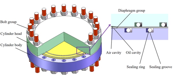
The diaphragm compressor of the hydrogenation station is mainly composed of cylinder head, cylinder block, metal diaphragm and sealing system, as shown in Figure 2. The air cavity consists of a cylinder head with a dome inner surface and a metal diaphragm. The oil cavity consists of a cylinder block with a dome inner surface and a metal diaphragm. The cylinder head, the cylinder block and the diaphragm are fastened together by the bolt assembly.
|
| Figure 2. Diaphragm compressor structure of hydrogen station |
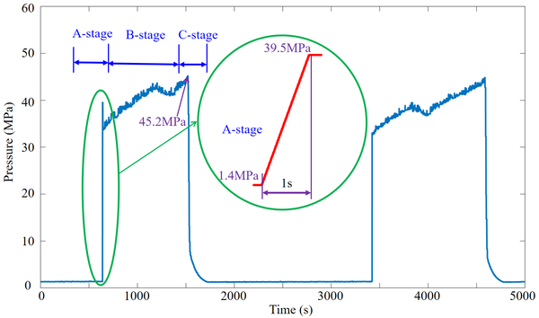
The cylinder head is equipped with an exhaust valve in the center and an inlet valve on both sides. The pressure change in the air cavity of the diaphragm compressor during hydrogen inlet/outlet process is shown in Figure 3. In A-stage, the air pressure in the cavity rises rapidly from 1.4MPa to 39.5MPa within 1 second; in B-stage, the air pressure rises slowly from 34.2MPa to 42.3MPa; in C-stage, the maximum value reaches 45.2MPa from 42.3MPa, and then suddenly drops to 9.9MPa. It can be seen from the pressure variation diagram of the air cavity that the pressure of the air cavity is a typical sudden impact load, especially the air pressure change in Phase A is the most violent, and the whole inlet/outlet working process presents the pulsation cycle characteristics.
|
| Figure 3. Pressure variation history of compressor air cavity |
2.2 Simulation model setup
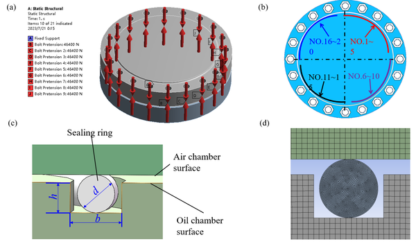
In order to study the mechanical properties of diaphragm compressor in service, numerical simulation models of modal analysis and transient dynamic analysis for diaphragm compressor are established based on finite element software (ANSYS 19.0), as shown in Figure 4(a). The material performance parameters of diaphragm compressor membrane head components are shown in Table 1. Three-dimensional solid element Solid95 is adopted for cylinder head, cylinder body, diaphragm and bolt group in numerical simulation model; Friction contact is adopted between cylinder head, cylinder body and diaphragm; Beam Connection is used to simulate the application of bolt preload. For convenience, the bolt group (No. 1-20) is divided into four zones (No. 1-5, No. 6-10, No. 11-15 and No. 16-20) in Figure 4(b). The rated pre-tightening force of bolts is 130N·m (Tightening normal force: 46.4kN).
The mating dimensions of the seal ring and the groove (Figure 4(c)) are determined by analyzing the strain, internal stress and contact stress of the seal ring at different compression rates, so as to achieve better sealing performance. The structure and load distribution of diaphragm compressor are completely symmetrical. To improve the calculation efficiency and simplify the model reasonably, 2D finite element contact simulation model is adopted, as shown in Figure 4(d).
|
| Figure 4. Pressure variation history of compressor air cavity |
| Part | (GPa) | (MPa) | (Kg/m3) | |
|---|---|---|---|---|
| Cylinder head | 206 | 0.3 | 740 | 7900 |
| Cylinder body | 209 | 0.27 | 600 | 7900 |
| Diaphragm | 193 | 0.31 | 207 | 7900 |
| Bolt group | 211 | 0.3 | 950 | 7900 |
| Sealing ring | 14 | 0.49 | 3.9 | 1000 |
3. Results and discussions
3.1 Prestress modal
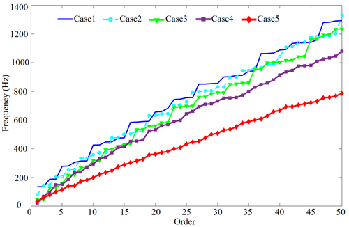
In order to study the influence of bolt preload distribution on the mode of compressor sealing system, the working condition is defined by the distribution state of bolt preload on the joint surface, as shown in Table 2. is the rated preload of single bolt. The marks 1~20 represent the pre-tightening force of each bolt. The definition of the operating condition reflects the process of the bolt group from degradation to loosening during operation. Case-1 is the normal working condition and the rated pre-tightening force. Case-2 and Case-3 mainly reflect the overall deterioration of the pre-tightening force of the bolt group. Case-4 and Case-5 mainly reflect the partial loosening and damage of the bolt group.
| Case | Pretensioning force distribution |
|---|---|
| Case-1 | (1~20) |
| Case-2 | 0.8 (1~20) |
| Case-3 | 0.5 (1~20) |
| Case-4 | 0(1~5), 0.5 (6~20) |
| Case-5 | 0(1~10), 0.5 (11~20) |
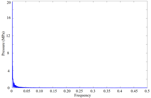
Based on different working conditions, the influence of joint preload distribution on natural frequency of diaphragm compressor sealing system is analyzed. The modal analysis results of diaphragm compressor sealing system are shown in Figure 5. Fourier transform is carried out for sudden impact load. Modal analysis results of diaphragm compressors under different operating conditions is shown in Figure 6.
|
| Figure 5. Modal analysis results of diaphragm compressors under different operating conditions |
As shown in Figure 5, the prestress mode of diaphragm compressor declines with the decrease of preload on Case-1~3, and the form keeps consistent. Partial modal frequency of Case-2 and Case-3, for example, the 36th and 45th order modes jump over the mode frequency of Case-1. These higher-order mode jumps reflect the phenomenon of bolt preload degradation. A sharp decrease in the modal frequency can be obtained from the loosening or fatigue fracture of some of the bolts simulated in Cases 4 and 5. The modal frequency of Cases 4 and 5 are approximately 16.5% and 39.2% lower than rated Case 1, respectively. The bolt loosening in partial areas has a significant impact on the modal frequency of diaphragm compressor, which can be used as a failure diagnosis method of bolt loosening for the diaphragm compressor bolted sealing system.
As shown in Figure 6, the frequency domain analysis of the abrupt impact load history in the actual working process of the diaphragm compressor shows that the load excitation is basically concentrated on the ultra-low frequency order, which is far lower than the first natural frequency of the rated working condition, and the risk of system resonance will not occur. So the damage of the compressor diaphragm is mainly fatigue damage under high additional stress.
|
| Figure 6. Frequency domain analysis of the air cavity pressure |
3.2 Transient dynamic analysis
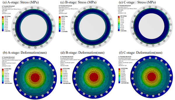
Based on working conditions of diaphragm compressor, the pressure of diaphragm compressor cavity is divided into three stages: rapid rise stage (A-stage), stable rise stage (B-stage) and rapid drop stage (C-stage) in Figure 3. The sealing interface contact stress and the deformation of the cylinder head at each stage are shown in Figure 7.
From Figure 7, it can be obtained that the maximum stress of bolted sealing interface in stages-A, B and C is 291.6 MPa, 298.9 MPa and 207.3 MPa respectively, and the maximum deformation of diaphragm compressor cylinder head is 0.147 mm, 0.157 mm and 0.167 mm, respectively. The interface pressure of A-stage and B-stage is basically the same, while the interface pressure of C-stage assembly is 30.6% lower than that of B-stage. The pressure at the diaphragm compressor assembly interface mainly depends on the combined action of bolt preload and cavity working pressure. With the increase of the cavity pressure of the diaphragm compressor, the comprehensive pressure of the interface is reduced, resulting in the most obvious reduction of the maximum pressure of the interface in the C-stage, which provides the design basis for the analysis of the interface seal of the diaphragm compressor.
|
| Figure 7. Stress and deformation of key components of diaphragm compressors |
The maximum deformation of the diaphragm compressor cavity gradually increases in A-stages, B-stages to C-stages. The deformation of the cavity mainly depends on the pressure of the cavity. With the change of the maximum pressure of the cavity, the maximum deformation of the cavity increases accordingly. C-stage cavity pressure peaks and deformation reaches a maximum of 12.0% more than A-stage. The determination of the maximum deformation of the cavity provides boundary conditions for the design of the cavity curve.
3.3 Sealing performance analysis
Based on the rated pressure () of diaphragm compressor and the diameter of sealing ring (), the matching dimension (width , depth ) of sealing groove is determined by analyzing the deformation, equivalent stress and contact stress of sealing interface under different compression rates. In order to study the relationship between compression ratio () of the sealing ring, diameter of the sealing ring, structure dimensions the sealing groove and sealing performance, the combination types of the parameters are in Table 3.
| Case | (%) | (mm) | (mm) | (mm) |
|---|---|---|---|---|
| 1 | 15 | 5.3 | 5.8 | 3.9 |
| 2 | 15 | 5.3 | 6.3 | 3.9 |
| 3 | 15 | 7 | 7.5 | 5.2 |
| 4 | 15 | 7 | 8 | 5.2 |
| 5 | 20 | 5.3 | 5.8 | 3.9 |
| 6 | 20 | 5.3 | 6.3 | 3.9 |
| 7 | 20 | 7 | 7.5 | 5.2 |
| 8 | 20 | 7 | 8 | 5.2 |
| 9 | 25 | 5.3 | 5.8 | 3.9 |
| 10 | 25 | 5.3 | 6.3 | 3.9 |
| 11 | 25 | 7 | 7.5 | 5.2 |
| 12 | 25 | 7 | 8 | 5.2 |
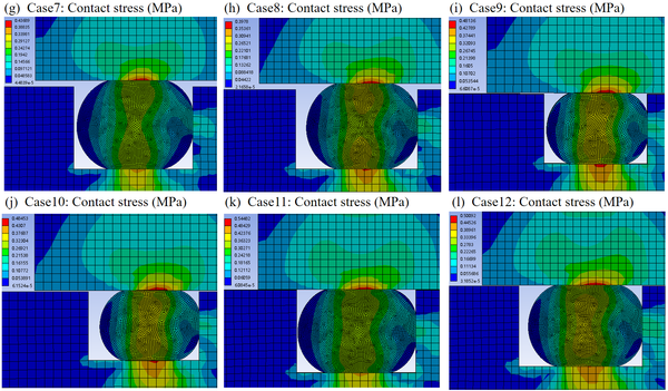
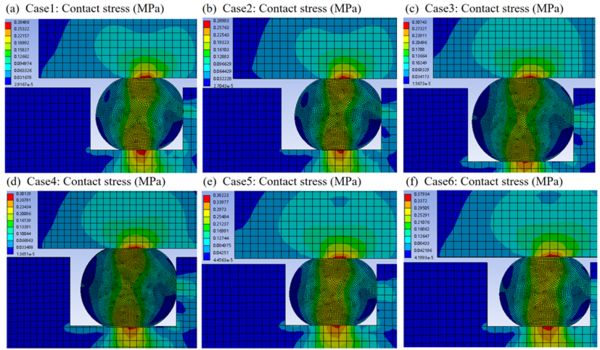
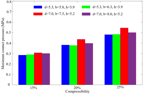
The contact stress distribution of sealing ring and groove under different working conditions is shown in Figure 8, and the corresponding maximum contact stress under different working conditions is shown in Figure 9.
|
| Figure 8. Stress distribution diagram of sealing system under different working condition |
From Figure 8, it can be obtained that the sealing ring compression rate, sealing ring diameter, sealing groove width and depth have a sensitive nonlinear relationship on the contact stress, especially the sealing ring compression rate has a significant impact on the sealing performance of diaphragm compressor. With the same sealing ring and groove structure, the contact pressure between the sealing ring and groove increases significantly with the increasing compression rate. With the increase of compression ratio by 20% and 25%, the contact pressure increased by 42.0% and 77.5%, respectively. From Figure 9, it can be concluded that for the sealing ring with diameter of 5.3mm, the contact pressure changes slightly when the seal groove width is appropriately increased without changing the seal groove depth. However, for the sealing ring with diameter of 7.0 mm, the contact pressure decreases significantly when the sealing groove width is increased, especially at high compression rate. At %, mm, the maximum contact pressure is reduced by 8.1% by increasing the groove width by 0.5 mm. Therefore, at the same compression rate of the sealing ring, the contact pressure at the sealing interface increases with the increase of the diameter of the seal ring, and the structural size of the sealing groove has a significant nonlinear impact on the contact pressure of the large-diameter sealing ring.
|
| Figure 9. Stress distribution diagram of sealing system under different working condition |
4. Conclusions
Based on the typical bolted seal structure of diaphragm compressor in hydrogen refueling station, the numerical simulation model of diaphragm compressor sealing system dynamics and seal contact was established by considering the sudden impact load, assembly process parameters and sealing system structure size. The dynamic mechanical characteristics and sealing performance of diaphragm compressor were obtained, which provided theoretical support for the improved design and selection of diaphragm compressor sealing system. The main conclusions are as follows:
(1) The numerical simulation model of the dynamics and sealing performance of the compressor sealing system considering the structural dimensions and assembly process parameters was established. The modal frequencies of the system under different bolted states were studied, and the typical characteristics of modal changes were obtained, which provided the basis for the bolted state detection and fault diagnosis of the sealing system.
(2) Based on the numerical simulation model of diaphragm compressor sealing performance, the influence of sealing ring compression rate, sealing ring diameter, and sealing groove structure on the sealing performance of diaphragm compressor was obtained. The compression rate of the sealing ring has a significant impact on the sealing performance of the diaphragm compressor. As the compression rate increases by 20% and 25%, the contact pressure increases by 42.0% and 77.5%, respectively. When the compression rate is 25%, for a sealing ring with the diameter of 7.0mm, an increase of 0.5mm in groove width results in a decrease of 8.1% in maximum contact pressure. For the selection of large-diameter sealing rings and the design of sealing groove structures, it is necessary to comprehensively analyze the significant effects of sealing ring compression rate and sealing groove width on the contact pressure of the sealing interface, providing a design basis for improving sealing performance.
Acknowledgements
The work was supported by Key Science and Technology Project in Henan Province (221100240200), Chinese Postdoctoral Science Foundation (2023M733196), Henan Provincial Department of Science and Technology Research Project (232102241030&222102240028), and by Key Science and technique R&D Program of Henan Province (212102210275).
References
[1] Wilberforce T., El-Hassan Z., Khatib F.N., Al-Makky A., Baroutaji A., Carton J.G., Olabi A.G. Developments of electric cars and fuel cell hydrogen electric cars. International Journal of Hydrogen Energy, 42(40):25695-25734, 2017.
[2] Kang J.E., Brown T., Rockers W.W., Samuelsen G.S. Refueling hydrogen fuel cell vehicles with 68 proposed refueling stations in California: Measuring deviations from daily travel patterns. International Journal of Hydrogen Energy, 39(7):3444-3449, 2014.
[3] Wang Y., Xin D., Feng J., Peng X. Research on sealing performance and self-acting valve reliability in high-pressure oil-free hydrogen compressors for hydrogen refueling stations. International Journal of Hydrogen Energy, 35(15):8063-8070, 2010.
[4] Weinert J.X., Liu S., Ogden J.M., Ma J. Hydrogen refueling station costs in Shanghai. International Journal of Hydrogen Energy, 32(16):4089-4100, 2007.
[5] Wang T., Tang Z., Jia X. Study on the stress and deformation of a diaphragm compressor cylinder head under extreme conditions. IOP Conference Series Materials Science and Engineering, 604:012029, 2019.
[6] Wang T., Jia X., Li X., Ren S., Peng X. Thermal-structural coupled analysis and improvement of the diaphragm compressor cylinder head for a hydrogen refueling station. International Journal of Hydrogen Energy, 45(1):809-821, 2020.
[7] Jia X., Zhao Y., Chen J., Peng X. Research on the flowrate and diaphragm movement in a diaphragm compressor for a hydrogen refueling station. International Journal of Hydrogen Energy, 41(33):14842-14851, 2016.
[8] Ren S., Jia X., Jiang J., Peng X. Effect of hydraulic oil compressibility on the volumetric efficiency of a diaphragm compressor for hydrogen refueling stations. International Journal of Hydrogen Energy, 47(1):15224-15235, 2022.
[9] Li J., Liang L., Jia X., Peng X. A new generatrix of the cavity profile of a diaphragm compressor. Proceedings of the Institution of Mechanical Engineers Part C: Journal of Mechanical Engineering Science, 228(10):1754-1766, 2014.
[10] Hu Y., Xu X., Wang W. A new cavity profile for a diaphragm compressor used in hydrogen fueling stations. International Journal of Hydrogen Energy, 42(38):24458-24469, 2017.
[11] Borden K. PDC Machines grows as the world turns to hydrogen. CompressorTech Two: Dedicated to Gas Compression Products and Applications, 4(27), 2022.
[12] Mohith S., Navin Karanth P., Kulkarni S.M. Analysis of annularly excited bossed diaphragm for performance enhancement of mechanical micropump. Sensors and Actuators A: Physical, 335:113381, 2022.
[13] Jia X., Chen J., Wu H., Peng X. Study on the diaphragm fracture in a diaphragm compressor for a hydrogen refueling station. International Journal of Hydrogen Energy, 41(15):6412-6421, 2016.
[14] Liu X., Tian J., Chen R., Jian J. Fluid characteristics analysis and structure optimization in diaphragm compressor. Third International Conference on Mechanical Design and Simulation, SPIE, 12639:863-873, 2023.
[15] Solovev M., Leonhardt A., Graf A., Kunke A., Kräusel V. Development of geometry variants and forming technology for metal diaphragms to increase the efficiency of diaphragm compressor. IOP Conference Series: Materials Science and Engineering, IOP Publishing, 1284(1):012009, 2023.
[16] Bayrak G. Wavelet transform-based fault detection method for hydrogen energy-based distributed generators. International Journal of Hydrogen Energy, 43(44):20293-20308, 2018.
[17] Li X., Chen J., Wang Z., Jia X., Peng X. A non-destructive fault diagnosis method for a diaphragm compressor in the hydrogen refueling station. International Journal of Hydrogen Energy, 44(44):24301:24311, 2019.
[18] Ren S., Jia X., Zhang J., Li X., Zhang S., Peng X. Diagnosis method to identify diaphragm state of diaphragm compressors for hydrogen refueling stations based on dynamic oil pressure. International Journal of Hydrogen Energy, 49, Part D:1043-1055, 2024.
[19] Wang Y., Brubaker K. Multi-objective model auto-calibration and reduced parameterization: Exploiting gradient-based optimization tool for a hydrologic model. Environmental Modelling & Software, 70:1-15, 2015.
[20] Wang Y., Xue C., Jia X., Peng X. Fault diagnosis of reciprocating compressor valve with the method integrating acoustic emission signal and simulated valve motion. Mechanical systems and signal Processing, 56-57:197-212, 2015.Document information
Published on 19/12/23
Accepted on 07/11/23
Submitted on 07/10/23
Volume 39, Issue 4, 2023
DOI: 10.23967/j.rimni.2023.11.002
Licence: CC BY-NC-SA license
Share this document
claim authorship
Are you one of the authors of this document?
