m (Marherna moved page Review 961334110936 to Esnaola et al 2023a) |
|||
| (3 intermediate revisions by one other user not shown) | |||
| Line 149: | Line 149: | ||
<div class="center" style="width: auto; margin-left: auto; margin-right: auto;"> | <div class="center" style="width: auto; margin-left: auto; margin-right: auto;"> | ||
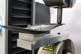
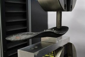
| − | Figure 3. Set-up for the | + | Figure 3. Set-up for the heel (a), and for the hallux (b) bending tests.</div> |
=3. Results= | =3. Results= | ||
| Line 167: | Line 167: | ||
<div class="center" style="width: auto; margin-left: auto; margin-right: auto;"> | <div class="center" style="width: auto; margin-left: auto; margin-right: auto;"> | ||
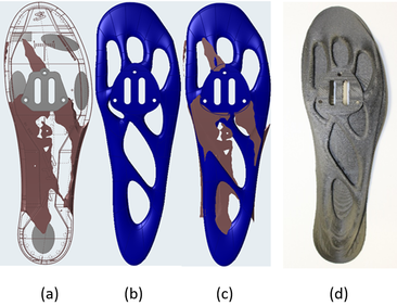
| − | Figure 4. Embodiment design obtained from the topology optimisation (a), parametrised detail design (b), superposition of both (c) and the final 3D printed sole.</div> | + | Figure 4. Embodiment design obtained from the topology optimisation (a), parametrised detail design (b), superposition of both (c) and the final 3D printed sole (d).</div> |
==3.2. Manufacturing== | ==3.2. Manufacturing== | ||
| Line 224: | Line 224: | ||
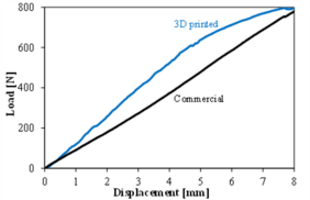
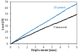
Figure 5. Force-displacement curves for the commercial and 3D printed soles when the pressure is applied on the hallux (a) and on the heel (b).</div> | Figure 5. Force-displacement curves for the commercial and 3D printed soles when the pressure is applied on the hallux (a) and on the heel (b).</div> | ||
| − | The quantitative comparison of the performances supports the suitability of the new sole. The mass (''m''), stiffness (''S''), and specific stiffness (''S''<sub>s</sub>) of both soles are shown in Table | + | The quantitative comparison of the performances supports the suitability of the new sole. The mass (''m''), stiffness (''S''), and specific stiffness (''S''<sub>s</sub>) of both soles are shown in Table 4. The 3D printed sole is a 17% lighter, but it must be considered that the insole is also integrated (8 g), while in the commercial sole it is not. Thus, the real weight reduction is even higher. Even though this sole is lighter, its stiffness is a 40% higher in the hallux and a 35% higher in the heel. The differences are even higher when specific stiffnesses are compared, being the new sole a 69% stiffer at the hallux and a 64% in the heel. |
<div class="center" style="width: auto; margin-left: auto; margin-right: auto;"> | <div class="center" style="width: auto; margin-left: auto; margin-right: auto;"> | ||
| − | Table | + | Table 4. Mass (''m''), stiffness (''S'') and specific stiffness (''S<sub>S</sub>'') of both soles</div> |
{| style="width: 100%;border-collapse: collapse;" | {| style="width: 100%;border-collapse: collapse;" | ||
Latest revision as of 11:11, 5 December 2023
Abstract.
Customised cycling soles are extremely complex to design and manufacture since the plantar pressure distribution and anatomical shape are specific for every foot. This paper explores the potential of topology optimisation and additive manufacturing of continuous fibre reinforced plastic. The highly abstract material distribution resulting from the topology optimization software was interpreted considering the additive manufacturing constraints for getting the detailed design. The selected printing strategy consisted of concentric fibre orientation to better fit load-paths, and the build-orientation aimed to maximise the fibre content, resulting in 30 hours for printing each sole. Regarding the specific stiffness at the hallux and the hell, the new soles are at least 60% higher. Therefore, it has been confirmed that the proposed approach is a powerful tool to design the cycling shoe adapted to the local stiffness of each foot.
KEYWORDS: 3D printing, Continuous Fibre Reinforced Plastic, Topology Optimisation, Design for Additive Manufacturing
1. Introduction
The continuous improvement in people’s living standards, in combination with other social trends such as customisation and prosumption [1], as well as the pressure for adopting the principles of the Circular Economy [2], have dramatically changed the sport equipment market. As consumers have an increasing desire to buy unique products with innovative technologies that precisely reflect their individual preferences and needs, with higher comfort and beauty standards, the competitive advantage of firms is shifting from the manufacturing and supply chain capabilities to the design capabilities [3]. In cycling, as the foot–pedal interface is the only direct site for energy transfer from the cyclist to the bicycle, and there are high reactive and repetitive forces on a small contact area of around 60 mm2, the high plantar pressures generated contribute to foot and ankle injuries [4]. Custom Made Insoles (CMIs), by distributing the plantar pressure over a larger surface area, aim to prevent or treat many foot pathologies [4,5]. Currently, a great amount of cycling-specific carbon fibre composite CMIs are available in the market [6]. Traditional methods based on manufacturing a plaster cast mould are still employed by many podiatrists, but they involve lengthy lead-times and are comparatively expensive.
The applications of Additive Manufacturing (AM) techniques, and more specifically extrusion-based AMs, are economically viable for producing personalised sports footwear [7]. AM is a digital manufacturing technique that enables what is called an “economy-of-one” [8] and has the potential to disrupt even relatively mature markets. In fact, offering functionally optimised products tailored to the customers' needs, producers will be able to demand a price premium compared to non-customized products [9]. The current shoe manufacturing model is based on offshore and centralised facilities for mass productions of identical products to supply a global market, but AM can lead the transition to a cloud-based and geographically distributed manufacturing systems, where customised products are produced on demand and near to the place of consumption [8] with lower environmental impact [2]. Distributed manufacturing based on AM can be enhanced by the multi-users platforms, such as the Smart Prescription Platform (SPP) [10], that cover the whole CMI development phases, integrating all the technologies (3D scanners, baropodometric platforms, footwear virtual catalogues, plantar pressure simulators, Augmented Reality devices, 3D CAD systems, AM), and ensuring an fully electronic dataflow among the tools. Although AM has much potential in the footwear field and has already been successful in creating sprint shoes and insoles [7], it is often argued that mechanical properties of materials are still limited [11]. However, this has changed recently since there are a number of extrusion systems on the market capable of printing with continuous fibre composite materials [12].
Customisation of cycling footwear based on individual anthropometry and pathological conditions is extremely complex due to their organically shaped, but several authors have proposed design methods adapted to AM [13], including topology optimisation [14]. Through topology optimisation, the volumes that contribute least mechanically in the design space can be identified and removed in an iterative process until a load-compatible structural topology is achieved.
The objective of the present paper is to design and validate a 3D printed customised cycling shoe. The product has been designed using topology optimisation for a complex plantar pressure distribution and with the stiffness of a commercial cycling shoe as target. The bending stiffness at the hallux and the heel have been characterised and compared with those of the commercial shoe.
2. Methodology
2.1. Materials and manufacturing
A Mark Two® 3D printer from Markforged has been employed for manufacturing the prototypes. The printer has two extruders, systems, one for printing the construction material and another one for printing the reinforcement material. The construction material (Onyx®) is made from combining tough polyamide with micro-carbon reinforcement. The first layer of every printed part is a 125 µm Onyx® layer, which makes the laying of the CFRP on the printing bed easier and also avoids the damage when the sample is removed. For symmetry reasons, a final Onyx® layer is also added on the top of the samples. The reinforcement material is a pre-impregnated polyamide reinforced with continuous carbon fibres form Markforged. Each reinforcement layer thickness is 125 µm. The main properties of the 3D printed continuous fibre composites [15], as well as of the injection moulded PA66 reinforced with a 33% of glass fibres used in the reference sole are reported in Table 1.
| Material | Young’s modulus
[GPa] |
Tensile strength
[MPa] |
Poisson's ratio | Density
[g/cm3] |
| 3D printed composite | 69.4* | 905* | 0.41* | 1.25* |
| Injection moulded composite** | 8.3 | 150 | 0.35 | 1.36 |
*Parallel to the fibres
**Data provided by Spiuk
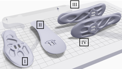
The feasibility and performance of a 3D printed product is highly dependent on its build orientation, and must be selected based on many relevant variables, including manufacturing time; local roughness; necessity and location of support structures; and fibre orientations. The build-orientation study comprised four alternatives (Fig. 1).
2.2. Design method
The formal design process applied included phases of design specifications, where the problem is formally defined in terms of the associated constraints and objectives; embodiment design, which consists of the generation and evaluation of high-level solutions to the problem definition; and detail design, where the preferred solution is formally specified to enable manufacture.
2.2.1. Design specifications
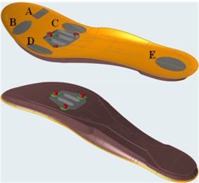
The main function of the sole is to sustain the plantar pressure without failure, with a specific stiffness equal or higher than that of the Spiuk Aldama Road shoe (size 43). The used plantar pressure is based on the findings of Henning and Sanderson [16] for a cadence of 80 rpm at 400 W and a crank angle of 90°, whereas the area of each contact zone has been taken from literature [4] (Fig. 2). The sole was clamped on the clipless pedal at the three central points of the mid forefoot. The five contact zones, as well as the clipless fixing zone and the 1 mm thick insole, were defined as functional, and the design space enveloped the sole and insole of the commercial shoe. The applied pressure and contact area of each zone are reported in Table 2.
| Zone | Pressure [kPa] [16] | Contact area [mm2] [4] |
| (A) Hallux | 464 | 230 |
| (B) Toes | 95 | 470 |
| (C) Medial forefoot | 314 | 505 |
| (D) Lateral forefoot | 146 | 470 |
| (E) Heel | 80 | 645 |
2.2.2. Embodiment design
Based on the aforementioned specifications, an idealised embodiment design was defined using Altair InspireTM software. Taking as reference the ratio between the bending specific stiffness of the injection moulded composite and the 3D printed one, the topology optimisation was performed with the objective of minimising the mass a 75%. A minimum wall thickness of 9.6 mm was defined as a constraint of design for additive manufacturing, this value was experimentally determined and will be justified in the 3.1.1 section. Due to the fact the topological optimisation assumed isotropic material properties, it is not a perfect analogy for 3D printed composites reinforced with continuous fibres. However, as the load case of the shoe is close to pure bending and fibres will be preferentially oriented perpendicular to the bending moment, the material will be modelled as an isotropic material (Table 1).
2.2.3. Detail design
Once the design embodiment phase was formalised, a discretized representation of the optimized material distribution was generated, the design details of the parametrised geometry were then defined with PolyNurbs. The geometry of the commercial insole was integrated with the customised sole in order to manufacture the product in one-step.
3. Bending tests
The shoes were clamped to the test fixture by screws at the three central points of the mid forefoot. Two bending tests have been carried out: the first applying a downward force on the heel (Fig. 3a), and the second applying the downward force on the hallux zone (Fig. 3b). Bending tests were carried out using a Hoyton/HM-D universal testing machine equipped with a 100 kN load cell. The overall displacement was registered from the encoder of the ball-screw. The crosshead speed was 10 mm/min and before testing, the soles were conditioned for 48 hours at 23 ºC and 55% RH, the same conditions than for the bending tests.
(a) |
(b) |
3. Results
3.1. Design of the sole
3.1.1. Manufacturing constraints
Topology optimisation software, in absence of any geometrical restriction, tends towards lattice-like structures with many thin walls, where 3D printer is rarely able for laying down the continuous-fibre reinforced strands. Additionally, as the contour wall is mandatory to be printed with Onyx®, the amount of fibre depends on the section area parallel to the printing bead. Therefore, the smallest feature size should be set to guarantee the presence of a minimum amount of carbon fibre reinforced composite. For this purpose, the amount of carbon fibre strand laid down into discs with different diameter and printing toolpath has been analysed with Eiger®. The results showed that concentric printing paths introduced always more fibre than the isotropic one, and the fibre content increased with the disc diameter. In fact, the smallest disc diameter reinforced with fibre was 8.6 mm for the concentric strategy, whereas isometric did not lay down strands with fibre until 9.6 mm. Therefore, a minimum wall thickness of 9.6 mm was selected as design rule.
3.1.2. Topology optimisation and detail design
The geometrical representations of the embodiment design (Fig. 4a) and the detail design (Fig. 4b), as well as the superposition of both (Fig. 4c), help understanding the followed design method. The result of topology optimization was a rough material distribution that was not a ready-to-use model, but it served as inspiration during the detail design. As can be observed, the material distribution does not follow a continuous pattern. The toes zone and lateral forefoot zone are isolated. Apparently, the stiffness of the insole is enough for supporting the plantar pressure on these zones. The hallux, which has been identified as a high-pressure zone [4,16], is fixed to the pedal zone with a rib and with a weak connection to the medial forefoot. A strong rib between the clamped zone and the heel through the medial is suggested. However, even if a material rib comes out of pedal zone through the lateral, it is not connected to the heel. The most important modification has been to close the sole-contour with a continuous ring, generating a direct load-path between all the plantar pressure zones. As a second design criterion, the toes and the lateral forefoot have been connected to the pedal zone by ribs. Regarding the lateral rib at the midfoot, it has been slightly shifted to confluence with the medial one at the same point. The rib connecting the lateral and medial between the clamping zone and the heel has been widened to support torsional loads. Finally, a wide frontal area has been designed for the toes, but it is more an aesthetic than a structural strategy. In all cases, a minimum width of 9.6 mm and wall thicker than 2 mm were respected to guarantee the presence of a minimum amount of reinforcing fibres.
3.2. Manufacturing
The selection of the build-orientation was based on the printing time, the amount and the orientation of the fibre embedded in the sole, the support structure, as well as the ease to remove it. The results obtained with Eiger® are shown in the Table 3. As a rule, printing time is minimised selecting the build orientation with the lowest height (orientations I and II), but in the case of the sole they need almost four times more supports and the resulting printing times are similar to the orientations with the highest height (orientations III and IV). Regarding the structural behaviour of the sole, the amount of embedded fibre with the I and II orientations is a 74% higher, and their interlayer area, typical weak point of 3D printed parts, is also bigger. When screening between I and II, the placement of the supports has been decisive since their position affects the part quality and the ease for remove. Based on these criteria, the orientation I has been selected, since the supports are on the relatively flat surface of the insole and the marks are not visible.
| Build-orientation | Printing time [h] | Fibre-reinforced strand [cm3] | Support [cm3] |
| I | 30 | 47.1 | 94.3 |
| II | 31 | 47.2 | 86.7 |
| III | 31 | 27.1 | 26.1 |
| IV | 28 | 27.0 | 22.7 |
3.3. Validation
The bending behaviour of the commercial and 3D printed soles are shown in the Fig. 5. The front of the 3D printed sole is stiffer (Fig. 5a) and behaved linearly up to 5 mm of displacement. The loss of its linearity was not associated to plasticity since the sole recovered its original position when unloaded. The commercial sole presented a linear behaviour up to the imposed 8 mm displacement. The comparison of the stiffness when the load was applied on the heel (Fig. 5b) also revealed that the 3D printed sole is stiffer (Fig. 5b), and that both soles behaved linearly. Finally, it can be concluded that the lack of fibres detected does not weak the new sole.
|
|
| (a) | (b) |
The quantitative comparison of the performances supports the suitability of the new sole. The mass (m), stiffness (S), and specific stiffness (Ss) of both soles are shown in Table 4. The 3D printed sole is a 17% lighter, but it must be considered that the insole is also integrated (8 g), while in the commercial sole it is not. Thus, the real weight reduction is even higher. Even though this sole is lighter, its stiffness is a 40% higher in the hallux and a 35% higher in the heel. The differences are even higher when specific stiffnesses are compared, being the new sole a 69% stiffer at the hallux and a 64% in the heel.
| Hallux | Heel | ||||
| m [g] | S [N/mm] | Ss [N/mm·g] | S [N/mm] | Ss [N/mm·g] | |
| Commercial | 104 | 93 | 0.9 | 6.2 | 0.06 |
| 3D printed | 86 | 130 | 1.5 | 8.4 | 0.1 |
4. Conclusions
The most relevant contribution of the present paper is that the customised design of a 3D printed cycling sole has been implemented for the first time. Topology optimization has been proved to be efficient in identifying rough designs adapted to an individualised plantar pressure. However, a refinement of the local geometry had to be done incorporating criteria related to design for additive manufacturing of continuous carbon fibre reinforced polyamide composites.
From the performance point of view, the specific stiffness of the 3D printed sole can be at least 60% higher, and thanks to the design freedom the local stiffness can be adapted to the pressure at the hallux, the toes, the forefoot, the midfoot, and the heel zones.
Regarding the lead-time, once the plantar pressure and scanned foot of the bicycle rider are received, less than 8 hours are necessary to get the detail design, and a day and a half to manufacture each sole. The customisation is not limited to the stiffness of the sole, as the insole can be integrated, reducing the cost and shortening the lead-time of the whole cycling shoe.
Acknowledgements
The authors thank SPIUK and the Basque Government (Grant No. IT1613-22) for providing financial support funding this project. The authors also thank K. Etxeberria and D. Aguilar for their contribution to the sole design, as well as A. Ena from IDAERO for his support with Altair InspireTM.
References
[1] S. Ford, M. Despeisse. Additive manufacturing and sustainability: an exploratory study of the advantages and challenges. Journal of Cleaner Production 137 (2016) 1573–1587.
[2] M. Moreno, C. Turner, A. Tiwari, W. Hutabarat, F. Charnley, D. Widjaja, L. Mondini. Re-distributed manufacturing to achieve a Circular Economy: A case study utilizing IDEF0 modeling. Procedia CIRP 63 (2017) 686–691.
[3] R. Jiang, R. Kleer, F.T. Piller. Predicting the future of additive manufacturing: A Delphi study on economic and societal implications of 3D printing for 2030. Technological Forecasting & Social Change 117 (2017) 84–97.
[4] J.A. Bousie, P. Blanch, T.G. McPoil, Bill Vicenzino. Hardness and posting of foot orthoses modify plantar contact area, plantar pressure, and perceived comfort when cycling. Journal of Science and Medicine in Sport 21 (2018) 691–696.
[5] B.C. O’Neill, K. Graham, M. Moresi, P. Perry, Donald Kuah. Custom formed orthoses in cycling. Journal of Science and Medicine in Sport 14 (2011) 529–534.
[6] M. Koch, M. Fröhlich, E. Emrich, A. Urhausen, The impact of carbon insoles in cycling on performance in the Wingate Anaerobic Test. J Sci Cycling 2 (2013) 2–5.
[7] V. Manoharan, S.M. Chou, S. Forrester, G.B. Chai, P.W. Kong. Application of additive manufacturing techniques in sports footwear. Virtual and Physical Prototyping 8 (2013) 249–252.
[8] E. Rauch, M. Unterhofer, P. Dallasega. Industry sector analysis for the application of additive manufacturing in smart and distributed manufacturing systems. Manufacturing Letters 15 (2018) 126–131.
[9] C. Weller, R. Kleer, F.T. Piller. Economic implications of 3D printing: Market structure models in light of additive manufacturing. Int. J. Production Economics 164 (2015) 43–56.
[10] M. Mandolini, A. Brunzini, M. Germani, A collaborative web-based platform for the prescription of Custom-Made Insoles. Advanced Engineering Informatics 33 (2017) 360–373.
[11] A.S. Salles, D.E. Gyi. Delivering personalised insoles to the high street using additive manufacturing. International Journal of Computer Integrated Manufacturing 26 (2013) 386–400.
[12] G.D. Goh, V. Dikshit, A.P. Nagalingam, G.L. Goh, S. Agarwala, S.L. Sing, J.Wei, W.Y. Yeong. Characterization of mechanical properties and fracture mode of additively manufactured carbon fiber and glass fiber reinforced thermoplastics. Materials and Design 137 (2018) 79–89.
[13] M. Davia-Aracil, A. Jimeno-Morenilla, F. Salas. A new methodological approach for shoe sole design and validation. Int J Adv Manuf Technol 86 (2016) 3495–3516.
[14] T. Nishiwaki, M. Nonogawa. Application of topological optimization technique to running shoe designing. Procedia Engineering 112 (2015) 314–319.
[15] M. Iragi, C. Pascual-González, A. Esnaola, C.S. Lopes, L. Aretxabaleta. Ply and interlaminar behaviours of 3D printed continuous carbon fibre reinforced thermoplastic laminates; effects of processing conditions and microstructure. Additive Manufacturing 30 (2019) 100884.
[16] Hennig E., Sanderson D.J. In-shoe pressure distributions for cycling with two types of footwear a different mechanical loads. J Appl Biomechanics 11 (1995) 68-80.
Document information
Published on 25/09/24
Accepted on 04/12/23
Submitted on 17/05/23
Volume 08 - COMUNICACIONES MATCOMP21 (2022) Y MATCOMP23 (2023), Issue Núm. 6 - Fabricación y Aplicaciones Industriales, 2024
DOI: 10.23967/r.matcomp.2024.06.03
Licence: Other
Share this document
Keywords
claim authorship
Are you one of the authors of this document?
