(→4.2.2 Influence of feed particle size on morphological characteristics of crushed rock) |
(→References) |
||
| (11 intermediate revisions by 2 users not shown) | |||
| Line 198: | Line 198: | ||
A series of indexes for evaluating the two-dimensional shape parameters of particles have been used in previous research [15-16]. | A series of indexes for evaluating the two-dimensional shape parameters of particles have been used in previous research [15-16]. | ||
| − | Ye [17] selected three representative particle shape evaluation parameters for research. The length-width ratio, flatness, and sphericity can sensitively reflect the degree of deviation from spherical particles and can be preferentially used as particle shape evaluation parameters. | + | Ye Jiabing et al.[17] selected three representative particle shape evaluation parameters for research. The length-width ratio, flatness, and sphericity can sensitively reflect the degree of deviation from spherical particles and can be preferentially used as particle shape evaluation parameters. |
===3.4 Angularity=== | ===3.4 Angularity=== | ||
| Line 548: | Line 548: | ||
Through [[#img-20|Figures 20]], [[#img-22|22]] and [[#img-24|24]], the analysis of the previous figures, under extrusion, the parameters of gray‒green rock after crushing change obviously starting at a particle size of 9.5mm-16mm; the angularity rises, and the roundness and overall profile coefficient decrease. When the particle size of limestone is 9.5mm-16mm, the trend is opposite to that of limestone, and the angularity increases, while the roundness and overall profile coefficient decrease. The overall profile coefficient of granite decreases from 0.6582 to 0.6516 at a grain size of 9.5mm-16mm, and the angularity decreases from 1.0420 to 1.0398. However, the corresponding roundness rises sharply from 2.15 to 2.39.Due to the limitation of experimental conditions, the current research hopes to comprehensively utilize machine vision and advanced processing software to help the development of particle breakage. | Through [[#img-20|Figures 20]], [[#img-22|22]] and [[#img-24|24]], the analysis of the previous figures, under extrusion, the parameters of gray‒green rock after crushing change obviously starting at a particle size of 9.5mm-16mm; the angularity rises, and the roundness and overall profile coefficient decrease. When the particle size of limestone is 9.5mm-16mm, the trend is opposite to that of limestone, and the angularity increases, while the roundness and overall profile coefficient decrease. The overall profile coefficient of granite decreases from 0.6582 to 0.6516 at a grain size of 9.5mm-16mm, and the angularity decreases from 1.0420 to 1.0398. However, the corresponding roundness rises sharply from 2.15 to 2.39.Due to the limitation of experimental conditions, the current research hopes to comprehensively utilize machine vision and advanced processing software to help the development of particle breakage. | ||
| − | <div id='img- | + | <div id='img-19'></div> |
{| class="wikitable" style="margin: 0em auto 0.1em auto;border-collapse: collapse;width:auto;" | {| class="wikitable" style="margin: 0em auto 0.1em auto;border-collapse: collapse;width:auto;" | ||
|-style="background:white;" | |-style="background:white;" | ||
| − | |||
| − | |||
| − | |||
| − | |||
| − | |||
| − | |||
| − | |||
|style="text-align: center;padding:10px;"| [[File:Image24.png|276x276px]] | |style="text-align: center;padding:10px;"| [[File:Image24.png|276x276px]] | ||
| − | |||
|- | |- | ||
| style="background:#efefef;text-align:left;padding:10px;font-size: 85%;"| '''Figure 19'''. Gray‒green rock shear | | style="background:#efefef;text-align:left;padding:10px;font-size: 85%;"| '''Figure 19'''. Gray‒green rock shear | ||
| − | |||
| − | |||
| − | |||
| − | |||
| − | |||
| − | |||
| − | |||
| − | |||
|} | |} | ||
| − | |||
| − | |||
| − | |||
| − | |||
| − | |||
| − | |||
| − | + | <div id='img-20'></div> | |
| − | + | ||
| − | + | ||
| − | + | ||
| − | + | ||
| − | + | ||
| − | + | ||
| − | + | ||
| − | + | ||
| − | + | ||
| − | + | ||
| − | + | ||
| − | + | ||
| − | + | ||
| − | + | ||
| − | + | ||
| − | + | ||
| − | + | ||
| − | + | ||
| − | + | ||
| − | + | ||
| − | <div id='img- | + | |
{| class="wikitable" style="margin: 0em auto 0.1em auto;border-collapse: collapse;width:auto;" | {| class="wikitable" style="margin: 0em auto 0.1em auto;border-collapse: collapse;width:auto;" | ||
|-style="background:white;" | |-style="background:white;" | ||
| − | |style="text-align: center;padding:10px;"| | + | |style="text-align: center;padding:10px;"| [[File:Image25.png|258x258px]] |
|- | |- | ||
| − | | style="background:#efefef;text-align:left;padding:10px;font-size: 85%;"| '''Figure | + | | style="background:#efefef;text-align:left;padding:10px;font-size: 85%;"| '''Figure 20'''. Gray‒greenstone extrusion |
|} | |} | ||
| − | <div id='img- | + | <div id='img-21'></div> |
{| class="wikitable" style="margin: 0em auto 0.1em auto;border-collapse: collapse;width:auto;" | {| class="wikitable" style="margin: 0em auto 0.1em auto;border-collapse: collapse;width:auto;" | ||
|-style="background:white;" | |-style="background:white;" | ||
| − | |style="text-align: center;padding:10px;"| | + | |style="text-align: center;padding:10px;"| [[File:Image26.png|288x288px]] |
|- | |- | ||
| − | | style="background:#efefef;text-align:left;padding:10px;font-size: 85%;"| '''Figure | + | | style="background:#efefef;text-align:left;padding:10px;font-size: 85%;"| '''Figure 21'''. Limestone shear |
|} | |} | ||
| − | <div id='img- | + | <div id='img-22'></div> |
{| class="wikitable" style="margin: 0em auto 0.1em auto;border-collapse: collapse;width:auto;" | {| class="wikitable" style="margin: 0em auto 0.1em auto;border-collapse: collapse;width:auto;" | ||
|-style="background:white;" | |-style="background:white;" | ||
| − | |style="text-align: center;padding:10px;"| | + | |style="text-align: center;padding:10px;"| [[File:Image27.png|282x282px]] |
|- | |- | ||
| − | | style="background:#efefef;text-align:left;padding:10px;font-size: 85%;"| '''Figure | + | | style="background:#efefef;text-align:left;padding:10px;font-size: 85%;"| '''Figure 22'''. Limestone extrusion |
|} | |} | ||
| − | <div id='img- | + | <div id='img-23'></div> |
{| class="wikitable" style="margin: 0em auto 0.1em auto;border-collapse: collapse;width:auto;" | {| class="wikitable" style="margin: 0em auto 0.1em auto;border-collapse: collapse;width:auto;" | ||
|-style="background:white;" | |-style="background:white;" | ||
| − | |style="text-align: center;padding:10px;"| | + | |style="text-align: center;padding:10px;"|[[File:Image28.png|252x252px]] |
|- | |- | ||
| − | | style="background:#efefef;text-align:left;padding:10px;font-size: 85%;"| '''Figure | + | | style="background:#efefef;text-align:left;padding:10px;font-size: 85%;"| '''Figure 23'''. Granite shear |
|} | |} | ||
| − | <div id='img- | + | <div id='img-24'></div> |
{| class="wikitable" style="margin: 0em auto 0.1em auto;border-collapse: collapse;width:auto;" | {| class="wikitable" style="margin: 0em auto 0.1em auto;border-collapse: collapse;width:auto;" | ||
|-style="background:white;" | |-style="background:white;" | ||
| − | |style="text-align: center;padding:10px;"| | + | |style="text-align: center;padding:10px;"| [[File:Image29.png|264x264px]] |
|- | |- | ||
| − | | style="background:#efefef;text-align:left;padding:10px;font-size: 85%;"| '''Figure | + | | style="background:#efefef;text-align:left;padding:10px;font-size: 85%;"| '''Figure 24'''. Granite extrusion |
|} | |} | ||
| + | ==5. Conclusions== | ||
| − | + | An imaging approach was used to detect the crushing effect of rock particles. The influence of loading mode and feeding particle size on the degree of rock crushing and the influence of rock morphology after crushing are analyzed and the corresponding experimental study is carried out, the main conclusions are as follows: | |
| − | + | ||
| − | + | ||
| − | + | ||
| − | + | ||
| − | + | ||
| − | + | ||
| − | + | (1) Under a shear load, the crushing ratio decreases from 1.881 to 1.772. Under extrusion, the crushing ratio increases from 5.55 to 6.96. | |
| − | + | (2) Under extrusion, the angularity shows an upward trend, with the highest value of 1.04301. Roundness first decreases and then increases with an inflection point of 2.23. The overall profile coefficient first increases and then decreases, and the inflection point is 0.675. Under shear loading, angularity first decreases and then rises with an inflection point of 1.0404. Roundness also decreases first and then increases with an inflection point of 2.03. In contrast, the overall profile coefficient rises first and then falls, showing an approximately symmetrical inflection point of 0.7028. | |
| − | + | (3) Under a shear load, when the inlet particle size is between 9.5mm and 16mm, rocks composed of different materials have obvious differences. Under these conditions, the crushing ratio of limestone is 1.915, and the sand formation rate is 2.89%. Under extrusion, when the inlet particle size is between 9.5mm and 16mm, there are obvious variations between rocks composed of different materials; in particular, when the inlet particle size of granite is between 16mm and 19mm, the crushing ratio is 7.21, and the sand formation rate is 11%. | |
| − | + | (4) The analysis of the morphological characteristics of the broken rock shows that the parameters of granite with a grain size between 9.5mm and 16mm tend to increase: the angularity is 1.055, the roundness is 2.06, and the overall profile coefficient is 0.7001. Under extrusion, rock composed of different materials changes from 9.6mm to 16mm. The angularity, roundness and overall profile coefficient, which have a great influence on the morphological characteristics of broken rock, are 1.046, 2.33 and 1.9, respectively. | |
| − | + | It shows that the image-based detection system for detecting the effect of rock particle breakage has high applicability and credibility, and has the advantages of real-time and stability, which can provide a basis for the follow-up research on intelligent mine construction and equipment optimization, and is worthy of further popularization and application. | |
| − | + | '''Declaration of Competing Interest''' | |
| − | + | The authors certify that they have no affiliations with or involvement in any organization or entity with any financial interest (such as honoraria; educational grants; participation in speakers' bureaus; membership, employment, consultancies, stock ownership, or other equity interest; and expert testimony or patent-licensing arrangements) or nonfinancial interest (such as personal or professional relationships, affiliations, knowledge or beliefs) in the subject matter or materials discussed in this manuscript. | |
| − | + | '''Data Availability''' | |
| + | The data will be provided upon request and can be used without any conflict of interest. | ||
| − | + | ==Acknowledgments== | |
| − | + | This project is funded by Fujian University of Technology for the Fujian University of Technology Science and Technology Project, Project No. GY-Z220201. Agricultural University Industry-University Cooperation Project, Project No. 2020N5015. Key Research and Industrialization Project of Technological Innovation in Fujian Province (University-Enterprise Joint Category), Project No. 2023XQ002. | |
| − | < | + | ==References== |
| + | <div class="auto" style="text-align: left;width: auto; margin-left: auto; margin-right: auto;font-size: 85%;"> | ||
| − | + | [1] Hamzeloo E., Massinaei M., Mehrshad N. Estimation of particle size distribution on an industrial conveyor belt using image analysis and neural networks. Powder technology, 261:185-190, 2014. https://doi.org/10.1016/j.powtec.2014.04.038 | |
| − | + | [2] Chen A.L., Chen B.Z., Feng C.A. Image analysis algorithm and verification for on-line molecular sieve size and shape inspection. Advanced Powder Technology, 25(2):508-513, 2014. https://doi.org/10.1016/j.apt.2013.08.004 | |
| − | + | [3] Jug J., Strelec S., Gazdek M., Kavur B. Fragment size distribution of blasted rock mass. IOP Conference Series: Earth and Environmental Science. IOP Publishing, 95(4):042013, 2017. | |
| − | + | ||
| − | + | [4] Yang J., Chen S. An online detection system for aggregate sizes and shapes based on digital image processing. Mineralogy and Petrology, 111(1):135-144, 2017. https://doi.org/10.1007/s00710-016-0458-y | |
| − | + | ||
| − | + | [5] Zheng J., Hryciw R.D. Soil particle size and shape distributions by stereophotography and image analysis. Geotech. Test. J, 40(2):317-328, 2017. | |
| − | + | ||
| − | + | [6] Shehu S.A., Yusuf K.O., Hashim M.H.M. Comparative study of WipFrag image analysis and Kuz-Ram empirical model in granite aggregate quarry and their application for blast fragmentation rating. Geomechanics and Geoengineering, 17(1):197-205, 2022. | |
| − | + | ||
| − | + | [7] Huang-Yi W., Luo-Jian Y .Study on the crushing mechanism and parameters of the two-flow crusher. Applied Mathematics and Nonlinear Sciences, 7(2):875-890, 2022. https://doi.org/10.2478/amns.2021.2.00172 | |
| − | + | ||
| − | + | [8] Chen H., Tang L., Chen J., Xu X.-R. Study on measurement technique of sediment particle size base on RGB image. Journal of Sediment Research, 01:25-29, 2015. | |
| − | + | ||
| − | + | [9] Yang Y., Wei Z., Chen Y., Ren B. Study on the shapes of tailings particles based on microscopy and image processing technologies. Chin. J. Rock Mechan. Engin, S1:3689-3695, 2017. | |
| − | + | ||
| − | + | [10] Li Z., Ye Y., Tong X., Li K. Study on the mechanism of particle breakage under new composite loads. Journal of Engineering and Technological Sciences, 51(2):231-250, 2019. | |
| − | + | ||
| − | + | [11] Chen J., Zhang Z., Xu W., Li L. Quantitative method of shape parameters of mineral particles based on image processing. Journal of Engineering Geology, 29(1):59-68, 2021. | |
| − | + | ||
| + | [12] Zhang L., Chu M., Deng X., Chen Z. Graph-based detection technology for mineral grains image. Journal of Hefei University of Technology (Natural Science), 44(09):1193-1197+1209, 2021. | ||
| + | |||
| + | [13] Wu M., Wang J. Constitutive modeling of natural sands using a deep learning approach accounting for particle shape effects. Powder Technology, 404:117439, 2022. | ||
| + | |||
| + | [14] Höving S., Neuendorf L., Betting T., Kockmann N. Determination of particle size distributions of bulk samples using micro-computed tomography and artificial intelligence. Materials, 16(3):1002, 2023. | ||
| + | |||
| + | [15] Lin Y., Wu M., Wang P. Field test and analysis of multiple vibration-damped track structures for 120 km/h subway. Railway Standard Design, 62(02):67-71, 2018. | ||
| + | |||
| + | [16] Guan Z., He Y., Gao X., Den T. 2D shape characteristic and the clump reconstruction of gravel particle in granite residual soil. Journal of Water Resources and Architectural Engineering, (04):4-10, 2021. | ||
| + | |||
| + | [17] Ye J., Zhang J., Zou W. Influences of grain shape on pore characteristics of filled breakstone aggregate. Rock and Soil Mechanics, 39(12):4457-4467, 2018. | ||
Latest revision as of 10:24, 14 November 2023
Abstract
When maging is used to detect the crushing effect of rock particles, the selected characterization parameters are important factors affecting the results. The image-based detection system is composed of three parts: an image acquisition system, a storage platform, and a digital image processing system.The influence of loading mode and feeding particle size on rock crushing degree and rock morphology characteristics after crushing are analyzed respectively; The crushing ratio and sand-forming ratio of limestone, limestone and granite under shear and extrusion loads are analyzed. The experimental results show that the crushing ratio and sand formation rate play a key role in the crushing of rocks composed of different materials under shear compression loading. The effect analysis of crushing under the feed particle size of 9.5 mm to 16mm shows that there is a great correlation between edges and corners, roundness and overall contour. It provides a basis for the follow-up research on intelligent mine construction and equipment optimization, and is worthy of further popularization and application.
Keywords: Image processing, rock particles, crushing effect parameters, loading mode, feed particle size
1. Introduction
As one of the most important building materials, sand and gravel aggregate is widely used in building engineering and represents a large proportion of the solid materials used in construction in China. To obtain qualified products, it is necessary to carry out quality inspection on broken aggregate, but traditional inspection methods are mostly manual or semimanual, which are complicated and inefficient and will make the corresponding inspection results inaccurate. Therefore, it is necessary to use new methods to analyze broken rock particles.
Hamzeloo et al. [1] used image processing and neural network technology to estimate the particle size distribution in the crushing circuit of a copper concentrator. Chen et al. [2] proposed an online machine-based visual inspection method for feedback control of molecular sieve growth in drum granulation. A comparison with micrometer measurements confirmed the accuracy of this approach. Jug et al. [3] compared simulated debris with actual postexplosion debris through image processing and developed and calibrated a debris model.
Yang et al. [4] proposed an online detection system based on size and shape that can realize the noncontact measurement of related attributes of objects with high reliability. Zheng et al. [5] proposed a particle size characterization method based on three-dimensional photography that can accurately determine the thickness of particles. Shehu et al. [6] analyzed the particle size distribution of granite aggregate in a quarry by using scanning digital image processing software and the Kuz-Ram empirical model and realized the preliminary evaluation of the blasting design. Wu et al. [7] used the discrete element method to analyze the energy changes in the crushing process. Chen et al. [8] adopted RGB image processing to improve the gray level and edge gray gradient of particle images. Yang et al. [9] used microscopic and image processing technology to quantitatively analyze river sand and sea sand for construction.
Li et al. [10] proposed a new particle breakage model and then analyzed the particle breakage mechanism. Chen et al. [11] realized the quantitative analysis of mineral particle morphology by using the image method. Zhang Li et al. [12] proposed a new image segmentation method based on graphs that can extract more objects and achieve high accuracy. Wu and Wang [13] proposed a deep learning model for predicting the constitutive response of natural sand that successfully predicted the mechanical properties of granular soil. Hoving et al. [14] studied the particle size distribution of bulk samples by using microcomputed tomography and artificial intelligence.
However, at present, there are no reports related to parameter selection for analysis of the crushing effect of broken rock particles, especially with respect to imaging, which is an efficient technical approach. Therefore, this paper uses imaging to analyze two-dimensional images of broken rock particles. The aim is to provide more theoretical support for further analysis of particle fragmentation.
2. Image-based detection method of coarse particles after crushing
The particle image acquisition device in this paper is a measurement and detection system independently built by the school. The image-based detection process of coarse aggregate mainly includes camera calibration, image acquisition, and aggregate data collection.
2.1 Image acquisition
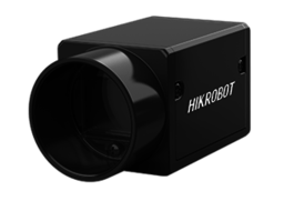
In the two-dimensional image processing and analysis of coarse aggregate, image acquisition is the first step. In this step, the camera equipment Haikang Robot Industrial Camera, the illumination intensity is 1.255 Lm and the input and output equipment will affect the imaging quality, so it is very important to choose appropriate equipment and parameters.
Before performing image processing, we must first collect images. Collecting suitable digital images will enable better image processing. Angle and illumination focal length are factors that must be considered. The camera used in this experiment was a Hikvision Robot in conjunction with the Hikvision Industrial Camera Client software MVS. MVS is a setting management software that was specially launched for the Hikvision Industrial Camera. The official version of Hikvision Industrial Camera Client MVS integrates a series of functions, such as information management, IP configuration, network card configuration, and firmware upgrading, to help users better debug cameras. Camera related parameters are shown in Table 1.
| Camera model | Resolution | Data interface | Sensor type | Pixel size | Photo format | Spectrum |
|---|---|---|---|---|---|---|
| MV-CE050-30GM | GigE | CMOS | BMP | Black and white |
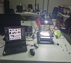
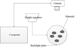
A two-dimensional image acquisition and processing system for coarse aggregate was designed in accordance with two-dimensional image analysis theory. The system consists of three parts: an image acquisition system (digital camera), a storage platform, and a digital image processing system. he schematic diagram of the image analysis system is mainly composed of a computer, a brightness regulator, a camera, a backlight board, and a material, as shown in Figure 1 below. The real view of image acquisition is shown in Figure 2. It can be visualized that the acquired image is displayed in real time.
|
| Figure 1. Schematic diagram of the image analysis system |
| Figure 2. Image acquisition scene |
According to the principle of the imaging method, particles with a diameter larger than 4.75 mm after mechanical screening were uniformly spread on the glass background plate of the image acquisition device, and the brightness of the bottom plate is adjusted by the digital light source controller. Then, an industrial camera with a resolution of was used for shooting, the Halcon version 20.11 code-based particle size detection platform was used to process the collected pictures, and the characteristic parameters of particles larger than 4.75 mm were obtained by the algorithm compiled by the detection platform.
For image acquisition, parameter calibration should be carried out first to establish the link between internal parameters and external parameters, the pixel distance is transformed into the overall coordinate system, and then the actual parameters are obtained.
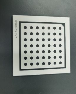
Calibration was performed with the standard calibration plate method and the calibration assistant in HALCON software, Calibration plate size: HC050-2. 5 7*7. The calibration plate is shown in Figure 3.
|
| Figure 3. Calibration board (HC050-2.5 7*7) |
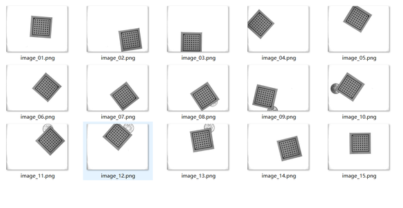
Generally, 12-20 images are collected during shooting so that the calibration plate covers the whole image acquisition area, and then one image is selected as the reference. This time, 15 pictures were taken, and the file image_15 was selected. The calibration plate was located in the center of the image acquisition area as the reference. The image set acquired by the calibration board is shown in Figure 4.
|
| Figure 4. Images collected by the calibration board method |
2.2 Image processing
After image preprocessing, the boundary contour of each coarse aggregate is obtained, and finally, the pixel coordinates of the boundary contour are extracted. The longest axis, shortest axis, angularity, and surface texture of the coarse aggregate are calculated by processing the pixel coordinate data according to the two-dimensional morphology characterization method.
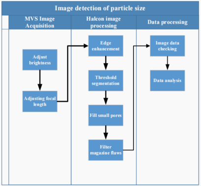
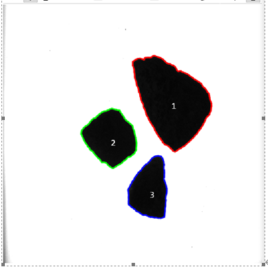
The flow chart of related algorithms used in the detection process is shown in the figure, including basic image processing methods such as image enhancement and threshold segmentation of the initial image. The details are shown in Figure 5. Figure 6 is a collection diagram with particle size greater than 4.75 mm.
|
| Figure 5. Detection flow chart |
|
| Figure 6. Collection diagram of particles with particle size > 4.75 mm |
The following first-order parameters are obtained: area, perimeter, equivalent ellipse perimeter, circumscribed polygon perimeter, equivalent diameter, circumscribed circle radius, and inscribed circle radius.
The following quadratic parameters are obtained: angularity, flatness, roundness and roughness.
3. Selection and calculation of the characterization parameters of the rock crushing effect
3.1 Calculation of characterization parameters of particle breakage degree
The crushing ratio and unit power consumption (energy consumption per unit mass of crushed products) are the basic technical and economic indexes of crushing machinery. The unit power consumption is used to judge whether the power consumption of crushing machinery is economical, and the crushing ratio is used to explain the characteristics of the crushing process and identify the crushing quality. Even if the unit power consumption of the two crushing machines is the same, if the crushing ratio is different, the economic effects of the two machines will be different. Generally, machines with large crushing ratios have higher operating efficiency. Therefore, to identify the operating efficiency of crushing machinery, its unit power consumption and crushing ratio should be considered at the same time.
The crushing ratio refers to the ratio of feed particle size to product particle size in the crusher. This ratio indicates the degree of material crushing, which directly affects the energy consumption and processing capacity of the crusher.
3.1.1 Maximum crushing ratio
Tthe formula is as follows:
|
|
(1) |
where means maximum, indicates the maximum particle diameter of the incoming material (mm), and indicates the maximum particle diameter of the finished product (mm).
Due to different customs, large-particle standardization methods are different. In Britain and America, a material is considered to have a large particle size if 80% of the material can pass through the corresponding sieve hole width. In Russia and China, 95% of the material must pass through the corresponding sieve hole width.
Application object: This calculation method is often used in concentrators and quarries because the width of the crusher inlet should be determined according to the maximum particle size of the feed ore.
3.1.2 Surface crushing ratio: the ratio of the width of the inlet and outlet of the crusher
The definition is
|
|
(2) |
where represents the width of the inlet (mm) and represents the width of the outlet (mm).
The value 0.85 is the width coefficient of the crusher used to hold the materials. The width of the discharge port is S. Coarse crushers are different from medium and fine crushers; the former has a large width, and the latter has a small width.
Application object: Because this method does not necessitate the sieving and analysis of a large amount of material, an approximate calculation can be carried out by knowing the widths of the inlet and outlet of the crusher. This calculation method is simple and rapid, so it is widely used in production.
3.1.3 Average crushing ratio: the ratio of the average particle size of materials before and after crushing
The value is expressed as
|
|
(3) |
where represents the average particle size (mm) of the material before crushing and represents the average particle size (mm) of the stone after crushing.
Application object: Because the ore before and after crushing is different in size and shape, it can be represented by the average particle size. Therefore, the crushing ratio calculated from the average particle size can truly reflect the crushing degree; this parameter is mostly used in theoretical research.
On the basis of the above considerations, the average crushing ratio was selected for later analysis and calculation.
3.2 Sand formation rate
The sand formation rate is the percentage of sand used in concrete relative to the total sand and gravel mass. Generally, a change in the sand formation rate often makes the total surface area of the aggregate change, which affects the dynamic mixing of concrete. Therefore, the conditions producing the best cement slurry are used to calculate the sand formation rate.
When the sand ratio is too large, the total surface area and the corresponding porosity of the aggregate will change accordingly; therefore, more cement will be needed as filler, and the added cement will produce a decrease in fluidity. When the sand ratio is too small, the void ratio of the aggregate will change greatly, and the requirements will be high. Accordingly, the fluidity of the concrete will be poor, so bonding and water retention will decrease, and grouting will easily occur.
3.3 Description of geometric parameters of particle shape
A series of indexes for evaluating the two-dimensional shape parameters of particles have been used in previous research [15-16].
Ye Jiabing et al.[17] selected three representative particle shape evaluation parameters for research. The length-width ratio, flatness, and sphericity can sensitively reflect the degree of deviation from spherical particles and can be preferentially used as particle shape evaluation parameters.
3.4 Angularity
Angularity, as a parameter to characterize the morphology of particles, has been mentioned in many studies. At present, the ratio of the circumference of the minimum circumscribed polygon to the equivalent ellipse of the particle is generally used to define angularity
|
|
(4) |
where represents the perimeter of the minimum circumscribed polygon of the particle, and represents the equivalent ellipse of the particle.
3.5 Roundness (shape index)
Roundness can vividly represent the roundness of particles because of their irregularity (the projected perimeter of a particle must be greater than the equivalent area perimeter). Therefore, the roundness value e is always greater than 1, and the specific calculation formula is as follows
|
|
(5) |
where represents the projected perimeter of the particle itself, and represents the equivalent projected area of the particle.
3.6 Overall profile coefficient
The overall profile coefficient represents the ratio of the circumference of the equivalent area πD to the circumference P of the particle itself. Because rock particles cannot be completely round, this value is generally less than 1, and its value is a maximum only when the particle has a standard round shape. For a given area, the smaller the value of the overall profile coefficient is, the more the overall shape of the particle deviates from circular, and the more irregular and coarse the shape is. Therefore, the overall profile coefficient can describe the morphological characteristics of the particle as a whole
|
|
(6) |
In this paper, the characterization parameters of the rock crushing effect can be subdivided into two parts. The first part describes the difficulty of particle crushing, and the other part describes the particle shape after crushing. The crushing difficulty is characterized by the true crushing ratio and sand formation rate, while the particle shape is characterized by edges and corners, roundness, and overall profile coefficient.
4. Experimental study on key parameters affecting the crushing effect
Once the most relevant characterization parameters for evaluating the rock fragmentation process are established by our chosen image processing method, the influence of rock fragmentation particles on loading mode and feeding particle size can be analyzed.
4.1 Experimental study on the influence of loading mode on the rock crushing effect
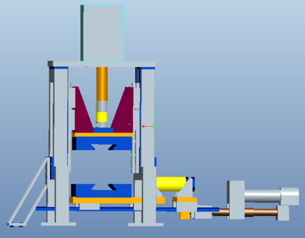
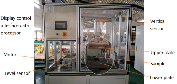
Shear extrusion has different effects on material crushing because of its different mechanisms. Existing artificial sand and gravel production equipment is mainly based on mechanical crushing, and the force application methods of crushing machines include crushing, splitting, breaking, grinding, stripping, and impact. Most of the crushing machines used in industrial production include a variety of force application methods. At present, there is a lack of comparative analysis between pairs of single loading modes. The equipment model selected in this test is FZDH-01, and the shear extrusion equipment is compared and analyzed. The experimental model diagram and physical diagram are shown in Figures 7 and 8, respectively.
|
| Figure 7. Experimental model diagram |
|
| Figure 8. Physical diagram of the experimental crusher |
The crusher squeezes the material in the vertical direction for crushing. Shear force is used to break the material horizontally.
In this experiment, feed particles with a particle size of 9.5mm-16 mm were selected for use in the crusher, and crushing by shearing and extrusion was compared and analyzed.
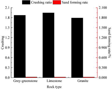
According to the analysis of the sand formation rate and crushing ratio under shear conditions, the crushing ratios of the three rocks studied follow the order limestone (1.873), limestone (1.846), and granite (1.791) from high to low. The sand formation rate from high to low is limestone (2.016%), granite (1.911%) and limestone (1.881%). Through Figure 9, it can be clearly seen that gray‒greenstone is more suitable for research and analysis.
|
| Figure 9. Sand formation rate and crushing ratio under shear conditions |
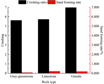
According to the analysis of sand forming ratio and crushing ratio under extrusion, the crushing ratio of limestone, limestone and granite increases, which are 5.61, 5.72 and 6.97 respectively. The sand-forming rate of limestone, limestone and granite decreased by 6.97%, 19.84% and 17.91%, respectively, as shown in Figure 10.
|
| Figure 10. Sand formation rate and crushing ratio under extrusion |
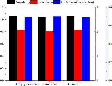
Through the analysis of crushed rocks of different materials under extrusion, it can be seen that the influencing factors are angularity, roundness, and overall profile coefficient. As can be seen from the above Figure 11. It can be seen from the above figure that granite has the smallest angularity, limestone has the smallest roundness and granite has the smallest overall profile coefficient.
|
| Figure 11. Trends of grain shape characterization parameters of rocks composed of different materials after crushing under extrusion |
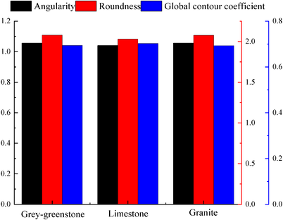
According to the analysis of the characterization parameters of different materials of broken rocks under shear condition, it can be seen that the angularity and roundness at this time are close to those in limestone and granite. As shown in Figure 12, the angularity at this time is 1.0404 and 1.0405 respectively. The roundness is 1.0561 and 1.0559 respectively. In the overall contour coefficient, the maximum of limestone is 0.7021.
|
| Figure 12. Trend of grain shape characterization parameters of rocks composed of different materials after crushing under shear conditions |
4.2 Experimental study on the influence of feed particle size on granite crushing effect
4.2.1 Effect of feed particle size on crushing degree
The feed particle size will affect the sand formation efficiency in vertical shaft impact crushing. Because the material particles are heterogeneous solids filled with cracks, the random distribution of cracks determines the variation in local strength in rocks. Generally, the larger the particle size of rock is, the more cracks it has. The crushing effect parameters are shown in Table 2.
| Test factor | Crushing effect parameters | ||||||
|---|---|---|---|---|---|---|---|
| Material type | Crushing mode | Particle size (mm) | Crushing ratio | Sand formation rate | Angularity | Roundness | Overall profile coefficient |
| Gray‒greenstone | Extrusion | 4.75-9.5 | 6.0093 | 0.2033 | 1.042287 | 2.11903 | 0.69013 |
| 9.5-16 | 6.5830 | 0.2368 | 1.041036 | 2.27573 | 0.66985 | ||
| 16-19 | 5.1461 | 0.0849 | 1.057625 | 2.26593 | 0.66797 | ||
| Shear | 4.75-9.5 | 1.9259 | 0.0609 | 1.064623 | 2.08788 | 0.69284 | |
| 9.5-16 | 1.8777 | 0.0442 | 1.049565 | 2.06742 | 0.69284 | ||
| 16-19 | 2.4444 | 0.0307 | 1.032105 | 2.02849 | 0.70589 | ||
| Limestone | Extrusion | 4.75-9.5 | 1.9133 | 0.0468 | 1.029862 | 1.89925 | 0.72930 |
| 9.5-16 | 6.0702 | 0.2258 | 1.042174 | 2.21980 | 0.67699 | ||
| 16-19 | 5.0435 | 0.0939 | 1.047699 | 2.31480 | 0.66129 | ||
| Shear | 4.75-9.5 | 2.0675 | 0.0153 | 1.054777 | 2.25641 | 0.67045 | |
| 9.5-16 | 1.9273 | 0.0300 | 1.03562 | 2.05476 | 0.70046 | ||
| 16-19 | 1.7962 | 0.0100 | 1.003074 | 1.77350 | 0.75094 | ||
| Granite | Extrusion | 4.75-9.5 | 5.2460 | 0.1309 | 1.04766 | 2.40880 | 0.65506 |
| 9.5-16 | 6.8890 | 0.2230 | 1.041795 | 2.35674 | 0.65915 | ||
| 16-19 | 7.1164 | 0.1162 | 1.040363 | 2.39666 | 0.65164 | ||
| Shear | 4.75-9.5 | 1.9732 | 0.0056 | 1.07024 | 2.13329 | 0.68467 | |
| 9.5-16 | 1.7462 | 0.0213 | 1.052678 | 2.06073 | 0.69787 | ||
| 16-19 | 1.8037 | 0.0471 | 1.052355 | 2.05109 | 0.69989 | ||
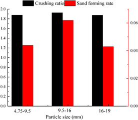
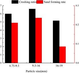
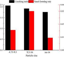
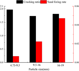
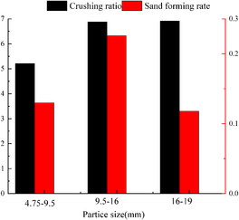
From Table 2, we can see that the crushing ratios of limestone and granite with different particle sizes are relatively high under extrusion. The sand formation rates of limestone under shear loading are 0.0609, 0.0442, and 0.0307. Gray‒greenstone, limestone, and granite have little change in angularity. The overall profile coefficients of the three rocks range from 0.65000 to 0.75100 under different feed particle sizes.
Figure 13 to 18 show the effect of feed particle size on breakage under shear and extrusion, respectively.
|
| Figure 13. Gray‒greenstone shear |
|
| Figure 14. Gray‒greenstone extrusion |
|
| Figure 15. Limestone shear |
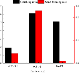
|
| Figure 16. Limestone extrusion |
|
| Figure 17. Granite shear |
|
| Figure 18. Granite extrusion |
4.2.2 Influence of feed particle size on morphological characteristics of crushed rock
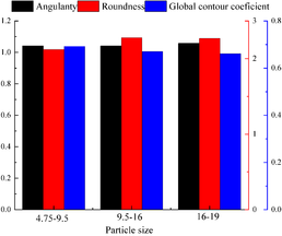
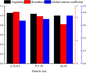
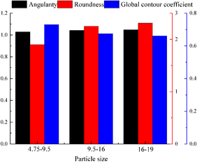
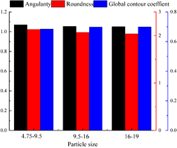
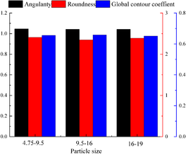
Figures 19, 21 and 23 show that under shear load, the angularity and roundness of gray‒green rock with a feed particle size between 9.5mm and 16mm are relatively good, with values of 1.0641 and 2.0860, respectively. The overall profile coefficient of limestone with a feed particle size between 16mm and 19mm is 0.752. The angularity and roundness of granite decrease at a feed particle size of 9.5mm to 16mm, but the overall profile coefficient increases to 0.7005.
Through Figures 20, 22 and 24, the analysis of the previous figures, under extrusion, the parameters of gray‒green rock after crushing change obviously starting at a particle size of 9.5mm-16mm; the angularity rises, and the roundness and overall profile coefficient decrease. When the particle size of limestone is 9.5mm-16mm, the trend is opposite to that of limestone, and the angularity increases, while the roundness and overall profile coefficient decrease. The overall profile coefficient of granite decreases from 0.6582 to 0.6516 at a grain size of 9.5mm-16mm, and the angularity decreases from 1.0420 to 1.0398. However, the corresponding roundness rises sharply from 2.15 to 2.39.Due to the limitation of experimental conditions, the current research hopes to comprehensively utilize machine vision and advanced processing software to help the development of particle breakage.
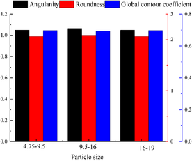
|
| Figure 19. Gray‒green rock shear |
|
| Figure 20. Gray‒greenstone extrusion |
|
| Figure 21. Limestone shear |
|
| Figure 22. Limestone extrusion |
|
| Figure 23. Granite shear |
|
| Figure 24. Granite extrusion |
5. Conclusions
An imaging approach was used to detect the crushing effect of rock particles. The influence of loading mode and feeding particle size on the degree of rock crushing and the influence of rock morphology after crushing are analyzed and the corresponding experimental study is carried out, the main conclusions are as follows:
(1) Under a shear load, the crushing ratio decreases from 1.881 to 1.772. Under extrusion, the crushing ratio increases from 5.55 to 6.96.
(2) Under extrusion, the angularity shows an upward trend, with the highest value of 1.04301. Roundness first decreases and then increases with an inflection point of 2.23. The overall profile coefficient first increases and then decreases, and the inflection point is 0.675. Under shear loading, angularity first decreases and then rises with an inflection point of 1.0404. Roundness also decreases first and then increases with an inflection point of 2.03. In contrast, the overall profile coefficient rises first and then falls, showing an approximately symmetrical inflection point of 0.7028.
(3) Under a shear load, when the inlet particle size is between 9.5mm and 16mm, rocks composed of different materials have obvious differences. Under these conditions, the crushing ratio of limestone is 1.915, and the sand formation rate is 2.89%. Under extrusion, when the inlet particle size is between 9.5mm and 16mm, there are obvious variations between rocks composed of different materials; in particular, when the inlet particle size of granite is between 16mm and 19mm, the crushing ratio is 7.21, and the sand formation rate is 11%.
(4) The analysis of the morphological characteristics of the broken rock shows that the parameters of granite with a grain size between 9.5mm and 16mm tend to increase: the angularity is 1.055, the roundness is 2.06, and the overall profile coefficient is 0.7001. Under extrusion, rock composed of different materials changes from 9.6mm to 16mm. The angularity, roundness and overall profile coefficient, which have a great influence on the morphological characteristics of broken rock, are 1.046, 2.33 and 1.9, respectively.
It shows that the image-based detection system for detecting the effect of rock particle breakage has high applicability and credibility, and has the advantages of real-time and stability, which can provide a basis for the follow-up research on intelligent mine construction and equipment optimization, and is worthy of further popularization and application.
Declaration of Competing Interest
The authors certify that they have no affiliations with or involvement in any organization or entity with any financial interest (such as honoraria; educational grants; participation in speakers' bureaus; membership, employment, consultancies, stock ownership, or other equity interest; and expert testimony or patent-licensing arrangements) or nonfinancial interest (such as personal or professional relationships, affiliations, knowledge or beliefs) in the subject matter or materials discussed in this manuscript.
Data Availability The data will be provided upon request and can be used without any conflict of interest.
Acknowledgments
This project is funded by Fujian University of Technology for the Fujian University of Technology Science and Technology Project, Project No. GY-Z220201. Agricultural University Industry-University Cooperation Project, Project No. 2020N5015. Key Research and Industrialization Project of Technological Innovation in Fujian Province (University-Enterprise Joint Category), Project No. 2023XQ002.
References
[1] Hamzeloo E., Massinaei M., Mehrshad N. Estimation of particle size distribution on an industrial conveyor belt using image analysis and neural networks. Powder technology, 261:185-190, 2014. https://doi.org/10.1016/j.powtec.2014.04.038
[2] Chen A.L., Chen B.Z., Feng C.A. Image analysis algorithm and verification for on-line molecular sieve size and shape inspection. Advanced Powder Technology, 25(2):508-513, 2014. https://doi.org/10.1016/j.apt.2013.08.004
[3] Jug J., Strelec S., Gazdek M., Kavur B. Fragment size distribution of blasted rock mass. IOP Conference Series: Earth and Environmental Science. IOP Publishing, 95(4):042013, 2017.
[4] Yang J., Chen S. An online detection system for aggregate sizes and shapes based on digital image processing. Mineralogy and Petrology, 111(1):135-144, 2017. https://doi.org/10.1007/s00710-016-0458-y
[5] Zheng J., Hryciw R.D. Soil particle size and shape distributions by stereophotography and image analysis. Geotech. Test. J, 40(2):317-328, 2017.
[6] Shehu S.A., Yusuf K.O., Hashim M.H.M. Comparative study of WipFrag image analysis and Kuz-Ram empirical model in granite aggregate quarry and their application for blast fragmentation rating. Geomechanics and Geoengineering, 17(1):197-205, 2022.
[7] Huang-Yi W., Luo-Jian Y .Study on the crushing mechanism and parameters of the two-flow crusher. Applied Mathematics and Nonlinear Sciences, 7(2):875-890, 2022. https://doi.org/10.2478/amns.2021.2.00172
[8] Chen H., Tang L., Chen J., Xu X.-R. Study on measurement technique of sediment particle size base on RGB image. Journal of Sediment Research, 01:25-29, 2015.
[9] Yang Y., Wei Z., Chen Y., Ren B. Study on the shapes of tailings particles based on microscopy and image processing technologies. Chin. J. Rock Mechan. Engin, S1:3689-3695, 2017.
[10] Li Z., Ye Y., Tong X., Li K. Study on the mechanism of particle breakage under new composite loads. Journal of Engineering and Technological Sciences, 51(2):231-250, 2019.
[11] Chen J., Zhang Z., Xu W., Li L. Quantitative method of shape parameters of mineral particles based on image processing. Journal of Engineering Geology, 29(1):59-68, 2021.
[12] Zhang L., Chu M., Deng X., Chen Z. Graph-based detection technology for mineral grains image. Journal of Hefei University of Technology (Natural Science), 44(09):1193-1197+1209, 2021.
[13] Wu M., Wang J. Constitutive modeling of natural sands using a deep learning approach accounting for particle shape effects. Powder Technology, 404:117439, 2022.
[14] Höving S., Neuendorf L., Betting T., Kockmann N. Determination of particle size distributions of bulk samples using micro-computed tomography and artificial intelligence. Materials, 16(3):1002, 2023.
[15] Lin Y., Wu M., Wang P. Field test and analysis of multiple vibration-damped track structures for 120 km/h subway. Railway Standard Design, 62(02):67-71, 2018.
[16] Guan Z., He Y., Gao X., Den T. 2D shape characteristic and the clump reconstruction of gravel particle in granite residual soil. Journal of Water Resources and Architectural Engineering, (04):4-10, 2021.
[17] Ye J., Zhang J., Zou W. Influences of grain shape on pore characteristics of filled breakstone aggregate. Rock and Soil Mechanics, 39(12):4457-4467, 2018.Document information
Published on 14/11/23
Accepted on 23/10/23
Submitted on 25/05/23
Volume 39, Issue 4, 2023
DOI: 10.23967/j.rimni.2023.10.007
Licence: CC BY-NC-SA license
Share this document
Keywords
claim authorship
Are you one of the authors of this document?
