(→4.2. Example 2) |
Zhangxuegang (talk | contribs) (Add a department to the Acknowledgments section.) (Tag: Visual edit) |
||
| (16 intermediate revisions by one other user not shown) | |||
| Line 52: | Line 52: | ||
==2. Geometry of curvilinear cylindrical gears== | ==2. Geometry of curvilinear cylindrical gears== | ||
| − | ===2.1 | + | ===2.1 Generating principle of curvilinear cylindrical gears by face-milling cutters=== |
In order to generate the gear tooth surfaces, the first task is the establishment of the virtual face-milling cutter surfaces. A brief generating mechanism of the gear tooth surfaces is shown in [[#img-1|Figure 1]]. The outer and inner blades of the face-milling cutter are employed for the generation of concave and convex sides of the gear tooth surfaces, respectively. Generating process of the cutter blade surfaces is as follows: | In order to generate the gear tooth surfaces, the first task is the establishment of the virtual face-milling cutter surfaces. A brief generating mechanism of the gear tooth surfaces is shown in [[#img-1|Figure 1]]. The outer and inner blades of the face-milling cutter are employed for the generation of concave and convex sides of the gear tooth surfaces, respectively. Generating process of the cutter blade surfaces is as follows: | ||
| Line 124: | Line 124: | ||
After one tooth space is generated by the face-milling cutter, the gear blank is indexed by one tooth pitch angle, and the generating mechanism of the gear continues to generate the next tooth space, until all tooth spaces have been formed. | After one tooth space is generated by the face-milling cutter, the gear blank is indexed by one tooth pitch angle, and the generating mechanism of the gear continues to generate the next tooth space, until all tooth spaces have been formed. | ||
| − | ===2.2 | + | ===2.2 Derivation of mathematical model of the wheel tooth surfaces=== |
[[#img-1|Figure 1]] (Right) shows the straight-line profiles of the face-milling cutter for the generation of the wheel tooth surfaces. The inner and outer blade profiles are divided into two parts: the straight-line profile, which will be used for generation of the working part of the wheel tooth surfaces, and the circular arc profile, which will be used for generation of the fillet part of the wheel tooth surfaces. The variable <math display="inline"> u_g </math> represents the distance between arbitrary points on the straight-line profile and the origin of coordinate system <math display="inline">S_{ib}</math> or <math display="inline">S_{ob}</math>, and the variable <math display="inline">\lambda_g </math> represents the polar angle of arbitrary points on the circular arc profile. | [[#img-1|Figure 1]] (Right) shows the straight-line profiles of the face-milling cutter for the generation of the wheel tooth surfaces. The inner and outer blade profiles are divided into two parts: the straight-line profile, which will be used for generation of the working part of the wheel tooth surfaces, and the circular arc profile, which will be used for generation of the fillet part of the wheel tooth surfaces. The variable <math display="inline"> u_g </math> represents the distance between arbitrary points on the straight-line profile and the origin of coordinate system <math display="inline">S_{ib}</math> or <math display="inline">S_{ob}</math>, and the variable <math display="inline">\lambda_g </math> represents the polar angle of arbitrary points on the circular arc profile. | ||
| Line 222: | Line 222: | ||
|- | |- | ||
| <span id='eq9'></span><math>\boldsymbol{r}_c^{\left(G\right)}({\theta}_g,u_g)=\boldsymbol{M}_{c,b}({\theta }_g)\boldsymbol{r}_b^{\left(G\right)}(u_g)=\left[\begin{array}{c} | | <span id='eq9'></span><math>\boldsymbol{r}_c^{\left(G\right)}({\theta}_g,u_g)=\boldsymbol{M}_{c,b}({\theta }_g)\boldsymbol{r}_b^{\left(G\right)}(u_g)=\left[\begin{array}{c} | ||
| − | (\pm u_g \sin{\alpha }_n-R\, \pm \, \frac{\pi m}{4})\cos{\theta }_g\\ | + | \left(\pm u_g \sin{\alpha }_n-R\, \pm \, \frac{\pi m}{4}\right)\cos{\theta }_g\\ |
u_g \cos{\alpha }_n\\ | u_g \cos{\alpha }_n\\ | ||
| − | (\pm u_g \sin{\alpha }_n-\, R \pm \frac{\pi m}{4})\sin{\theta }_g\\ | + | \left(\pm u_g \sin{\alpha }_n-\, R \pm \frac{\pi m}{4}\right)\sin{\theta }_g\\ |
1 | 1 | ||
\end{array}\right]</math> | \end{array}\right]</math> | ||
| Line 410: | Line 410: | ||
{| style="text-align: center; margin:auto;" | {| style="text-align: center; margin:auto;" | ||
|- | |- | ||
| − | | <span id='eq19'></span> <math>f(u_g,{\theta }_g,{\psi }_g)=(\frac{\partial \boldsymbol{r}_1^{\left(G\right)}}{\partial {\theta }_g}\times \frac{\partial \boldsymbol{r}_1^{\left(G\right)}}{\partial u_g})\cdot \frac{\partial \boldsymbol{r}_1^{\left(G\right)}}{\partial {\psi }_g} = 0</math> | + | | <span id='eq19'></span> <math>f(u_g,{\theta }_g,{\psi }_g)=\left(\frac{\partial \boldsymbol{r}_1^{\left(G\right)}}{\partial {\theta }_g}\times \frac{\partial \boldsymbol{r}_1^{\left(G\right)}}{\partial u_g}\right)\cdot \frac{\partial \boldsymbol{r}_1^{\left(G\right)}}{\partial {\psi }_g} = 0</math> |
|} | |} | ||
| style="width: 5px;text-align: right;white-space: nowrap;" | (19) | | style="width: 5px;text-align: right;white-space: nowrap;" | (19) | ||
| Line 457: | Line 457: | ||
In Eq. (21), <math display="inline">u_g</math> and <math display="inline">\theta_g</math> are the parameters of the working tooth surfaces. In Eq. (22), <math display="inline">\lambda_g</math> and <math display="inline">\theta_g</math> are the parameters of the fillet surfaces, and <math display="inline">\psi_g</math> is the generalized parameter of movement. Arbitrary point coordinates on the wheel tooth surfaces will be solved by numerical method. | In Eq. (21), <math display="inline">u_g</math> and <math display="inline">\theta_g</math> are the parameters of the working tooth surfaces. In Eq. (22), <math display="inline">\lambda_g</math> and <math display="inline">\theta_g</math> are the parameters of the fillet surfaces, and <math display="inline">\psi_g</math> is the generalized parameter of movement. Arbitrary point coordinates on the wheel tooth surfaces will be solved by numerical method. | ||
| − | ===2.3 | + | ===2.3 Derivation of mathematical model of pinion tooth surfaces=== |
The generation of a mathematical model of the pinion tooth surfaces is similar to that of the wheel tooth surfaces. They distinguish only in different cutter blade profiles. Here, the face-milling cutter with the parabolic blade profiles is used to generate the pinion tooth surfaces. [[#img-2|Figure 2]] shows the parabolic profiles of the face-milling cutter. The parabolic profiles of the cutter retain tangent to the standard blade with straight-line profiles. The point of tangency is located at arbitrary positions on the straight-line profiles. The distance between the point of tangency and the cutter pitch plane is <math display="inline">\Delta y_{tp}</math> along the vertical direction. The distance between the center points of circular arc profiles and the origin of the coordinate system <math display="inline">S_b</math> is <math display="inline">x_{fc}</math> along the horizontal direction. The variable <math display="inline"> u_p </math> represents the distance between arbitrary points on the parabolic profile and the origin of the coordinate system <math display="inline">S_{ib}</math> or <math display="inline">S_{ob}</math>. The variable <math display="inline">\lambda_p</math> represents the polar angle of arbitrary points on the circular arc profiles. | The generation of a mathematical model of the pinion tooth surfaces is similar to that of the wheel tooth surfaces. They distinguish only in different cutter blade profiles. Here, the face-milling cutter with the parabolic blade profiles is used to generate the pinion tooth surfaces. [[#img-2|Figure 2]] shows the parabolic profiles of the face-milling cutter. The parabolic profiles of the cutter retain tangent to the standard blade with straight-line profiles. The point of tangency is located at arbitrary positions on the straight-line profiles. The distance between the point of tangency and the cutter pitch plane is <math display="inline">\Delta y_{tp}</math> along the vertical direction. The distance between the center points of circular arc profiles and the origin of the coordinate system <math display="inline">S_b</math> is <math display="inline">x_{fc}</math> along the horizontal direction. The variable <math display="inline"> u_p </math> represents the distance between arbitrary points on the parabolic profile and the origin of the coordinate system <math display="inline">S_{ib}</math> or <math display="inline">S_{ob}</math>. The variable <math display="inline">\lambda_p</math> represents the polar angle of arbitrary points on the circular arc profiles. | ||
| Line 958: | Line 958: | ||
|- | |- | ||
| <span id='eq52'></span> <math>\boldsymbol{M}_{l,m}=\left[\begin{array}{cccc} | | <span id='eq52'></span> <math>\boldsymbol{M}_{l,m}=\left[\begin{array}{cccc} | ||
| − | cos(\Delta H) & 0 & sin(\Delta H) & 0\\ | + | \cos (\Delta H) & 0 & \sin (\Delta H) & 0\\ |
0 & 1 & 0 & 0\\ | 0 & 1 & 0 & 0\\ | ||
| − | -sin(\Delta H) & 0 & cos(\Delta H) & 0\\ | + | -\sin (\Delta H) & 0 & \cos (\Delta H) & 0\\ |
0 & 0 & 0 & 1 | 0 & 0 & 0 & 1 | ||
\end{array}\right]</math> | \end{array}\right]</math> | ||
| Line 1,083: | Line 1,083: | ||
{| class="wikitable" style="margin: 1em auto 0.1em auto;border-collapse: collapse;font-size:85%;width:auto;" | {| class="wikitable" style="margin: 1em auto 0.1em auto;border-collapse: collapse;font-size:85%;width:auto;" | ||
|-style="text-align:center" | |-style="text-align:center" | ||
| − | ! Type of assembly errors | + | ! style="text-align:left;" | Type of assembly errors |
| + | | colspan='4' style="text-align: center;"|<math display="inline">\Delta V</math> (°) | ||
| + | | colspan='5' style="text-align: center;"|<math display="inline">\Delta H</math> (°) | ||
| + | | colspan='5' style="text-align: center;"|<math display="inline">\Delta A</math> (mm) | ||
| + | | colspan='6' style="text-align: center;"|<math display="inline">\Delta C</math> (mm) | ||
|- | |- | ||
| − | + | ! style="text-align:left;" | Error values | |
| style="text-align: center;"|0 | | style="text-align: center;"|0 | ||
| style="text-align: center;"|0.05 | | style="text-align: center;"|0.05 | ||
| Line 1,153: | Line 1,157: | ||
<div class="center" style="font-size: 75%;">'''Table 3'''. Design data of different parabola coefficients</div> | <div class="center" style="font-size: 75%;">'''Table 3'''. Design data of different parabola coefficients</div> | ||
| − | <div id='tab- | + | <div id='tab-3'></div> |
{| class="wikitable" style="margin: 1em auto 0.1em auto;border-collapse: collapse;font-size:85%;width:auto;" | {| class="wikitable" style="margin: 1em auto 0.1em auto;border-collapse: collapse;font-size:85%;width:auto;" | ||
|-style="text-align:center" | |-style="text-align:center" | ||
| Line 1,175: | Line 1,179: | ||
{| class="wikitable" style="margin: 0em auto 0.1em auto;border-collapse: collapse;width:auto;" | {| class="wikitable" style="margin: 0em auto 0.1em auto;border-collapse: collapse;width:auto;" | ||
|-style="background:white;" | |-style="background:white;" | ||
| − | |style="text-align: center;padding:10px;"| [[Image:Draft_Xuegang_614753900-image66.jpeg| | + | |style="text-align: center;padding:10px;"| [[Image:Draft_Xuegang_614753900-image66.jpeg|350px]] |
|- | |- | ||
| style="background:#efefef;text-align:left;padding:10px;font-size: 85%;"| '''Figure 8'''. Evolution of contact stresses for gear drives designed for example 2 | | style="background:#efefef;text-align:left;padding:10px;font-size: 85%;"| '''Figure 8'''. Evolution of contact stresses for gear drives designed for example 2 | ||
| Line 1,184: | Line 1,188: | ||
{| class="wikitable" style="margin: 0em auto 0.1em auto;border-collapse: collapse;width:auto;" | {| class="wikitable" style="margin: 0em auto 0.1em auto;border-collapse: collapse;width:auto;" | ||
|-style="background:white;" | |-style="background:white;" | ||
| − | |style="text-align: center;padding:10px;"| [[Image:Draft_Xuegang_614753900-image67.png| | + | |style="text-align: center;padding:10px;"| [[Image:Draft_Xuegang_614753900-image67.png|650px]] |
|- | |- | ||
| style="background:#efefef;text-align:left;padding:10px;font-size: 85%;"| '''Figure 9'''. Stress contours at contact position 10 for example 2 | | style="background:#efefef;text-align:left;padding:10px;font-size: 85%;"| '''Figure 9'''. Stress contours at contact position 10 for example 2 | ||
| Line 1,195: | Line 1,199: | ||
{| class="wikitable" style="margin: 0em auto 0.1em auto;border-collapse: collapse;width:auto;" | {| class="wikitable" style="margin: 0em auto 0.1em auto;border-collapse: collapse;width:auto;" | ||
|-style="background:white;" | |-style="background:white;" | ||
| − | |style="text-align: center;padding:10px;"| [[Image:Draft_Xuegang_614753900-image68.jpeg| | + | |style="text-align: center;padding:10px;"| [[Image:Draft_Xuegang_614753900-image68.jpeg|350px]] |
|- | |- | ||
| style="background:#efefef;text-align:left;padding:10px;font-size: 85%;"| '''Figure 10'''. Evolution of bending stresses for gear drives designed for example 2 | | style="background:#efefef;text-align:left;padding:10px;font-size: 85%;"| '''Figure 10'''. Evolution of bending stresses for gear drives designed for example 2 | ||
| Line 1,202: | Line 1,206: | ||
===4.3. Example 3=== | ===4.3. Example 3=== | ||
| − | + | In this group example, the cutter mean pitch radius is determined as the independent experiment variable. The axial displacement error <math display="inline">\Delta A = 0.2</math> mm, the parabola coefficient <math display="inline">a_{pf}= 0.0015</math> 1/mm, and the offset distance of parabolic profile <math display="inline">\Delta y_{tp} = 0</math> mm. The design data of the cutter mean pitch radius are shown in [[#tab-4|Table 4]]. | |
| − | < | + | <div class="center" style="font-size: 75%;">'''Table 4'''. Design data of the cutter mean pitch radius</div> |
| − | {| style=" | + | <div id='tab-4'></div> |
| + | {| class="wikitable" style="margin: 1em auto 0.1em auto;border-collapse: collapse;font-size:85%;width:auto;" | ||
| + | |-style="text-align:center" | ||
| + | ! style="text-align: left;"| Case | ||
| + | | style="text-align: center;"|1 | ||
| + | | style="text-align: center;"|2 | ||
| + | | style="text-align: center;"|3 | ||
| + | | style="text-align: center;"|4 | ||
|- | |- | ||
| − | + | ! style="text-align: center;vertical-align: top;"| Mean radius of cutter, <math display="inline">R </math> (mm) | |
| − | + | | style="text-align: center;"|40 | |
| − | + | | style="text-align: center;"|60 | |
| − | + | | style="text-align: center;"|80 | |
| − | + | | style="text-align: center;"|100 | |
| − | + | ||
| − | + | ||
| − | | style=" | + | |
| − | | style=" | + | |
| − | | style=" | + | |
| − | | style=" | + | |
|} | |} | ||
| − | + | [[#img-11|Figure 11]] shows the evolution of contact stresses for the gear drives designed for example 3. In the meshing cycle, the maximum contact stresses at any contact position are reduced with the increment of the cutter mean pitch radius. It can be seen from [[#img-12|Figure 12]] that as the cutter radius increases, the width of the contact pattern also increases, at the same time, the increase in the width of the contact pattern leads to a decrease in the contact stress. However, the center point of the contact pattern is more seriously offset under the same assembly error. | |
| − | <div class=" | + | <div id='img-11'></div> |
| − | + | {| class="wikitable" style="margin: 0em auto 0.1em auto;border-collapse: collapse;width:auto;" | |
| + | |-style="background:white;" | ||
| + | |style="text-align: center;padding:10px;"| [[Image:Draft_Xuegang_614753900-image69.jpeg|350px]] | ||
| + | |- | ||
| + | | style="background:#efefef;text-align:left;padding:10px;font-size: 85%;"| '''Figure 11'''. Evolution of contact stresses for gear drives designed for example 3 | ||
| + | |} | ||
| − | |||
| − | |||
| − | |||
| − | <div class=" | + | <div id='img-12'></div> |
| − | ''' | + | {| class="wikitable" style="margin: 0em auto 0.1em auto;border-collapse: collapse;width:auto;" |
| + | |-style="background:white;" | ||
| + | |style="text-align: center;padding:10px;"| [[File:Draft_Xuegang_614753900-image70.png|centre|600x600px]] | ||
| + | |- | ||
| + | | style="background:#efefef;text-align:left;padding:10px;font-size: 85%;"| '''Figure 12'''. Stress contours at contact position 10 for example 3 | ||
| + | |} | ||
| − | |||
| − | + | [[#img-13|Figure 13]] shows the evolution of bending stresses for the gear drives designed for example 3. In the meshing cycle, maximum bending stresses are less affected by the cutter mean pitch radius. To sum up the above, the results show that a higher cutter mean pitch radius can improve the meshing characteristics of the gear drives. | |
| − | + | ||
| − | <div id= | + | <div id='img-13'></div> |
| − | ''' | + | {| class="wikitable" style="margin: 0em auto 0.1em auto;border-collapse: collapse;width:auto;" |
| + | |-style="background:white;" | ||
| + | |style="text-align: center;padding:10px;"| [[Image:Draft_Xuegang_614753900-image71.jpeg|350px]] | ||
| + | |- | ||
| + | | style="background:#efefef;text-align:left;padding:10px;font-size: 85%;"| '''Figure 13'''. Evolution of bending stresses for gear drives designed for example 3 | ||
| + | |} | ||
===4.4. Example 4=== | ===4.4. Example 4=== | ||
| − | In this group example, the offset distance of the parabolic profiles is determined as the independent experiment variable under ideal assembly conditions. The cutter mean pitch radius | + | In this group example, the offset distance of the parabolic profiles is determined as the independent experiment variable under ideal assembly conditions. The cutter mean pitch radius <math display="inline">R = 40</math> mm, and the parabola coefficient <math display="inline">a_{pf}= 0.0005</math>/mm. The design data of the offset distance of the parabolic profiles are shown in [[#tab-5|Table 5]]. |
| − | < | + | <div class="center" style="font-size: 75%;">'''Table 5'''. Design data of the offset distance of parabolic profiles</div> |
| − | {| style=" | + | <div id='tab-5'></div> |
| − | |- | + | {| class="wikitable" style="margin: 1em auto 0.1em auto;border-collapse: collapse;font-size:85%;width:auto;" |
| − | + | |-style="text-align:center" | |
| − | | style=" | + | ! style="text-align: left;"| Case |
| − | | style=" | + | | style="text-align: center;"|1 |
| − | | style=" | + | | style="text-align: center;"|2 |
| − | | style=" | + | | style="text-align: center;"|3 |
| − | | | + | | style="text-align: center;"|4 |
| + | | style="text-align: center;"| 5 | ||
|- | |- | ||
| − | + | ! style="text-align: center;vertical-align: top;"| Offset distance of parabolic profile, <math display="inline">\Delta y_{tp} </math> (mm) | |
| − | | style=" | + | | style="text-align: center;"|0 |
| − | | style=" | + | | style="text-align: center;"|-1 |
| − | | style=" | + | | style="text-align: center;"|-2 |
| − | | style=" | + | | style="text-align: center;"|-3 |
| − | | style=" | + | | style="text-align: center;"|-4 |
|} | |} | ||
| − | + | [[#img-14|Figure 14]] shows the evolution of contact stresses for the gear drives for example 4. In the meshing cycle, the maximum contact stress occurs at contact position 10 and 20, it reduces with higher the offset distance towards tooth root at these contact position. The contact stresses increase with higher the offset distance except contact position 10 and 20. It can be seen from [[#img-15|Figure 15]] that the reason for the reduction of the contact stress at the contact position 10 is that the addendum edge contact is gradually eliminated in the process of increasing the offset amount. Therefore, an appropriate offset amount can reduce the maximum contact stress during the meshing cycle. | |
| − | <div class=" | + | <div id='img-14'></div> |
| − | + | {| class="wikitable" style="margin: 0em auto 0.1em auto;border-collapse: collapse;width:auto;" | |
| + | |-style="background:white;" | ||
| + | |style="text-align: center;padding:10px;"| [[Image:Draft_Xuegang_614753900-image72.jpeg|350px]] | ||
| + | |- | ||
| + | | style="background:#efefef;text-align:left;padding:10px;font-size: 85%;"| '''Figure 14'''. Evolution of contact stresses for gear drives designed for example 4 | ||
| + | |} | ||
| − | |||
| − | |||
| − | <div class=" | + | <div id='img-15'></div> |
| − | + | {| class="wikitable" style="margin: 0em auto 0.1em auto;border-collapse: collapse;width:auto;" | |
| + | |-style="background:white;" | ||
| + | |style="text-align: center;padding:10px;"| [[Image:Draft_Xuegang_614753900-image73.png|600px]] | ||
| + | |- | ||
| + | | style="background:#efefef;text-align:left;padding:10px;font-size: 85%;"| '''Figure 15'''. Stress contours at contact position 10 for example 4 | ||
| + | |} | ||
| − | |||
| − | |||
| − | + | [[#img-16|Figure 16]] shows the evolution of bending stresses for the gear drives designed for example 4. In the meshing cycle, maximum bending stresses are reduced with the increment of the offset distance of the parabolic profile. Bending stresses are increased with the increment of the offset distance during the first half cycle (Contact position 1-11). In addition, bending stresses are reduced with the increment of the offset distance during the second half cycle (Contact position 11-21). To sum up the above, the obtained results show higher offset distance toward the tooth root will bring about worse mechanical behavior, higher vibration, and noise for the gear drives without edge contact. | |
| − | <div id= | + | <div id='img-16'></div> |
| − | + | {| class="wikitable" style="margin: 0em auto 0.1em auto;border-collapse: collapse;width:auto;" | |
| − | + | |-style="background:white;" | |
| − | + | |style="text-align: center;padding:10px;"| [[Image:Draft_Xuegang_614753900-image74.jpeg|350px]] | |
| − | ''' | + | |- |
| + | | style="background:#efefef;text-align:left;padding:10px;font-size: 85%;"| '''Figure 16'''. Evolution of bending stresses for gear drives designed for example 4 | ||
| + | |} | ||
==5. Conclusions== | ==5. Conclusions== | ||
| Line 1,302: | Line 1,326: | ||
==Acknowledgements== | ==Acknowledgements== | ||
| − | <span id='_Hlk49700416'></span><span id='OLE_LINK6'></span><span id='OLE_LINK7'></span>The authors express their deep gratitude to the financial support of Sichuan Provincial Key Lab of Process Equipment and Control (No. GK202211, No. GK201907), Science & Technology Plan Project of Panzhihua City (No. 2021ZD-G-1), Panzhihua Key Laboratory of Advanced Manufacturing Technology (No. 2022XJZD05). | + | <span id='_Hlk49700416'></span><span id='OLE_LINK6'></span><span id='OLE_LINK7'></span>The authors express their deep gratitude to the financial support of Sichuan Provincial Key Lab of Process Equipment and Control (No. GK202211, No. GK201907), Science & Technology Plan Project of Panzhihua City (No. 2021ZD-G-1), Panzhihua Key Laboratory of Advanced Manufacturing Technology (No. 2022XJZD05), Sichuan Vanadium and Titanium Materials Engineering Technology Research Center (No. 2021-FTGC-Z-06). |
==Conflicts of interests== | ==Conflicts of interests== | ||
| Line 1,312: | Line 1,336: | ||
{| style="width: 81%;border-collapse: collapse;" | {| style="width: 81%;border-collapse: collapse;" | ||
|- | |- | ||
| − | | style=" | + | | style="vertical-align: top;"|<math display="inline"> R </math> |
| − | | style=" | + | | style="vertical-align: top;"|Cutter mean pitch radius |
|- | |- | ||
| − | | style="vertical-align: top;"| | + | | style="vertical-align: top;"|<math display="inline"> a </math> |
| style="vertical-align: top;"|Addendum coefficient | | style="vertical-align: top;"|Addendum coefficient | ||
|- | |- | ||
| − | | style="vertical-align: top;"| | + | | style="vertical-align: top;"|<math display="inline"> b </math> |
| style="vertical-align: top;"|Dedendum coefficient | | style="vertical-align: top;"|Dedendum coefficient | ||
|- | |- | ||
| − | | style="vertical-align: top;"| | + | | style="vertical-align: top;"|<math display="inline"> W </math> |
| style="vertical-align: top;"|Face width of gear | | style="vertical-align: top;"|Face width of gear | ||
|- | |- | ||
| − | | style="vertical-align: top;"| | + | | style="vertical-align: top;"|<math display="inline"> N </math> |
| style="vertical-align: top;"|Number of teeth | | style="vertical-align: top;"|Number of teeth | ||
|- | |- | ||
| − | | style="vertical-align: top;"| | + | | style="vertical-align: top;"|<math display="inline"> m </math> |
| style="vertical-align: top;"|Module | | style="vertical-align: top;"|Module | ||
|- | |- | ||
| − | | style="vertical-align: top;"| | + | | style="vertical-align: top;"|<math display="inline"> \rho </math> |
| style="vertical-align: top;"|Edge radius coefficient | | style="vertical-align: top;"|Edge radius coefficient | ||
|- | |- | ||
| − | | style="vertical-align: top;"| | + | | style="vertical-align: top;"|<math display="inline"> r </math> |
| style="vertical-align: top;"|Pitch radius of the gear | | style="vertical-align: top;"|Pitch radius of the gear | ||
|- | |- | ||
| − | | style="vertical-align: top;"| | + | | style="vertical-align: top;"|<math display="inline"> a_n </math> |
| style="vertical-align: top;"|Normal pressure angle | | style="vertical-align: top;"|Normal pressure angle | ||
|- | |- | ||
| − | | style="vertical-align: top;"| | + | | style="vertical-align: top;"|<math display="inline"> S_i </math> |
| − | | style="vertical-align: top;"|Coordinate system | + | | style="vertical-align: top;"|Coordinate system <math display="inline"> i </math> with three mutual perpendicular axes <math display="inline"> x_i </math>, <math display="inline"> y_i </math> and <math display="inline">z_i </math> |
|- | |- | ||
| − | | style="vertical-align: top;"| | + | | style="vertical-align: top;"|<math display="inline"> {\bf M}_{j,i} </math> |
| − | | style="vertical-align: top;"|Homogeneous matrix of coordinate transformation from | + | | style="vertical-align: top;"|Homogeneous matrix of coordinate transformation from <math display="inline"> S_i </math> to <math display="inline"> S_j </math> |
|- | |- | ||
| − | | style="vertical-align: top;"| | + | | style="vertical-align: top;"|<math display="inline"> \bf r</math> |
| style="vertical-align: top;"|Position vector of gear tooth surface | | style="vertical-align: top;"|Position vector of gear tooth surface | ||
|- | |- | ||
| − | | style="vertical-align: top;"| | + | | style="vertical-align: top;"|<math display="inline"> \bf n </math> |
| style="vertical-align: top;"|Unit normal vector of gear tooth surface | | style="vertical-align: top;"|Unit normal vector of gear tooth surface | ||
|- | |- | ||
| − | | style="vertical-align: top;"| | + | | style="vertical-align: top;"|<math display="inline">\psi</math> |
| style="vertical-align: top;"|Generalized parameter of motion during generating process of gear | | style="vertical-align: top;"|Generalized parameter of motion during generating process of gear | ||
|- | |- | ||
| − | | style="vertical-align: top;"| | + | | style="vertical-align: top;"|<math display="inline"> C </math> |
| style="vertical-align: top;"|Center distance | | style="vertical-align: top;"|Center distance | ||
|- | |- | ||
| − | | style="vertical-align: top;"| | + | | style="vertical-align: top;"|<math display="inline"> \Delta C </math> |
| style="vertical-align: top;"|Center distance error | | style="vertical-align: top;"|Center distance error | ||
|- | |- | ||
| − | | style="vertical-align: top;"| | + | | style="vertical-align: top;"|<math display="inline"> \Delta A </math> |
| style="vertical-align: top;"|Axial displacement error | | style="vertical-align: top;"|Axial displacement error | ||
|- | |- | ||
| − | | style="vertical-align: top;"| | + | | style="vertical-align: top;"|<math display="inline"> \Delta H </math> |
| style="vertical-align: top;"|Crossing shaft angle error | | style="vertical-align: top;"|Crossing shaft angle error | ||
|- | |- | ||
| − | | style="vertical-align: top;"| | + | | style="vertical-align: top;"|<math display="inline"> \Delta V </math> |
| style="vertical-align: top;"|Intersecting shaft angle error | | style="vertical-align: top;"|Intersecting shaft angle error | ||
|- | |- | ||
| − | | style="vertical-align: top;"| | + | | style="vertical-align: top;"|<math display="inline"> a_{pf} </math> |
| − | | style="vertical-align: top;"| | + | | style="vertical-align: top;"|Parabola coefficient |
|- | |- | ||
| − | | style="vertical-align: top;"| | + | | style="vertical-align: top;"|<math display="inline">\Delta y_{tp} </math> |
| − | | style="vertical-align: top;"| | + | | style="vertical-align: top;"|Offset distance of the parabolic profile |
| − | + | ||
| − | + | ||
| − | + | ||
| − | + | ||
| − | + | ||
| − | + | ||
| − | + | ||
| − | + | ||
| − | + | ||
| − | + | ||
| − | + | ||
| − | + | ||
| − | + | ||
| − | + | ||
| − | + | ||
|} | |} | ||
| + | |||
| + | |||
| + | '''Superscripts:''' | ||
| + | |||
| + | <math display="inline">p,\,g \quad </math> Pinion and wheel of gear set | ||
| + | |||
| + | '''Subscripts:''' | ||
| + | |||
| + | <math display="inline">P_{ib} </math>, <math display="inline">G_{ib} \quad </math> Convex side of the pinion and wheel<br> | ||
| + | <math display="inline">P_{ob} </math>, <math display="inline">G_{ob} \quad </math> Concave side of the pinion and wheel | ||
==References== | ==References== | ||
| + | <div class="auto" style="text-align: left;width: auto; margin-left: auto; margin-right: auto;font-size: 85%;"> | ||
| − | <span id='ref1'></span>1 | + | <span id='ref1'></span> |
| − | + | [1] Yang H.-C., Tsai P.-Y. Mathematical model of S-shaped gear surface. Journal of Mechanical Science and Technology, 35(7):2841-2850, 2021. doi: 10.1007/s12206-021-0607-z | |
| − | + | ||
| − | <span id='ref2'></span> | + | <span id='ref2'></span> |
| + | [2] Arafa H.A. C-Gears: Geometry and machining. Proceedings of the Institution of Mechanical Engineers, Part C: Journal of Mechanical Engineering Science, 219(7):709-726, 2016. doi: 10.1243/095440605x31481 | ||
| − | <span id='ref3'></span> | + | <span id='ref3'></span> |
| + | [3] Liu S.-T. Curvilinear cylindrical gears. Gear Technology, 5(3):8-12, 1988. | ||
| − | <span id='ref4'></span> | + | <span id='ref4'></span> |
| + | [4] Arafa H.A., Bedewy M. C-gears in rotorcraft transmissions: a novel design paradigm. In: International Powered Lift Conference, Philadelphia, PA, USA, October 5-7, pp. 93-100, 2010. | ||
| − | In: ASME (ed) Proceedings of the ASME Design Engineering Technical Conferences, Chicago, IL, USA, August 12-15 | + | <span id='ref5'></span> |
| + | [5] Arafa H.A., Bedewy M. Manufacturability and viability of different C-Gear types: A comparative study. In: ASME (ed) Proceedings of the ASME Design Engineering Technical Conferences, Chicago, IL, USA, August 12-15, pp. 381-391, 2012. | ||
| − | <span id=' | + | <span id='ref6'></span> |
| + | [6] Jia F., Hou L., Wei Y., Li B., You Y. Modelling and bending strength analysis of cylindrical gears with arcuate tooth trace. Australian Journal of Mechanical Engineering, 13(2):77-86, 2015. doi: 10.7158/m13-068.2015.13.2 | ||
| − | <span id=' | + | <span id='ref7'></span> |
| + | [7] Tang R., Hou L., Zhou B. Modelling and strength analysis for manufacture-oriented cylindrical gear with arcuate tooth trace. Australian Journal of Mechanical Engineering, 14(2):88-94, 2015. doi:10.1080/14484846.2015.1093217 | ||
| − | <span id=' | + | <span id='ref8'></span> |
| + | [8] Zhijun S., Li H., Jinge W., Wei L., Qinglin C. Contact strength analysis of circular-arc-tooth-trace cylindrical gear. Journal of the Brazilian Society of Mechanical Sciences and Engineering, 38(3):999-1005, 2014. doi: 10.1007/s40430-014-0272-6 | ||
| − | <span id=' | + | <span id='ref9'></span> |
| + | [9] Zhang X., Xie Y., Tan X. Design, meshing characteristics and stress analysis of cylindrical gears with curvilinear tooth profile. Transactions of FAMENA, 40(4):27-44, 2016. | ||
| − | <span id=' | + | <span id='ref10'></span> |
| + | [10] Qinglin C., Hou L. Parallel translating mechanism process-oriented mathematical model and 3-D model for cylindrical gears with curvilinear shaped teeth. Jordan Journal of Mechanical and Industrial Engineering, 10(3):171-177, 2016. | ||
| − | <span id=' | + | <span id='ref11'></span> |
| + | [11] Zhang Q., Hou L., Tang R., Wen G. Method of processing and an analysis of meshing and contact of circular arc tooth trace cylindrical gears. Transactions of FAMENA, 40(4):11-24, 2016. doi: 10.21278/tof.40402 | ||
| − | <span id=' | + | <span id='ref12'></span> |
| + | [12] Yongqiao W., Shuhong Y., Qi Z., Yulin W., Li H. Numerical analysis of isothermal elastohydrodynamic lubrication of cylindrical gears with variable hyperbolic circular arc and tooth trace. Transactions of FAMENA, 42(1):61-72, 2018. doi: 10.21278/tof.42106 | ||
| − | 13 | + | <span id='ref13'></span> |
| + | [13] Wei Y., Yang Y., Guo R., et al. Integrated wear prediction model for cylindrical gear with variable hyperbolic circular arc tooth trace under mixed elastohydrodynamic lubrication. Journal of Mechanical Science and Technology, 36(8): 4053-4065, 2022. doi: 10.1007/s12206-022-0726-1 | ||
| − | <span id=' | + | <span id='ref14'></span> |
| + | [14] Litvin F.L., Fuentes A. Gear geometry and applied theory. Cambridge University Press, Cambridge, pp. 818, 2004. doi: 10.1016/0094-114X(95)90001-4 | ||
| − | <span id=' | + | <span id='ref15'></span> |
| + | [15] Tseng R.-T., Tsay C.-B. Mathematical model and undercutting of cylindrical gears with curvilinear shaped teeth. Mechanism and Machine Theory, 36(11):1189-1202, 2001. doi: 10.1016/S0094-114X(01)00049-0 | ||
| − | <span id=' | + | <span id='ref16'></span> |
| + | [16] Tseng R.-T., Tsay C.-B. Contact characteristics of cylindrical gears with curvilinear shaped teeth. Mechanism and Machine Theory, 39(9):905-919, 2004. doi: 10.1016/j.mechmachtheory.2004.04.006 | ||
| − | <span id=' | + | <span id='ref17'></span> |
| + | [17] Tseng J.-T., Tsay C.-B. Mathematical model and surface deviation of cylindrical gears with curvilinear shaped teeth cut by a hob cutter. Journal of Mechanical Design, 127(5):982-987, 2005. doi: 10.1115/1.1876437 | ||
| − | <span id=' | + | <span id='ref18'></span> |
| + | [18] Tseng J.-T., Tsay C.-B. Undercutting and contact characteristics of cylindrical gears with curvilinear shaped teeth generated by hobbing. Journal of Mechanical Design, 128(3): 634-643, 2006. doi: 10.1115/1.2181605 | ||
| − | <span id=' | + | <span id='ref19'></span> |
| + | [19] Wu Y.-C., Chen K.-Y., Tsay C.-B., Ariga Y. Contact characteristics of circular-arc curvilinear tooth gear drives. Journal of Mechanical Design, 131(8):081003, 2009. doi: 10.1115/1.3151805 | ||
| − | <span id=' | + | <span id='ref20'></span> |
| + | [20] Chen Y.-C., Li Z.-W., Lo C.-C., Wang Z.-G. A study on the improvement of meshing characteristics of a complementary curvilinear gear set generated by complementary rack cutters. Transactions of The Canadian Society for Mechanical Engineering, 41(2):281-291, 2017. doi: 10.1139/tcsme-2017-1019 | ||
| − | <span id=' | + | <span id='ref21'></span> |
| + | [21] Chen Y.-C., Lo C.-C. Contact stress and transmission errors under load of a modified curvilinear gear set based on finite element analysis. Proceedings of the Institution of Mechanical Engineers, Part C: Journal of Mechanical Engineering Science, 229(2):191-204, 2014. doi:10.1177/0954406214532907 | ||
| − | + | [22] Fuentes-Aznar A., Ruiz-Orzaez R., Gonzalez-Perez I. Computerized design, simulation of meshing, and finite element analysis of two types of geometry of curvilinear cylindrical gears. Computer Methods in Applied Mechanics and Engineering, 272:321-339 2014. doi:10.1016/j.cma.2013.12.017 | |
| − | + | [23] Fuentes-Aznar A., Ruiz-Orzaez R., Gonzalez-Perez I. Comparison of spur, helical and curvilinear gear drives by means of stress and tooth contact analyses. Meccanica, 52(7):1721-1738, 2016. doi: 10.1007/s11012-016-0515-y | |
| − | 24 | + | [24] Wang G., Luo Q., Zou S. Time-varying meshing stiffness calculation of an internal gear pair with small tooth number difference by considering the multi-tooth contact problem. Journal of Mechanical Science and Technology, 35(9):4073-4083, 2021. doi: 10.1007/s12206-021-0819-2 |
| − | 25 | + | [25] Zhao Z., Yang Y., Ma H., et al. Meshing characteristics of spur gear pairs with tooth modification under different assembly errors and sensitivity analysis for impact factors. Journal of Mechanical Science and Technology, 37(1):149-162, 2023. doi: 10.1007/s12206-022-1215-2 |
| − | 26 | + | [26] Li D., Liu Y., Gong J., et al. A novel method for longitudinal modification and tooth contact analysis of non-circular cylindrical gears. Journal of Mechanical Science and Technology, 36(12):6157-6170, 2022. doi: 10.1007/s12206-022-1130-6 |
Latest revision as of 08:45, 30 October 2023
Abstract
Curvilinear cylindrical gear drives are a type of parallel-axis gear set, and the longitudinal geometrical shape of the gear teeth is a part of the circular arc. The main purpose of this paper is to explore the influence of modification amount and assembly error on con-tact stress and bending stress.
This study proposes a curvilinear cylindrical gear drive with a parabolic profile. The gear tooth surfaces are generated by a face-milling cutter with a straight-line profile, and the matching gear tooth surfaces are generated by a face-milling cutter with the parabolic profile. Initially, mathematical models of the gear set are described based on the theory of gearing. The finite element method and tooth contact analysis algorithms were applied to contact and bending stress analyses. Finally, four numerical examples are provided to illustrate the mechanical performance of the curvilinear cylindrical gear drive with the parabolic profile. The study results show that curvilinear cylindrical gear drives have superior mechanical performance compared to those with a straight-line profile.
Keywords: Curvilinear cylindrical gears, parabolic profile, tooth contact analysis, FEM, stress analysis
1. Introduction
The curvilinear cylindrical gear is a kind of novel gear which is the same as ‘S’ gear [1], it was first proposed in 1914 [2]. Until the 1980s, curvilinear cylindrical gears were industrially applied in China steel plants, aluminum rolling mills, and cement equipment plants [3]. Owing to the geometrical shape of the gear teeth as a part of a circular arc along the longitudinal direction of the gears, lubricating oil will be retained within the concave tooth surface during operation. Therefore, curvilinear cylindrical gear drives have superior lubrication performance. In addition, the axial thrust forces will be avoided during transmission. Nevertheless, curvilinear cylindrical gear drives cannot be employed for internal gear transmission systems. Therefore, gear drives have not been widely applied in the industry.
According to the longitudinal pressure angle of gear teeth, curvilinear cylindrical gear drives are to be divided into two categories: curvilinear cylindrical gears with teeth of constant pressure angle (CC-gears) and curvilinear cylindrical gears with teeth of variable pressure angle (CV-gears) [4,5]. According to the contact pattern on the gear tooth surfaces, they have divided into two categories: one type is the curvilinear cylindrical gear drive with line contact, and another type is the curvilinear cylindrical gear drive with point contact.
Regarding curvilinear cylindrical gear drives with line contact, it has been investigated in the aspect of geometric model [6,7], stress analysis [8,9], processing method [10,11], and electrohydrodynamic lubrication [12,13]. In practice, the slightly angular misalignments will bring out edge contact at the edge of the gear tooth surfaces. Therefore, this type of gear drive is sensitive to assembly errors of gear sets [14]. Usually, the gear tooth surfaces need to be modified. Thereby, the instantaneous line contact of tooth surfaces will turn into the instantaneous point contact in meshing.
Regarding curvilinear cylindrical gear drives with point contact, Tsay and his team have investigated the generation of the gear sets by two face-milling cutters with straight-line profiles [15,16] and hob cutters [17,18], respectively. Meanwhile, the mathematical model, undercutting conditions, and contact characteristics of these gear sets are investigated by the theory of gearing and tooth contact analysis (TCA). Wu et al. [19] and Chen et al. [20] et al. utilized two complemented circular-arc rack cutters to generate the gear and matching gear, respectively. Chen and Lo [21] employed two same circular-arc rack cutters to generate the gear sets. Alfonso et al. [22] proposed that two independent fixed-setting cutters (FSC) are used to generate the concave and convex sides of the pinion tooth surfaces, respectively, and the wheel tooth surfaces are generated by a spread-blade cutter. Additionally, the contact patterns and stresses of the gear sets were compared with gear sets manufactured by two spread-blade cutters (SBC). In Fuentes-Aznar et al. [23], four kinds of gear drives (FSC-gears, SBC-gears, spur, and helical gears) were compared in terms of contact stresses and bending stresses.
This paper proposed a kind of curvilinear cylindrical gear generated by a face-milling cutter with the parabolic profile. For this type of gear drive, the main research contents are as follows:
(1) Generation of the geometry of the wheel tooth surfaces by a face-milling cutter with the straight-line profile. Nevertheless, the generation of the geometry of the pinion tooth surfaces by a face-milling cutter with the parabolic profile.
(2) Under different assembly error conditions, parabola parameters, and cutter mean pitch radius, The TCA algorithm is utilized to investigate the gear set's initial contact position. Meanwhile, contact stresses and bending stresses are also analyzed by the finite element method.
(3) Four numerical group examples are used to expose the transmission performances of the proposed curvilinear cylindrical gear drives.
2. Geometry of curvilinear cylindrical gears
2.1 Generating principle of curvilinear cylindrical gears by face-milling cutters
In order to generate the gear tooth surfaces, the first task is the establishment of the virtual face-milling cutter surfaces. A brief generating mechanism of the gear tooth surfaces is shown in Figure 1. The outer and inner blades of the face-milling cutter are employed for the generation of concave and convex sides of the gear tooth surfaces, respectively. Generating process of the cutter blade surfaces is as follows:
(1) The outer blade profile (including straight line and fillet curve) can be represented in coordinate system , and the inner blade profile can be represented in coordinate system . When the outer and inner blade profiles of the face-milling cutter are represented in coordinate system Sb, coordinate transformation is necessary from the coordinate system () to . Coordinate transformation matrices are expressed by and , which are given in section 2.2.
(2) When blade profiles of the face-milling cutter are represented in coordinate system , the virtual face-milling cutter surfaces are expressed by a coordinate transformation matrix (). () is from coordinate system to :
|
|
(1) |
where, symbol expresses the rotation angle of the face-milling cutter during gear cutting. Symbol expresses the mean pitch radius of the face-milling cutter.
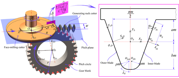
|
| Figure 1. A brief generating mechanism of curvilinear cylindrical gears |
After a series of coordinate transformations generate the virtual face-milling cutter surfaces, the gear tooth surfaces can be generated by the curvilinear gear machining principle. The curvilinear gear machining principle is as follows:
(1) Before processing curvilinear cylindrical gears, the cutter pitch plane always remains tangent to the pitch circle of the gear blank. Meanwhile, the rotation axis of the face-milling cutter has to retain one translational and one rotational degree of freedom, and the rotation axis of the gear blank only retains one rotational degree of freedom. Here, the direction of the rotation axis of the face-milling cutter is the same as axis , and located at the geometric center of the face-milling cutter, the rotation axis of the gear blank is the same as axis , and located at the geometric center of the gear blank.
(2) In the process of machining the gear, the face-milling cutter continuously rotates around axis with angular velocity , which does not effect on the generated geometry of the gear tooth surfaces. Furthermore, the face-milling cutter reciprocates at lineal velocity along the direction orthogonal to the gear axis . Meanwhile, the gear blank is rotated alternately clockwise and counterclockwise by a specific angle under the angular velocity . Namely, the cutter always does pure rolling relative to the gear blank. Then, the moving velocity of the cutter and the angular velocity of the gear blank must satisfy the following equation:
|
|
(2) |
Here, expresses the pitch radius of the to-be-generated curvilinear cylindrical gear.
(3) When the gear blank moves with the cutter at the same time based on the method in the previous step, the gear tooth surfaces are generated as the envelope to the family of positions of the virtual cutter surfaces. The family of positions of the virtual cutter surfaces can be represented in coordinate system . The coordinate transformation from coordinate system to is represented by the following matrix
|
|
(3) |
After one tooth space is generated by the face-milling cutter, the gear blank is indexed by one tooth pitch angle, and the generating mechanism of the gear continues to generate the next tooth space, until all tooth spaces have been formed.
2.2 Derivation of mathematical model of the wheel tooth surfaces
Figure 1 (Right) shows the straight-line profiles of the face-milling cutter for the generation of the wheel tooth surfaces. The inner and outer blade profiles are divided into two parts: the straight-line profile, which will be used for generation of the working part of the wheel tooth surfaces, and the circular arc profile, which will be used for generation of the fillet part of the wheel tooth surfaces. The variable represents the distance between arbitrary points on the straight-line profile and the origin of coordinate system or , and the variable represents the polar angle of arbitrary points on the circular arc profile.
The working and fillet parts of the wheel tooth surfaces will be derived, respectively.
The position vectors of a point on the straight-line profiles can be expressed in the coordinate systems and , as follows:
|
|
(4) |
The coordinate transformations from and to are represented by the following matrixes:
|
|
(5) |
|
|
(6) |
Then, the inner and outer blade profiles are expressed in coordinate system as
|
|
(7) |
|
|
(8) |
The virtual face-milling cutter surface is represented in coordinate system as
|
|
(9) |
From now on, if both upper and lower signs appear in matrixes. Then, the upper sign represents the inner blade or convex side, while the lower sign represents the outer blade or concave side.
Regarding the fillet parts of the cutter, the position vectors of a point on the circular arc profiles can be expressed in coordinate systems and , as follows:
|
|
(10) |
|
|
(11) |
The coordinate transformations from and to are represented by the following matrixes:
|
|
(12) |
|
|
(13) |
Then, the inner and outer circular arc profiles are expressed in coordinate system as
|
|
(14) |
|
|
(15) |
The virtual fillet parts of the face-milling cutter are represented in coordinate system as
|
|
(16) |
According to the proposed methodology of generation of the gear tooth surfaces in section 2.1, the parametric representations of the family of positions of the cutter surfaces in coordinate system , are given by Eqs. (17) and (18)
|
|
(17) |
|
|
(18) |
According to the theory of gearing in [12], the equations of meshing may be derived as follows:
|
|
(19) |
|
|
(20) |
Therefore, the generated working and fillet surfaces can be obtained as follows:
|
|
(21) |
|
|
(22) |
In Eq. (21), and are the parameters of the working tooth surfaces. In Eq. (22), and are the parameters of the fillet surfaces, and is the generalized parameter of movement. Arbitrary point coordinates on the wheel tooth surfaces will be solved by numerical method.
2.3 Derivation of mathematical model of pinion tooth surfaces
The generation of a mathematical model of the pinion tooth surfaces is similar to that of the wheel tooth surfaces. They distinguish only in different cutter blade profiles. Here, the face-milling cutter with the parabolic blade profiles is used to generate the pinion tooth surfaces. Figure 2 shows the parabolic profiles of the face-milling cutter. The parabolic profiles of the cutter retain tangent to the standard blade with straight-line profiles. The point of tangency is located at arbitrary positions on the straight-line profiles. The distance between the point of tangency and the cutter pitch plane is along the vertical direction. The distance between the center points of circular arc profiles and the origin of the coordinate system is along the horizontal direction. The variable represents the distance between arbitrary points on the parabolic profile and the origin of the coordinate system or . The variable represents the polar angle of arbitrary points on the circular arc profiles.
The working and fillet parts of the pinion tooth surfaces will be derived, respectively.
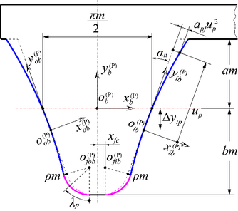
|
| Figure 2. The parabolic profiles of cutter for generation of the pinion tooth surfaces |
The position vectors of a point on the parabolic profiles can be expressed in the coordinate systems and , as follows:
|
|
(23) |
|
|
(24) |
The coordinate transformations from and to are represented by the following matrixes
|
|
(25) |
|
|
(26) |
Then, the inner and outer blade profiles are expressed in the coordinate system as
|
|
(27) |
|
|
(28) |
The virtual cutter surfaces are represented in the coordinate system as
|
|
(29) |
Regarding the fillet parts of the cutter, the position vectors of a point on the circular arc profiles can be expressed in the coordinate systems and , as follows:
|
|
(30) |
|
|
(31) |
The coordinate transformations from and to are represented by the following matrixes
|
|
(32) |
|
|
(33) |
Then, the inner and outer circular arc profiles are expressed in the coordinate system Sb as
|
|
(34) |
|
|
(35) |
The virtual cutter fillet surfaces are represented in the coordinate system as
|
|
(36) |
|
|
(37) |
According to the proposed methodology of generation of the gear tooth surfaces in section 2.1, the parametric representations of the family of positions of the cutter blade surfaces in coordinate system , is given by Eqs. (38) and (39).
|
|
(38) |
|
|
(39) |
The equations of meshing for the pinion tooth surfaces may be derived as follows:
|
|
(40) |
|
|
(41) |
Therefore, the generated working and fillet surfaces can be obtained as follows:
|
|
(42) |
|
|
(43) |
In Eq. (42), and are the parameters of the working tooth surfaces. In Eq. (43), and are the parameters of the fillet surfaces. is the generalized parameter of movement.
Regarding the determination of parameter . Due to the edge radius of the cutter blades and parabola coefficient being constant. When the parabolic profiles tangent to the circular arc profiles, unit normal vectors of the parabolic profiles are equal to unit normal vectors of the circular arc profiles at the point of tangency. Simultaneously, the position vectors of the parabolic profiles are equal to the position vectors of the circular arc profiles at the point of tangency. Therefore, the parameter can be determined by Eq. (44)
|
|
(44) |
where,
|
|
(45) |
|
|
(46) |
In Eq. (44), there are three independent scalar equations with three unknown parameters (, and ). Therefore, the three unknown parameters are easy to solve.
3. Finite element model for stress analysis
In order to create a precise finite element model (FEM), point clouds on the tooth surfaces are employed to generate nodes and hexahedral elements of FEM. Here, the point cloud coordinates come from the tooth surface equations and . This method of establishing nodes and elements of a gear set comes from Litvin et al. [12]. Accurately defining the initial contact position and boundary conditions of the gear set is a key step for establishing a FEM of gear sets.
3.1. Initial contact position of gear sets
The definition of initial contact position is essential for finite element analysis of the gear sets. It takes the position where the gear sets with assembly errors just contact as the solution target. That is, when the tooth surfaces of the gear sets are just in contact, the initial rotation angle of the two matched gears is calculated.
The assumption, the pinion is fixed to coordinate system , and it rotates around the axis of coordinate system which is rigidly fixed to the gear transmission frame. Moreover, the wheel is fixed to the coordinate system which is separated with respect to the coordinate system by a distance along the axis direction. The relative position of the wheel with respect to the pinion has four assembly errors: axial displacement of the wheel with respect to the pinion (), the center distance error (), intersecting shaft angle error (), crossing shaft angle error () (Figure 3).
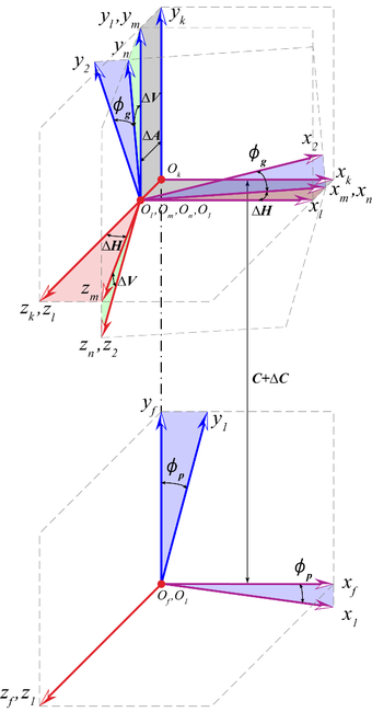
|
| Figure 3. Definition of coordinate systems under gear assembly errors |
To solve the initial contact points on the gear tooth surfaces when the wheel is in meshing with the pinion. Both the wheel and pinion tooth surfaces have to be expressed in the same coordinate system . The pinion tooth surfaces are represented in the coordinate system as follows:
|
|
(47) |
where,
|
|
(48) |
In Eq. (47), the function (, ) represents that the parameter in Eq.(40) is expressed by the parameter and .
Introducing four assembly errors, the wheel tooth surfaces are represented in the coordinate system Sf as follows:
|
|
(49) |
where,
|
|
(50) |
|
|
(51) |
|
|
(52) |
|
|
(53) |
|
|
(54) |
In Eq. (49), the function (, ) represents that the parameter in Eq.(19) is expressed by the parameter and .
When the wheel is in meshing with the pinion, Both the wheel and pinion tooth surfaces must be in continuous tangency, their position vectors and unit normal vectors coincide at arbitrary points of tangency. Thus,
|
|
(55) |
In Eq.(55), there are five independent scalar equations with six unknowns. If the initial rotation angle of the pinion is given, the position of the initial contact point on the gear tooth surfaces, and the initial rotation angle of the wheel will be solved by numerical method. The initial rotation angle (, ) and four assembly errors (, , , ) will be used for the assembly of the gear set in the finite element model.
3.2. Definition of boundary conditions
Finite element method is one of the basic approaches of stress analysis, and it can be used for the simulation of contact and bending stresses of gear drives [24-26]. Boundary conditions are a significant part of FEM. The following is a detailed creation method of FEM of the gear set.
Figure 4 shows the schematic diagram of the three-tooth finite element model for stress analysis. The number of nodes and elements in the three-tooth model is simplified and does not represent the actual number of nodes and elements. Generally, to ensure enough boundary conditions for precise stress analysis, the three-tooth models are employed for finite element analysis of the gear drives. The number of elements of each gear model is 73500 with 88995 nodes. The element type is C3D8I, the hexahedral first-order three-dimensional solid element. The material of the gear set is steel with specific material properties (Table 1). In Figure 4(c), the gear ring surfaces and two gear rim surfaces are rigidly constrained to the reference points on the gear axes. All degrees of freedom of the reference point (RP-1) on the pinion axis are constrained, but the rotation degree of freedom of the reference point (RP-2) on the wheel axis is only released. In addition, a resisting torque is applied to the axis of the wheel. Account of no remarkable advantage has been found when the concave or convex sides of the gear tooth surface as driving surfaces [20]. In this paper, the concave sides of the pinion tooth surfaces are defined as master surfaces (Figure 4(a)), while the convex sides of the wheel tooth surfaces are defined as slave surfaces (Figure 4(b)). When the stress is solved for a contact position, the pinion rotates ( around the axis, and the stress solution is performed for the next con tact position. Until stress analysis of 21 contact positions along a meshing cycles is entirely completed. Finally, collecting the contact and bending stresses at all contact positions.
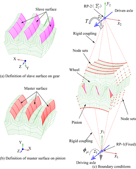
|
| Figure 4. Definition of three-tooth finite element model |
4. Numerical examples
In this paper, four group examples are employed for investigation of contact stresses, bending stresses of the proposed gear drives, and all examples of curvilinear cylindrical gear drives remain free of undercutting and interference. The basic design data of the curvilinear cylindrical gear drives are shown in Table 1 for all examples.
| Parameter | Values |
|---|---|
| Number of teeth, | 31/40 |
| Module, (mm) | 4 |
| Normal pressure angle, (deg) | 20 |
| Addendum coefficient, | 1 |
| Dedendum coefficient, | 1.25 |
| Face width, (mm) | 30 |
| Edge radius coefficient, | 0.38 |
| Young’s Modulus, (MPa) | 210000 |
| Poisson’s ratio, | 0.3 |
| Resisting torque, (Nm) | 400 |
4.1. Example 1
In this group example, four assembly errors are determined as independent experiment variable, respectively. The main purpose is to investigate the influence of assembly errors on contact stresses, bending stresses. Here, the cutter mean pitch radius mm, the parabola coefficient , and the offset distance of parabolic profile mm. The design data of the assembly errors are shown in Table 2. There are four kinds of assembly errors, each assembly error is composed of 4 cases.
| Type of assembly errors | (°) | (°) | (mm) | (mm) | ||||||||||||||||
|---|---|---|---|---|---|---|---|---|---|---|---|---|---|---|---|---|---|---|---|---|
| Error values | 0 | 0.05 | 0.1 | 0.2 | 0 | 0.05 | 0.1 | 0.2 | 0 | 0.1 | 0.2 | 0.5 | 0 | 0.1 | 0.2 | 0.5 | ||||
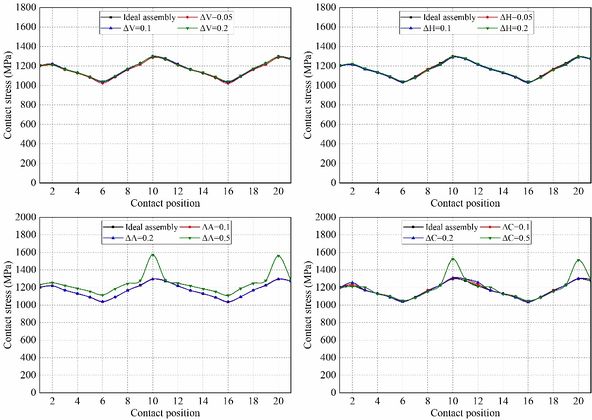
Figure 5 shows the evolution of contact stresses for the gear drives designed for example 1. The intersecting shaft () and crossing shaft angle errors () have no effect on magnitudes of contact stresses, but the contact position is slightly shifted toward the gear edge with increasing assembly error (Figure 6(a) and (b)). The red curves represent the centerline of the gear along the tooth width in Figure 6, and the red curves in stress contours that appear later in this article also represent the centerline of the gear. The axial displacement error () and center distance errors () have no effect on contact stresses unless the values of axial displacement error and center distance error are too large. If and are too large, severe contact stresses appear on the addendum edge of the gear at contact positions 10 and 20. With the gear set rotates, the pinion rotates exactly one cycle from contact position 10 to 20, so the stresses are almost equal at these two contact positions. Among them, the stress contours of contact position 10 is shown in Figure 6(c) and (d). In Figure 6(c), it can be seen that the offset of the contact patterns increases with the increase of the magnitude of . In Figure 6(d), there is no offset of the contact patterns with the increase of the magnitude of .
|
| Figure 5. Evolution of contact stresses for gear drives designed for example 1 |
|
| ||||
| Figure 6. Stress contours at specific contact positions under four assembly errors |
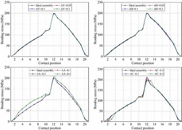
Figure 7 shows the evolution of bending stresses for the gear drives designed for example 1. The intersecting shaft error () and crossing shaft angle error () have no effect on bending stresses. The axial displacement ) error and center distance error () have no effect on bending stress unless the values of axial displacement error are too large. If is too large, the mean bending stresses are increased. To sum up, the suitable assembly error is not sensitive to the contact stress and bending stress of the curvilinear gear sets.
|
| Figure 7. Evolution of bending stresses for gear drives designed for example 1 |
4.2. Example 2
In section 4.1, it has been confirmed that assembly errors benefit the reduction of transmission errors for the gear drives with parabolic profile. In this section, assume that the assembly error of the gear drives is defined as °, the cutter mean pitch radius mm, the offset distance of parabolic profile mm. The parabola coefficient is determined as the independent experiment variable. The design data of parabola coefficients are shown in Table 3.
| Case | 1 | 2 | 3 | 4 |
|---|---|---|---|---|
| Parabola coefficient, (1/mm) | 0 | 0.0005 | 0.001 | 0.0015 |
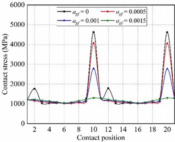
Figure 8 shows the evolution of contact stresses for the gear drives designed for example 2. Maximum contact stresses during the meshing cycle occur at contact positions 10 and 20, and the contact stresses decrease with a higher parabola coefficient at contact positions 10 and 20. It can be seen from Figure 9 that the maximum contact stress at contact position 10 occurs at the tooth tip, which is caused by the insufficient modification of the tooth tip. Therefore, the parabolic modification can eliminate the edge contact at the addendum.
|
| Figure 8. Evolution of contact stresses for gear drives designed for example 2 |

|
| Figure 9. Stress contours at contact position 10 for example 2 |
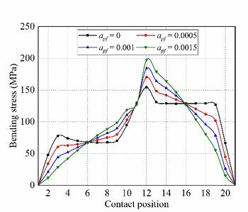
Figure 10 shows the evolution of bending stresses for the gear drives designed for example 2. In the meshing cycle, the maximum bending stress magnitude increases with the parabola coefficient increment. In the first half cycle (Contact position 1-11), with the increase of the parabolic coefficient, the bending stress first decreases and then increases; in the second half cycle (Contact position 11-21), it is just the opposite.
|
| Figure 10. Evolution of bending stresses for gear drives designed for example 2 |
4.3. Example 3
In this group example, the cutter mean pitch radius is determined as the independent experiment variable. The axial displacement error mm, the parabola coefficient 1/mm, and the offset distance of parabolic profile mm. The design data of the cutter mean pitch radius are shown in Table 4.
| Case | 1 | 2 | 3 | 4 |
|---|---|---|---|---|
| Mean radius of cutter, (mm) | 40 | 60 | 80 | 100 |
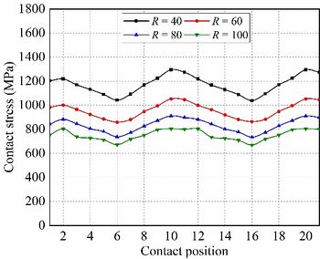
Figure 11 shows the evolution of contact stresses for the gear drives designed for example 3. In the meshing cycle, the maximum contact stresses at any contact position are reduced with the increment of the cutter mean pitch radius. It can be seen from Figure 12 that as the cutter radius increases, the width of the contact pattern also increases, at the same time, the increase in the width of the contact pattern leads to a decrease in the contact stress. However, the center point of the contact pattern is more seriously offset under the same assembly error.
|
| Figure 11. Evolution of contact stresses for gear drives designed for example 3 |
| Figure 12. Stress contours at contact position 10 for example 3 |
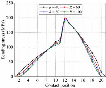
Figure 13 shows the evolution of bending stresses for the gear drives designed for example 3. In the meshing cycle, maximum bending stresses are less affected by the cutter mean pitch radius. To sum up the above, the results show that a higher cutter mean pitch radius can improve the meshing characteristics of the gear drives.
|
| Figure 13. Evolution of bending stresses for gear drives designed for example 3 |
4.4. Example 4
In this group example, the offset distance of the parabolic profiles is determined as the independent experiment variable under ideal assembly conditions. The cutter mean pitch radius mm, and the parabola coefficient /mm. The design data of the offset distance of the parabolic profiles are shown in Table 5.
| Case | 1 | 2 | 3 | 4 | 5 |
|---|---|---|---|---|---|
| Offset distance of parabolic profile, (mm) | 0 | -1 | -2 | -3 | -4 |
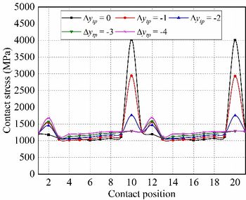
Figure 14 shows the evolution of contact stresses for the gear drives for example 4. In the meshing cycle, the maximum contact stress occurs at contact position 10 and 20, it reduces with higher the offset distance towards tooth root at these contact position. The contact stresses increase with higher the offset distance except contact position 10 and 20. It can be seen from Figure 15 that the reason for the reduction of the contact stress at the contact position 10 is that the addendum edge contact is gradually eliminated in the process of increasing the offset amount. Therefore, an appropriate offset amount can reduce the maximum contact stress during the meshing cycle.
|
| Figure 14. Evolution of contact stresses for gear drives designed for example 4 |

|
| Figure 15. Stress contours at contact position 10 for example 4 |
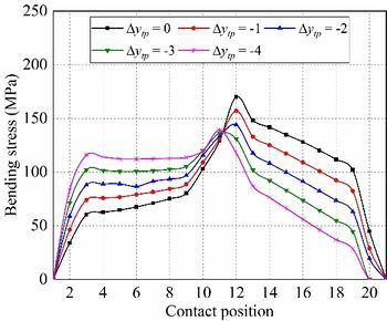
Figure 16 shows the evolution of bending stresses for the gear drives designed for example 4. In the meshing cycle, maximum bending stresses are reduced with the increment of the offset distance of the parabolic profile. Bending stresses are increased with the increment of the offset distance during the first half cycle (Contact position 1-11). In addition, bending stresses are reduced with the increment of the offset distance during the second half cycle (Contact position 11-21). To sum up the above, the obtained results show higher offset distance toward the tooth root will bring about worse mechanical behavior, higher vibration, and noise for the gear drives without edge contact.
|
| Figure 16. Evolution of bending stresses for gear drives designed for example 4 |
5. Conclusions
Contact and bending stresses of the curvilinear cylindrical gear drives are investigated by four groups of examples, respectively. Based on the research work, the following conclusions can be drawn:
(1) The assembly error is not sensitive to contact stress and bending stress of gear drives. The curvilinear cylindrical gear drives are more suitable for industrial applications with assembly errors.
(2) Tooth flank modification can eliminate tooth tip-edge contact, but it will increase bending stress at the tooth root.
(3) The offset of the modified parabola can also eliminate the tip-edge contact, which reduces the bending stress at the tooth root.
(4) If the cutter pitch mean radius is increased, then the width of the contact pattern is increased, and contact stresses on gear tooth surfaces is decreased. Therefore, a higher cutter mean pitch radius can improve the mechanical performances of the curvilinear cylindrical gear drives.
Acknowledgements
The authors express their deep gratitude to the financial support of Sichuan Provincial Key Lab of Process Equipment and Control (No. GK202211, No. GK201907), Science & Technology Plan Project of Panzhihua City (No. 2021ZD-G-1), Panzhihua Key Laboratory of Advanced Manufacturing Technology (No. 2022XJZD05), Sichuan Vanadium and Titanium Materials Engineering Technology Research Center (No. 2021-FTGC-Z-06).
Conflicts of interests
The authors declared that they have no conflicts of interest to this work.
Nomenclature
| Cutter mean pitch radius | |
| Addendum coefficient | |
| Dedendum coefficient | |
| Face width of gear | |
| Number of teeth | |
| Module | |
| Edge radius coefficient | |
| Pitch radius of the gear | |
| Normal pressure angle | |
| Coordinate system with three mutual perpendicular axes , and | |
| Homogeneous matrix of coordinate transformation from to | |
| Position vector of gear tooth surface | |
| Unit normal vector of gear tooth surface | |
| Generalized parameter of motion during generating process of gear | |
| Center distance | |
| Center distance error | |
| Axial displacement error | |
| Crossing shaft angle error | |
| Intersecting shaft angle error | |
| Parabola coefficient | |
| Offset distance of the parabolic profile |
Superscripts:
Pinion and wheel of gear set
Subscripts:
, Convex side of the pinion and wheel
, Concave side of the pinion and wheel
References
[1] Yang H.-C., Tsai P.-Y. Mathematical model of S-shaped gear surface. Journal of Mechanical Science and Technology, 35(7):2841-2850, 2021. doi: 10.1007/s12206-021-0607-z
[2] Arafa H.A. C-Gears: Geometry and machining. Proceedings of the Institution of Mechanical Engineers, Part C: Journal of Mechanical Engineering Science, 219(7):709-726, 2016. doi: 10.1243/095440605x31481
[3] Liu S.-T. Curvilinear cylindrical gears. Gear Technology, 5(3):8-12, 1988.
[4] Arafa H.A., Bedewy M. C-gears in rotorcraft transmissions: a novel design paradigm. In: International Powered Lift Conference, Philadelphia, PA, USA, October 5-7, pp. 93-100, 2010.
[5] Arafa H.A., Bedewy M. Manufacturability and viability of different C-Gear types: A comparative study. In: ASME (ed) Proceedings of the ASME Design Engineering Technical Conferences, Chicago, IL, USA, August 12-15, pp. 381-391, 2012.
[6] Jia F., Hou L., Wei Y., Li B., You Y. Modelling and bending strength analysis of cylindrical gears with arcuate tooth trace. Australian Journal of Mechanical Engineering, 13(2):77-86, 2015. doi: 10.7158/m13-068.2015.13.2
[7] Tang R., Hou L., Zhou B. Modelling and strength analysis for manufacture-oriented cylindrical gear with arcuate tooth trace. Australian Journal of Mechanical Engineering, 14(2):88-94, 2015. doi:10.1080/14484846.2015.1093217
[8] Zhijun S., Li H., Jinge W., Wei L., Qinglin C. Contact strength analysis of circular-arc-tooth-trace cylindrical gear. Journal of the Brazilian Society of Mechanical Sciences and Engineering, 38(3):999-1005, 2014. doi: 10.1007/s40430-014-0272-6
[9] Zhang X., Xie Y., Tan X. Design, meshing characteristics and stress analysis of cylindrical gears with curvilinear tooth profile. Transactions of FAMENA, 40(4):27-44, 2016.
[10] Qinglin C., Hou L. Parallel translating mechanism process-oriented mathematical model and 3-D model for cylindrical gears with curvilinear shaped teeth. Jordan Journal of Mechanical and Industrial Engineering, 10(3):171-177, 2016.
[11] Zhang Q., Hou L., Tang R., Wen G. Method of processing and an analysis of meshing and contact of circular arc tooth trace cylindrical gears. Transactions of FAMENA, 40(4):11-24, 2016. doi: 10.21278/tof.40402
[12] Yongqiao W., Shuhong Y., Qi Z., Yulin W., Li H. Numerical analysis of isothermal elastohydrodynamic lubrication of cylindrical gears with variable hyperbolic circular arc and tooth trace. Transactions of FAMENA, 42(1):61-72, 2018. doi: 10.21278/tof.42106
[13] Wei Y., Yang Y., Guo R., et al. Integrated wear prediction model for cylindrical gear with variable hyperbolic circular arc tooth trace under mixed elastohydrodynamic lubrication. Journal of Mechanical Science and Technology, 36(8): 4053-4065, 2022. doi: 10.1007/s12206-022-0726-1
[14] Litvin F.L., Fuentes A. Gear geometry and applied theory. Cambridge University Press, Cambridge, pp. 818, 2004. doi: 10.1016/0094-114X(95)90001-4
[15] Tseng R.-T., Tsay C.-B. Mathematical model and undercutting of cylindrical gears with curvilinear shaped teeth. Mechanism and Machine Theory, 36(11):1189-1202, 2001. doi: 10.1016/S0094-114X(01)00049-0
[16] Tseng R.-T., Tsay C.-B. Contact characteristics of cylindrical gears with curvilinear shaped teeth. Mechanism and Machine Theory, 39(9):905-919, 2004. doi: 10.1016/j.mechmachtheory.2004.04.006
[17] Tseng J.-T., Tsay C.-B. Mathematical model and surface deviation of cylindrical gears with curvilinear shaped teeth cut by a hob cutter. Journal of Mechanical Design, 127(5):982-987, 2005. doi: 10.1115/1.1876437
[18] Tseng J.-T., Tsay C.-B. Undercutting and contact characteristics of cylindrical gears with curvilinear shaped teeth generated by hobbing. Journal of Mechanical Design, 128(3): 634-643, 2006. doi: 10.1115/1.2181605
[19] Wu Y.-C., Chen K.-Y., Tsay C.-B., Ariga Y. Contact characteristics of circular-arc curvilinear tooth gear drives. Journal of Mechanical Design, 131(8):081003, 2009. doi: 10.1115/1.3151805
[20] Chen Y.-C., Li Z.-W., Lo C.-C., Wang Z.-G. A study on the improvement of meshing characteristics of a complementary curvilinear gear set generated by complementary rack cutters. Transactions of The Canadian Society for Mechanical Engineering, 41(2):281-291, 2017. doi: 10.1139/tcsme-2017-1019
[21] Chen Y.-C., Lo C.-C. Contact stress and transmission errors under load of a modified curvilinear gear set based on finite element analysis. Proceedings of the Institution of Mechanical Engineers, Part C: Journal of Mechanical Engineering Science, 229(2):191-204, 2014. doi:10.1177/0954406214532907
[22] Fuentes-Aznar A., Ruiz-Orzaez R., Gonzalez-Perez I. Computerized design, simulation of meshing, and finite element analysis of two types of geometry of curvilinear cylindrical gears. Computer Methods in Applied Mechanics and Engineering, 272:321-339 2014. doi:10.1016/j.cma.2013.12.017
[23] Fuentes-Aznar A., Ruiz-Orzaez R., Gonzalez-Perez I. Comparison of spur, helical and curvilinear gear drives by means of stress and tooth contact analyses. Meccanica, 52(7):1721-1738, 2016. doi: 10.1007/s11012-016-0515-y
[24] Wang G., Luo Q., Zou S. Time-varying meshing stiffness calculation of an internal gear pair with small tooth number difference by considering the multi-tooth contact problem. Journal of Mechanical Science and Technology, 35(9):4073-4083, 2021. doi: 10.1007/s12206-021-0819-2
[25] Zhao Z., Yang Y., Ma H., et al. Meshing characteristics of spur gear pairs with tooth modification under different assembly errors and sensitivity analysis for impact factors. Journal of Mechanical Science and Technology, 37(1):149-162, 2023. doi: 10.1007/s12206-022-1215-2
[26] Li D., Liu Y., Gong J., et al. A novel method for longitudinal modification and tooth contact analysis of non-circular cylindrical gears. Journal of Mechanical Science and Technology, 36(12):6157-6170, 2022. doi: 10.1007/s12206-022-1130-6Document information
Published on 18/09/23
Accepted on 30/08/23
Submitted on 11/07/23
Volume 39, Issue 3, 2023
DOI: 10.23967/j.rimni.2023.09.001
Licence: CC BY-NC-SA license
Share this document
Keywords
claim authorship
Are you one of the authors of this document?


